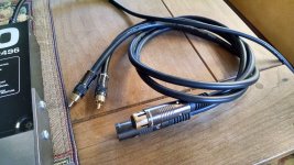
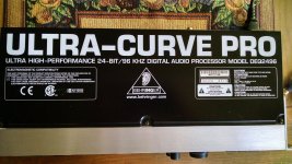
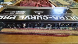
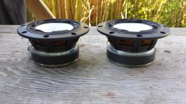
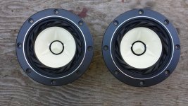
Pair of EAD E60 fullrange drivers successor to Jordan JXR6HD

Hi
This is a mint pair, to be sold boxed in all original packaging and supplied with their measurements from the factory and original invoice. There are no marks, except the solder on the tabs. They have only been lightly used.
I am selling them for half price including shipping within Europe: £100 only for the pair.
michael@arcadianestates.com
Will ship globally for the extra cost.
Payment by paypal only.
Thanks.

SD Card Memory FLAC/WAV 192/24 player - ESS crescendo II - AK4495 - DV20A

Hi all,

Haven't seen this one around on the forum so I thought to give it a shot.
Been on the forum for a couple of years but haven't contributed yet and thought now is a good time 🙂
I've been playing around with a couple of SD card FLAC players for a while now and ran into this one on eBay:

Finished Digital Turntable Lossless Music Player Ape WAV MP3 AK4495 DAC | eBay

Decided to buy it and see how it can be modded to sound any decent.

An externally hosted image should be here but it was not working when we last tested it.


After opening up, the player shows a modular approach. The SD card section is based on the ESS Crescendo II soundbar chip. I spoke with my contacts in ESS to get confirmed that this chip is actually real and capable of doing FLAC decoding on the fly.

An externally hosted image should be here but it was not working when we last tested it.


The ESS chip reads SD cards and USB sticks, clocks the data through it's built in DSP blocks, which at this point should be all 32bit wide audio path.
Apparently this is also where it decodes FLAC up to 24bit 192ksps and does digital volume control.
Via i2s and spdif the resulting digital audio is available.
Seeing the small smd crystal oscillator that clocks the whole thing, I'm thinking there may be something to optimize here.

The second pcb is the i2s AK4495 and power supply board.

An externally hosted image should be here but it was not working when we last tested it.


First thing I had to do was a checkup of the infamous dipswitch that controls the filtersettings of the AK4495 and of course the dipswitch design flaw is present in this board. Removed and replace by 2 jumpers.
Second thing, check the level of pin 5, the SSLOW signal. Luckily this is connected to GND already, so disabled.
The SSLOW signal makes the filters extend their roll off for use at lower than 44.1 kHz sampling frequencies, if I'm interpreting the datasheet correctly, page 28:

http://www.akm.com/akm/en/file/datasheet/AK4495EQ.pdf

The next thing was checking the output circuit. They used a double opamp by JRC, the MUSES8920
I'm not familiar with that chip at all, I'm definitely going to experiment changing it for something else.

The output is connected via 22ohm resistors, thank goodness no crapacitor in the output... BUT because they apparently used 5% resistors or something there was 45mV DC offset in one channel and 16mV in the other. Not so good.
My mod shows a 47K5 fixed resistor / 50K trimpot pair over each DAC output resistor to level away the DC offset. See the image above.

I have to say my first impression, after the mods, is quite positive. I am going to do a lot of listening now and prepare a list of further mods to improve the way the thing sounds.

By the looks of it, there is room for improvement in the decoupling, power supply, clocking and output filter.

Never a dull moment 🙂

I'm curious to know if there's anyone out there that already has done something with a unit like this.

Cheers, Hans.

Symmetrical line preamp

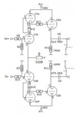
Hi guys, just idea for symmetrical line amp based on famous one which I've found on this forum. May I use is this way please?
Maybe I can do the same with CF at the ouput like with SRPP on input, so use resistor for up and down CF but with 11k value.
Or, do you have any other symmetrical line preamp which you can recommend please?
Thanks.

Attachments

  • idea.jpg
    idea.jpg
    37.7 KB · Views: 452

New MINI ZEN Headphone Amp PCB group order...

zen headamp info,you can download my protel99se ddb file.

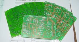
The boards size is 91X64(mm).The price is $4 USD per board.One amp need two piece of PCB. Use CHINA POST(ship) costs is $5 USD.

you need to email me directly to place an order. Instructions on this will be posted to this thread.

Boards, Total = 30 pieces.

My e-mail : zanghb@bjtzh dot gov dot cn

Attachments

  • 87_3.jpg
    87_3.jpg
    42.3 KB · Views: 6,256

LTSpice - comparing 2 simulations

Hey guys, maybe someone knows how to do this.
In LTSpice, is there a way to compare two simulation runs?
For example, say you do a step response and plot the voltage of the node of interest. Then you make a tweak to the circuit and run the simulation again. Now I would like to visually compare the waveform of the previous step response to the current one. Is there a way to do this?
It would be super helpful.

Thanks a bunch!
- Sandro

unsure what speakers

Hi All

For years I have wanted to build speakers but never been able to. Well the time is now. The thing is, I'm not that into high end audio and listed to music on spotify. We listen to a huge range of music, at a large range of volumes and currently have an old logitech 2.1 system. My substantially better half especially, likes a bit of doof doof, so something with good low end or something that has a sub to go with it would be great.

As to why I want to make it, I like to make stuff. I'm a engineer by trade and have access to wood and metal working equipment.

What would you recommend building?

thanks in advance

Denon Tu-500 , No Stereo

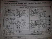
Hi, my frined gave me a TU-500 for no stereo operation. Mono signal work for both channels.
FM stereo light work if i bypass HA1156 mpx chip.
Checked front end with my Leader stereo gen for 100MHZ carrier and 19KHz pilot and L+R audio mod.
Front end and IF if fine as I can tune IF stage to compare once demodulate FM carrier versus the composite output of signal stereo generator to be exact minus some usual distortion of signal,
So the front end is a reply of the composite signal that is a 1KhZ L+R audio with a 19KHz pilot all mix together.
I can with my stereo gen have a 67KHz SCA modulation and I can observe it at the input of the MPX HA1156 chip.
Of course replacing, testing all near components near the HA1156 is been done.
All caps are replaced either the coupling one and filter ones.
Did replaced the HA1156 chip, still no success. No Stereo.

So with signal gen at 100MhZ FM carrier with L+R 1 KHz audio and pilot on
I can follow signals on the HA1156 pins.
All DC voltage looks good with a solid 12 V DC .


I have removed the muting signal and the force mono on pin8 to isolate those.
So the HA1156 have now pin2 input which is composite signal, I did injected a direct composite to the pin2 from my stereo gen no difference, still no stereo indication.
Pin6 remains 6,6vdc.
19KHz signal from this HA1156 is solid compared coming from RF front end or pin10 have same frequency of 19KHz compared with frequency counter and a scope.


Outputs pin 4 and 5 have 10Vdc and L+R 1 KHz audio signals mix with 19KHz, this is before the lowpass filtering on the audio signal.


Filter caps direct on pin 4 and 5 are lifted too, so no interference if they are defective.


So to resume:
VR301 cleaned, C303 checked
C304-305 replaced.
C306 checked
C302 replaced
C301 replaced
R308 lifted
R309 lifted
C307-308 lifted
C311-312 lifted
C329-330 replaced
All close resistors measured OK.


Any other ideas where to look for??
Thanks

Attachments

  • 20200110_135847.jpg
    20200110_135847.jpg
    985 KB · Views: 356

interesting OMNI design...

Stuck in my head, input needed

You might find this post interesting if:
- You like thinking about creative solutions for unconventional problems;
- You like unconventional box designs;
- You like more questions than answers;
- You like my weird thinking;
- You like long posts.

Designing the system of my dreams. I want to walk around the room and not deal with phase cancellation or beaming issues. My ideal speakers sound good at any listening position, can play loud, feel like they're 'breathing', and have an immersive and encompassing quality to them. I have boggled it down to some more concrete requirements. Please bear with me as my convoluted brain processes unfold themselves.

My demands:
- Full range system
- Response 40Hz to 8kHz
- Ability to fill 50m³ room (1766 cubic feet)
- Ability to play loud
- Omnidirectional sound dispersion

Let's break those down!
Full range: Self-explanatory. Definitely no crossover.

Response 40 to 8kHz: Okay, perhaps not full full range... I will be adding in biamped supertweeters (sue me!), but I have all that figured out already. These boxes will be run full range without crossover, and 40-8kHz is what they have to cover. I'm asking your help regarding solely these boxes that will be run full range.

Ability to fill room: 50 cubic meters at least, preferably more. The boxes will have to be able to do this without effort.

Ability to play loud: Sometimes I play metal music loudly and then I don't care much about the audiophile characteristics. Often I will turn down the bass frequencies to take some strain off the drivers. That said, I'm probably wanting drivers with above average Xmax, say 3-5mm (about 1/8th inch - 3/16th inch)

Omnidirectional sound dispersion: Here the interesting part begins!

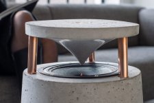
Traditional omnidirectional speaker designs make use of an upward firing driver that shoots audio into a waveguide of sorts, usually a concave cone that reflects audio 360° [attachment 1]. The sound heard would be the sound that is reflected off the waveguide. Unfortunately, this leads to some loss of sensitivity (compared to the point-source measurements supplied by the manufacturer). A driver that is listed as 96dB/m (1W) will most likely measure around 93dB/m when integrated in this traditional omnidirectional box design. (Correct me if I'm wrong.) Loud full range drivers are rare to begin with, so losing sensitivity is tough when my other requirement is for these speakers to play loud.

This introduces some unconventional restrictions on the box design. For the last months, I have been weighing the pros and cons of two options:
- Upward firing driver into a flared conical waveguide [attachment 1]
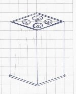
- Multiple smaller drivers shooting upward into the air [attachment 2]

Let's break it down.

Option 1 - Upward firing driver into waveguide: This is the traditional omnidirectional design. I would want a high-sensitivity driver with a stiff cone that can handle about 40 Watts nominal, and has about 3-5mm Xmax. How about that for asking for the impossible…
Though I do think I would have some options here. For example, the Tangband W8-1808 is rated 93dB/m and 30W nominal, while having a stiff bamboo cone and an Xmax of 5mm (about 3/16th inch). Firing this driver upward into a concave cone might still yield ~92dB/m in the upper midrange and about 90dB/m in the lower midrange/upper bass. Combined with a bass reflex, extension to 40Hz could perhaps still be about 89dB/m, which is not unreasonable, if one considers all my demands. (These are educated guesses.) Often I turn down the bass a little bit when I crank up the total volume, so the driver should be able to play anything above 120Hz or so even louder, whilst the decreased bass in the input signal and a not-very-low Qts cause the conus to stay inside the Xmax boundaries. Extending a little outside of the Xmax when cranked is not a problem IMO.
While I think this design would be possible, it does greatly reduce my options regarding driver choice: not many drivers meet the required specifications. I think most drivers that remain are about 8"-10"-12" in diameter and will have to be cone-treated to ameliorate cone breakup issues. Beaming is not much of an issue because of the waveguide.
( In case of the Tangband: 100L ported box (about 3½ cubic feet) tuned to 40Hz. )

Option 2 - Multiple drivers firing upward: Another way to achieve omnidirectional sound dispersion is by having a driver fire upward. The sound you hear then is for the greatest part reflected sound from adjacent walls, and also the ceiling. This design is tried and tested and works great for omnidirectional sound dispersion, but has downsides. Having the driver fire up into the air greatly reduces perceived sensitivity at the point of listening (3dB/m at least, most likely more), since most waves hit the ceiling and the walls before they reach the ear. However, since no waveguide is hanging above the driver, it is possible to multiply the amount of drivers. For example, one could have 4 full range drivers firing upward in order to achieve omnidirectional sound. This would in turn lead to a higher total system sensitivity and a lower required Xmax per driver. Think of it like an upward-firing driver array… that eliminates comb-filtering because of its dispersion pattern. However, since beaming is a thing, smaller drivers would be required in order to achieve pleasant omnidirectional sound dispersion. Luckily, since there are a lot of small-ish full-range drivers (4" or so) out there, a lot more drivers that fit the specs remain as an option.

Other options that I have ruled out:
Angled bipoles: Nope I don't want the large dead spot down the middle
Angled dipoles: Too much drop in efficiency, especially in the bass
OB dipoles out in the room: Don't have enough space in my room to make those truly viable
So, according to my rationale, I'm stuck at a fork in the road, having to choose between the two options listed above. Even though I'm having tunnelvision and I'm missing lots of stuff, I would still like to compare these two options here. I find it hard to imagine whether they would satisfy my demands. I also find it hard to weigh their pros and cons in relation to the ideal that I have in my head.

Therefore I'm curious to your thoughts regarding the two options that I listed.
- Do you think either would satisfy my demands?
- Would you specifically advise against one of the two?
- Do you have experience with either option? Please share.

(Be kind!)

Cheers,
Raoul

Attachments

  • 1.jpg
    1.jpg
    125.7 KB · Views: 579
  • 2.jpg
    2.jpg
    108 KB · Views: 568

Going Bordeaux tops. Couple of questions ...

I really want quality AMTs in my next speakers. So I am purchasing the top portions of the Bordeaux, but making a couple of changes. I need to know if those changes are possible, without redesigning the xover.
I want to use a larger sealed, or ported cabinet, and do away with the dipole set up. While this will not necessitate a change in xover from mid to tweeter, in regards to frequency or slope, BUT will it change the relative volume of the midbass to tweeter transition? Wont it make the woofer now louder, upsetting the balance?
My other question is, other than killing the back wave for a more expansive soundstage, will the xover need any change due to the midbass no longer being opened in the back? The overall tone should not change due to this, should it?
Thank you

Active Volume Control in tube preamp?

I have seen only a few instances of global feedback as the sole method of volume control for a tube amp. Any reason it isn't used more often? What about local feedback?

I know that feedack is used to tune the frequency response in some amp, but care needs to be taken with poles, phase, etc- none of which I could really account for in any of my projects. Anything I did would need to be tuned by ear, which might be OK.

FYI- I have a post about an "ARC" tube preamp if you are interested in where I'm going with this.

Question about 7C tone rotary switches

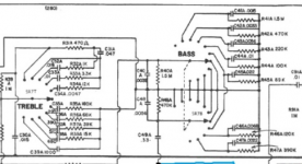
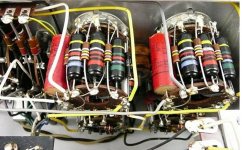
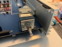
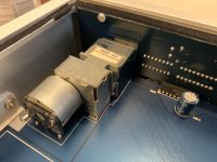
Looking for an answer to something that has puzzled me for a while about the Marantz 7 preamp stepped tone controls. In particular, the schematic shows the bass rotary to be a twin deck switch and treble rotary to be a single deck. Photos of the treble unit shows it has a phenolic disc at its rear connected via standoffs but the disc is used for terminating the other ends of the RC components only and is not a contacts deck.
Photos of the bass rotary switch shows it to also only have a phenolic termination disc at its rear and I'm not seeing a switch deck. All the photos I've seen show a cutout hole at the rear disc of both treble and bass rotary switches.
I would love to hear from someone who can look at these switches and let me know if I'm just not seeing the second switch deck of the bass tone controls or if the actual switches do not match the schematic?

Attachments

  • 7C tonepots.PNG
    7C tonepots.PNG
    92.9 KB · Views: 104
  • 7C bass tonepots.jpg
    7C bass tonepots.jpg
    92.7 KB · Views: 106

6n6p for tremolo

Hey guys!
I have a couple of 6n2p (Russian 12ax7?) and I wanted to add a bias shifting tremolo to a mic preamp based on two 6au6 pentodes that I built out of an old Akai tape recorder.
Im a bit frustrated after hours of messing around with it.. Just cant get that tube to oscillate😕
I tried different feedback caps and resistors for the RC stages, and also experimented with the cathode cap and resistor values and still nothing..
I have 320V for a B+.

Would appreciate any help to get that LFO up and running 🙂

Help with Infinity RS6000

Long story short, one of my friends gave me the old Infinity RS6000 speakers from his dad since he already has a pretty nice setup and I'm the one that's always experimenting with things and building/restoring amps. The RS6000s won't go into my main system, but I still want to get them up and running and try to get the best out of them that I can, within reason of course.


First thing on my list would be to refoam the 2x 10"-woofers and the 1x 2" polydome midrange per speaker and of course get the Emit-K's serviced.
After that I'd replace the electrolytics in the crossover and clean the pots of the speaker controls.
Maybe I'll also add new speaker terminals and also a second set for bi-amping them...
Sounds good so far? Would the RS6000's even be worth the effort?


For all of this and maybe more I would greatly appreciate any info/experience about/with the Infinity RS6000 anyone on diyaudio.com has. Especially how hard (or dangerous, considering many Infinity speakers are amp-killers) they are to drive and how low they dip, how they fit into the Infinity speaker-lineup (I guess somewhere in the middle but surely miles away from the IRS and the Kappa line), what you think about them sound-wise, if they are even worth restoring,...


I couldn't find much info on the web about them, but at least they are listed on infinity-classics with their spec-sheet http://www.infinity-classics.de/technik/manuals/RS_6000_technical_sheet.pdf

Power supply for external boxes

You probably all have this problem. You have a phono preamp, a DAC, a small streamer, or even a turntable with an outboard motor, and they're all powered by one of these wall wartz, and all the manufacturers are doing there darnest to use a different voltage, 12, 15, 18, 20...and often even AC.


So I would like to build a sturdy, low noise power supply, with say 4-5 outputs, each individually switchable between voltage. So I can connect all these boxes to 1 power supply, by making a small adapter cable to convert the socket.


Has something like this been attempted or done ? I'm having some trouble finding the correct search tags to narrow down the results.


Thanks, Pete

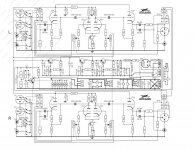
JFET - Mosfet Amplifier inspired by GoldMund Mimesis3

Inspired by the famous GoldMund Mimesis 3, I was intrigued with a naughty idea..
I changed the topology final stage from source follower to common source. With this change, there is a slightly more gain going on this stage and give a more punchy bass. This is according to my personal opinion based on my experience in building solid state power amplifier for more than 20 years, Nevertheless, if this opinion is wrong, please feel free to criticize me 🙂

Minor improvement in the input stage also made, I added variable resistor (trimmer) on the CCS circuit which is, at least on my personal seen, never found in any commercial amplifier. However, being a DIY who has a lot of curiosity and naughty ideas 🙂, I let DIY to spoil their ideas with a trial and error in order to obtain a specific or special character of sound which is most appropriate to personal taste.

With adjustable CCS, we can play with various idle current of differential pairs of 2SK170 (LSK170), from 0.8mA - 3 mA. What is the difference? It is difficult to explain in words, but I just give you a clue : different character of vocal, mid and bass.
Well in the mean time, please enjoy the schematic 🙂
Best regards form Jakarta, Indonesia

Attachments

NAD C521BEE cd drawer problem

Hi all. I'm getting problem with the drawer of my NAD C521BEE player. Instead of the normal just one quick press on the "open" button to open the drawer, occasionally I have to keep on pressing the button for maybe 5 or more seconds before the draw comes out. And at times, have to do this the second time to open it. Moreover, the drawer sometimes closes half-way and comes out again, and has to be closed by pressing the "open" button again. I have replaced the rubber belt and also cleaned with electronic cleaner the "open" button. Also, the socket linking the control PCB to the main PCB circuit board has been cleaned the same way. However, problem still cannot be fixed. Grateful for solutions to the problem. Thanks.

Current measurement in choke input supply

Hi there,

question: In a choke input supply, would it make sense to measure the DC current in the 1st choke and assume that this is the average of the total current in the transformer winding?

As far as I understood the theory, the choke current vs. time should consist of a DC component and a (symmetrically) superimposed AC part...

Background: I almost killed my tube amp by operating it during elevated temperatures last summer. We had 40°C and above outside, and in our flat directly below the roof temperatures reached >30°C. While the transformer was chosen with very narrow margin in terms of power requirements and operating temperature, everything went well until this summer. The 10°C increase in ambient temperature pushed the transformer over the edge, a plastic interlayer insulation started melting and turning brown while releasing an unpleasant odor.

As there is not enough room to throw in a larger EI core, I am going to switch to a toroid. But before ordering the expensive made to order piece, I'd really like to confirm the theoretical current consumption to have enough margin this time.

Regards,
Rundmaus

Velodyne SPL 1000 II distortion

Hello to the group.
I have inherited TWO of these subwoofers that have seen very little use. Unfortunately, they both have severely distorted output. They were driven by a McIntosh MX135 preamp with very long (30 foot) runs of small gauge shielded phono cable thus probably very low input signal strength with a lot of noise. Both failed simultaneously and have exactly the same symptoms. Power on just fine, drivers (subwoofer speakers) are intact, do not rub, and resistance of voice coils are the same. Both were plugged into surge protectors and no known lightning, etc. I have a feeling that the chronic distortion blew something in the sub preamp, but without a schematic to be found anywhere, this amp board is very difficult to troubleshoot. I have a shop complete with all manner of test gear including signal generators, digital Tektronix scope, multimeters, rf voltmeters, etc. I am pretty handy having been a ham for 45 years. One of my hobbies is restoring Collins radio gear. Any suggestions, oh gurus, would be beneficial. If I can fix these things myself, I can avoid about $250 apiece for repairs plus shipping of the amps . I have a feeling that the problem will be identical in both units. Thanks in advance for the assistance.

Rebuilding a 1967 Zenith stereo cabinet. Need some help with Speakers

Hi guys,

I'm working my way through the search results now, but wanted to start a quick thread to see if you could provide some help.

My wife found this cool little cabinet, and we've been interested in building a vinyl hi-fi setup for a while now.

The bad news is that it's mostly stripped, which is kind of good news, because it gives me the freedom to create my own design in a lot of areas.

My plan is to go modern in some areas, like with a U-Turn turntable, but keep some cool vintage touches, like with a Marantz 1030 amplifier.

My question is regarding the speakers. The wiring is stripped, and one of the speakers is trashed, so it looks like I am going to have to rebuild everything. I'd like your input on replacement parts to rebuild the speaker baffles. I can build a new one to fit different components if that's a requirement, i'm fairly handy.

But things like brands, sizes, compatibility and crossovers are currently above my pay grade.

pics:

Cabinet:

dEflbzz.jpg


k1yV0lk.jpg


Gutted insides and speakers:

mptJMKD.jpg


9z1Tx8A.jpg

b500 bass

hi,

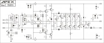
i build a 2 channel b500 from apexaudio but i get small problem. for input i use apexaudio another amplifier input schematic. but there is one thing i see i am losing bass signals in the amplifier or in the input board.

there is schematics. for input it start with 10k resistor and then 100pf capasitor. this can be work like a high filter and cuting my bass signals? and another thing i want to learn. that 2 10k resistors at the -in and + in, if i change them to 1k is it effect to my signal tone? i just want get more volume from amp.

and if some one make b500 amp do i really need a input buffer like that cause b500 have limiter on it. and signal will be coming from mixer. i feeling that input schematic cutting too much signal.

sory for bad english and thank you for al answers.

Attachments

  • APEX BA1000 Input&Display (1).jpg
    APEX BA1000 Input&Display (1).jpg
    115 KB · Views: 155
  • APEX BX500 SCH.jpg
    APEX BX500 SCH.jpg
    449.1 KB · Views: 142

marantz cd6006 power supply issue

Hi all , i'm a bit stuck with a power supply , i have this marantz cd 6006 player i am trying to fix , there seemed to be an issue with the drive motor but i think it was down to the power supply failing , the main transformer is separate , i get 240v at the main transformer plug but it drops to 0 when i plug it in , i thought the transformer could have been shorted but it seems ok .
When i connect the transformer directly to the mains and it works ok without getting hot .
Here are some photos of the psu , i have checked all the caps on the power board , they seem fine . and the 2 transistors on the black heatsinks , they are ok , The third black heatsink is a voltage regulator (7805A) there is no voltage getting to this though ..
If anyone is familiar with this board and could point me in the right direction i would be very grateful .

Dropbox - marantz psu.jpg - Simplify your life


Dropbox - Photo 25-01-2020, 10 10 57 am.jpg - Simplify your life


heres the back of the board

Dropbox - Photo 28-01-2020, 6 49 13 pm.jpg - Simplify your life

  • Locked
China Delays

Do not order anything from China unless you have a month or two to spare. You aren't going to see it anytime soon. I ordered something going on 3 weeks now and it hasn't left China and the T-number from DHL has no record yet.


There are issues with getting the goods to port and also a reduced number of ships for those goods.


Just a heads up, if you are buying anything that has to come from China, you are in for a long wait.

opamp IS, CFP VAS, lateral FET OS

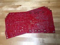
Several moons ago I designed a PCB for one of my experimental amp designs, and at some point braved ordering parts and sending the pcb design off - today the PCB arrived in the post and I've spent a fair few hours putting it together and doing the very first, low power, tests.

The principle is to take advantage of an opamp as both input stage and to close the feedback loop.

The limited voltage output of standard opamps means using a voltage amplification stage to magnify the opamp output somehow, and I've selected a class B CFP stage with gain of about 5, using 4 small-signal transistors.

The output stage is a pair of Exicon lateral MOSFETs, avoiding the issue of thermal compensation for the bias - less complexity with a new design seems a good idea.
opamp_mosfet_amp.png


R6 and R14 form the feedback network for the top CFP pair, setting the gain, and the bias voltage is amplified along with the signal by the CFP sections. The bias arrangement is a bit rough and ready I think, but emulated OK.

The implementation is nearly all surface mount, on a board 3" by 1.5".
opamp_mosfet_amp.jpg

So far I have got the amp basically working, with the minimum of bias needed to prevent instability, about 15mA are taken overall I think. The bias pot I chose was 11-turns which turned out to be a wise choice, but I had to hunt around for a small enough screwdriver to adjust it!

Unloaded it seems to work fine so far (using siggen + 'scope), I need to arrange some form of heatsink before going any further. Its always a relief when a new board basically works without modification.

This design predates my opamp-tripler circuit (see this posting: https://www.diyaudio.com/forums/sol...stacking-voltage-operation-4.html#post5954865)
I will be building that on a PCB that's also just arrived at some point (parts need ordering). It will be interesting to compare the two techniques for leveraging an opamp as integral part of a power amp.

In retrospect I should have use DIP8 for the opamp in this design to allow experimentation with different opamps.


I think the choice of the discrete transistors is fairly non-critical in this arrangement which is a bonus as good audio transistors are getting harder to source. Great opamps at bargain prices are too good a resource to ignore!


[ oh yes, and I know the input network is DC coupled, I think I forgot to fix that ]

Tube Change: Regulator and Rectifier

Hi All

I have a bit of a unique setup and can't find a straight answer for the 300B's I have a preamp that used a 300B for a Rectifier and a 12ax7 & 300B for the regulator portion. I know its basically using a Ferrari engine in a pinto lol

Question, swaping out to lower end 300B's for the rectifier and regulator, will that effect the sound? It came with a pair of factory matched and tested PSVane WE300B replica's. Chaning the 12ax7 to a mullard f91 or others makes a lovely difference in the sound.

Thoughts on swapping out the very expensive 300b's would be nice please

Rockford 2500.1 BD

Good morning Perry,

I dared to open another thread to see if I can finally solve this Rockford or throw it away. The amplifier is in protection, without rectifiers the drive circuit is correct since that verifies it under your instructions and I get a square wave in all the output mosfet, I have rail voltage and the correct voltages in the regulators, as I can do to find out where exactly protection comes from?

FETs switching noise at the output

Hello forum!
I have Jensen 2000.1d D-class amp, which have output switching noise which is present at the output relatively to power source ground:
Blue: VS pin of IR2010S,
(Yellow) (+ terminal).
An externally hosted image should be here but it was not working when we last tested it.


And at the speaker terminals (between speaker ground and + terminal) I'm getting sine wave ~150khz and 4v rms, (it's without any signal at the input).
Is there any way that this could be normal? Amp is working when signal in, though.


I know that some D-class amps self-oscillating, but thing is that before it wasn't any of that noise or sine wave at the output.
Before that all the problem was with blown some of output fets and one gate diode, I've changed them, but After some time turns out that it was also transformers failure, because all irf3205 PSU fets and couple of output 640n's blew up. I've changed them. And now I see this picture.

Amplifier photos jensen amp — Yandex.Disk)

how do you measure acoustic performance of planar?

Hi, I am not experienced with loudspeaker measurement.
I have done some of my boxed speaker following the guide for REW prepared by the author of Vituix cad.
The measurements i took from the Magnepan are full of peaks and null for relatively close measurements. I used gating, and i think i did it right.


The only measurement that seems to make sense is from 8 feets, non gated.
But I know this includes too much of the room, non-quasi-anecoic.


How do you measure, and what are you looking for in the measurement?


Regards,

Hi all, any tips?

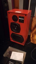
Recently I've been lucky enough to stumble across some Kef Reference 104ab's, recently restored and painted in a very striking orange! Weird color choice, I know, the picture included can't do justice to them. Lovely orange at night, almost red in ambient daylight. I am currently driving them with a Simaudio Moon Ace, which is a 3500 dollar amp. I'm a high school student with a tight budget in need of a good amplifier, with a per channel minimum output of 20 watts. What would be a good combination for my Kef speakers? (budget max of around 200 to 300 dollars)

Personally I have been looking at the Duson PA75 Amplifier, which is to my specification, but I have a very limited knowledge regarding older amps.

Recommendations as to where to start a thread with a question like this would be great!
IMG-20200228-WA0023.jpeg
Happy listening and have a great day!🙄

PCBs, kits, transformers and film caps

Help me with my New Year’s resolution: finish one-project-at-a-time. Instead of buying everything I needed to finish a project, my bad habit of collecting exciting, new parts, passives and PCB’s as they appeared has left me with a cabinet of kits missing critical components. I want to sell the unused hoard to finance the missing pieces.

The prices listed are what I paid, less, or my best guess. All are unused/unsoldered and untested. Since I want to make fewer trips to the post office, a discount for multiple items or reasonable offers for bundles accepted. USPS shipping and hence the continental US strongly preferred; shipping will be calculated per order. I can send/post pictures as needed.


PCBs
1 Diyaudio F4 pcb, $12 for a stereo set
1 Pass Labs B1 stereo PCB, $14


Transformers
1 Antek AS-1212, 100VA, 12V output. $12
5 x Avel Lindberg 40/3010 47/400Hz potted transformers, 115V input, dual 9V@2A output. NOTE: THESE ARE 400Hz TRANSFORMERS. You cannot plug them into a standard 50/60Hz wall supply. Free if you pay shipping.
See pictures at Power transformers, Plitron and other)

Caps (take them all for $50)
1 Hovland MusiCap, 1.0 microFarad, 200V, $3.00
2 Solen MKP-FC, 1.2 microFarad, 400V, $1/ea
2 Kimber KAP, 0.1 microFarad, 600V, $6.00/ea
4 Kimber KAP, 0.022 microFarad, 600V, $6.00/ea
2 MultiCap, 0.10 microFarad, 400V, $12 for a matched pair
4 Rel-Cap, RT series, 0.022 microFarad, 600V, $6 for a matched pair
4 Wima MKP 10, 0.22 microFarad, 630V, $1.00/ea
2 Vishay/Sprague Orange drop, 0.68 microFarad, 100V, $0.75/ea
2 Vishay/Sprague Orange drop, 0.22 microFarad, 100V, $0.75/ea
2 Vishay/Sprague Orange drop, 0.22 microFarad, 200V, $0.75/ea
2 Vishay/Sprague Orange drop, 0.1 microFarad, 600V, $0.75/ea
4 Vishay/Sprague Orange drop, 0.47 microFarad, 200V, $0.75/ea
2 Vishay/Sprague Orange drop, 0.1 microFarad, 400V, $0.75/ea


Other
1 IcePower 50ASX2, 50W Class D stereo amp, non-bridgeable version, with wiring harness, $65


FREE if you order other stuff
2 Raspberry pi rev B 2011.12, $9/ea or free
5 x Avel Lindberg 40/3010 47/400Hz potted transformers, 115V input, dual 9V@2A output. NOTE: THESE ARE 400Hz TRANSFORMERS. You cannot plug them into a standard 50/60Hz wall supply. Free if you pay shipping.


SOLD
SOLD -- 1 sets Diyaudio F4 pcb
SOLD -- 2 sets Peter Daniels F4 pcb
SOLD -- 1 Modified Linkwitz Crossfeed pcb (stereo, headphone use)
SOLD -- 2 Peter Daniels/Brian GT Mini Aleph pcb
SOLD -- Diyaudio Mezmerize older version), stereo pcb
SOLD -- 1 Zen v9 kit with Peter Daniels Zen v9 pcbs, 2 mono boards, 2 power supply boards, and a matched quad of LU1014D
SOLD -- 2 F5 kits, Peter Daniels stereo board, Mofsets - IRFP240/9240; Jfets - Linear J74/K170; Zeners - ZTX 450/550) from Hannes
SOLD -- 2 Diyaudio BA Gain Stage kits, stereo board, 2 matched pairs 2sj313/2sk2013 from Buzzforb
SOLD -- 1 matched quad Toshiba 2SK369GR, IDSS 8mA (grade B), from Hannes
SOLD -- 8 Vishay/Sprague Orange drop, 0.22 microFarad, 400V
SOLD -- 1 Plitron 077017000 2107 standard transformer, 300VA, dual 115V input, dual 30V secondaries
full range line source - help needed!

hi all,

i am considering a full range line source. i'm wanting something that can be eq'd as low as possible. (or perhaps they can go as low as 20hz w/o eq? i'm a novice at this, i dunno). ported or sealed is fine.

anyway, here are the driver specs; i would be using 15 of them.
• VCdia: 11/16"
• Le: 0.42 mH
• Impedance: 4 ohms
• Re: 3.52 ohms
• Frequency response: 45-18,000 Hz
• Fs: 45 Hz
• SPL: 91.3 dB 1W/1m
• Vas: 1.1 cu. ft.
• Qms: 4.25
• Qes: 0.36
• Qts: 0.34
• Xmax: 2 mm
• Dimensions: Overall diameter: 5-1/16"
i'd most likely wire 5 in series; three sets then paralleled for 6.6 ohms total. so, my question is what's cu-ft of the box (or sonotube) that i need to build?

tia,

doug s.

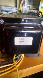
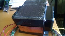
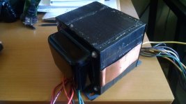
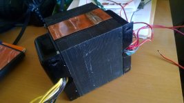
One Electron BFT-1B power transformer

$160 shipped to USA addresses..great shape...no issues


Specifications


Primary: 100, 110, 120, 220, 230, 240 volts at 50 to 60Hz

Secondary #1: 770 VCT @ 360 mA with a set of taps at 520 VCT, capacitor-input filter load

Secondary #2: 5.0 VCT @ 4 A, resistive load

Secondary #3: 6.3 VCT @ 9.6 A, resistive load

Secondary #4: 6.3 V @ 4 A, resistive loadSize: 3.75" x 4.5" x 6" (95 x 114 x 152 m


https://www.tubesandmore.com/sites/default/files/associated_files/p-tbft-1b.pdf

Attachments

  • BFT-1B.jpg
    BFT-1B.jpg
    566.9 KB · Views: 269
  • BFT-1B 2.jpg
    BFT-1B 2.jpg
    487.1 KB · Views: 266
  • BFT-1B 3.jpg
    BFT-1B 3.jpg
    463.7 KB · Views: 256
  • BFT-1B 4.jpg
    BFT-1B 4.jpg
    473.4 KB · Views: 258

Transformer testing: Personal Journey

Recently I have asked questions about AC coupled OPT for valve circuits, and well...let's be honest...I got a little frustrated by the seemingly rule-less selection of OPTs by impedance ratio, and then flamed slightly for quoting my transformer impedance as being the same as the impedance ratio...

So to educate myself, and hopefully show myself that I am not as dumb as some of the more simple comments would imply, I am investigating a number of transformers for suitability in my headphone amp circuit.

Now I have stated that I believe my valve circuit likes a reflected load impedance of 15k to shine, and deliver good THD results (<1%) @ 1kHz.

This was based on the calculated Impedance Ratio of a RS 30VA toroid (196-505):

N = 6.7
N^2 = 45
45*330R = about 15k with 330R headphones.

Q1: But what relevance is the Impedance Ratio?
It defines the output voltage, hence power output

Q2: Does measured Impedance Bandwidth stand close to impedance Ratio?
I am testing this

Q3: Which parameter is relevant here? Z ratio or Z BW? Both?
I hope to find out

Mounting ICEpower 500asp in chassis

Hi,

I am assembling my first stereo ICEpower 500ASP class D amp, and I would like to check if there is a problem in mounting as shown in the picture, without standoffs.

My idea is to add some thermal paste between the amp's heatsing and the chassis base, which is stainless steel so not the best thermal performance, but still better than nothing.

Looking forward to your reply.

Thanks!

Attachments

  • IMG_20200229_121535.jpg
    IMG_20200229_121535.jpg
    440.2 KB · Views: 248
  • IMG_20200229_121524.jpg
    IMG_20200229_121524.jpg
    965.2 KB · Views: 257
  • IMG_20200229_121514.jpg
    IMG_20200229_121514.jpg
    593.1 KB · Views: 265

Rotel ra-940bx tone switch

Hello,
I have a Rotel ra-940bx whose left channel works intermittently. I noticed that the tone switcher might be the cause of the dysfunction as if I play with it the sound sometimes comes back.

Following the suggestion of an amplifier repairman, I tried to spray some wd-40 lubricant and it worked for a while but now the problem is back.


This amplifier is not particularly valuable, but I am kind of fond of it. I would like to try replacing the switcher, to see if it fixes the problem.


I am in no way an expert and I am a bit clueless on where I can find the parts. I searched a bit on the internet but the shops I found did not have the specific part (I would have been surprised otherwise, to be fair).

I would be grateful if you know any shop that might have these type of things or if you could point me in the right direction for a more successful search.
Thank you


Duccio

Hello everyone, a beginner question.

Hello everyone. I'm an ee student from Turkey. I've a bit of experience in digital electronics. Made some simple analog circuits as well. Electronics have always been my hobby and searching on google about my last project led me here🙂


I'm looking for an amp to drive a 20" 4ohm 150w max cont subwoofer in a car. But i got confused after research. TDA1560 seems like an easy way to drive it but i'm not sure if it will suffice in terms of power. My goal is to drive it around 100w to stay away from limits while getting best sound out of it possible. I understand i need to boost voltage level to achive that power, which led me to boostor on this forum.


What amp circuit do you think would be appropriate for this project to use with boostor? Simpler the better. Also what kind of input filter would i need to protect it from cars noise? And one last thing, do you think it would worth to build this sort of system as compared to simple TDA in terms of better bass response? Thanks for reading🙂

lucky goodwill find... vintage Vitavox DU120

A friend of mine bought some end tables for his new appartment at 5$ each.

inside were these 2 near mint Vitavox DU 120. Made in england and apparently still in production. (We can get some vitavox units here in canada for roughly 6k a peice.)


Was wondering if anybody has any comments/ideas on what I should do with these.

I was thinking of making some sealed old style boxes to go with my 60's turntable and 20watt chip amp and hopefully replacing the cap on the tweeter somehow. (although I haven't looked into if that's possible or not)

But really I don't know. These look amazing and should be treated with respect in my opinion.


Regards.

QKdX5Ia.jpg
[/IMG]

bxBVq4L.jpg
[/IMG]

F7DzPvP.jpg
[/IMG]

MomNRlD.jpg
[/IMG]

Horns and Compression Drivers - Screw thread too tight

Greetings.

A while ago I bought some horn flares with 1 3/8 inch screw threads. They were cheap and I thought they might come in handy.

Today I bought some cheap piezo drivers (3 different kinds to play with) planning to screw them into the flares and take some measurements to see if they were any good. Party speakers maybe.

Well, the threads are so tight that I could only screw the first one in about half way. The effort required to UNscrew it was so great the body of the piezo driver broke off in my hand. One driver down and a horn flare with half a tweeter jammed permanently into it. Boo.

So I tried a different driver, very carefully, in another horn. Same deal. So I carefully unscrewed it, applied some vaseline and tried again. Went in easily, about half way, then stopped. Very carefully unscrewed it again, with much effort.

I have now tried half a dozen driver / flare combinations, all the same.

There are no obvious defects in the threads of the drivers or the flares.

Can an experienced soul tell me if this is par for the course (plastic driver thread into plastic horn thread) and if so, what's the trick to getting them in and out.

If this is unusual, perhaps someone might suggest a fix.
Perhaps I just bought dud flares, which is pretty sad because I have dozens of them.

Any advice gratefully received.

Thanks,
blakk

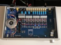
NAD S100 preamp restoring/upgrading

Have a NAD s100 preamp that i like a lot but after 20yrs of use it needs some service.

Have replaced some aging Elna caps (down to half value..) also have some problems with the potentiometer and thinking just replacing it with a new one but hard to source (Alps 20x2 rk27 with motor) I can only find 10, 50 and 100k replacements.
I wonder what would happen if i replaced it with a 10K version? Or a 50K?

Input imp unbal. is 75ohm and balanced 100ohm according to another thread.


Another questions is about the psu and diodes, original it has the IN4003 and i happen to have some BYV26C old stock from Philips(vishay) https://www.vishay.com/docs/86040/byv26.pdf

laying around and what i can see it seems like a good replacement and maybe even some improvements? And something i haven't seen before it's the 2x ceramic caps they've placed before the diodes? Can i replace those with polyester caps i have. Bad feeling seeing ceramics that's all...

Servicemanual: Login - HiFi Engine

Attachments

  • IMG_8627.jpg
    IMG_8627.jpg
    550.3 KB · Views: 623
  • IMG_8592.jpg
    IMG_8592.jpg
    980.5 KB · Views: 556
  • 20190908_115620737_iOS.png
    20190908_115620737_iOS.png
    834.3 KB · Views: 635
  • IMG_8662.jpg
    IMG_8662.jpg
    1,021.7 KB · Views: 1,174

Roland JC-120

I have a Roland JC-120 (serial# 728284) that Has a relatively loud 60Hz buzz through the speakers. Also, no audio. None of the fuses are blown. I need the correct repair manual for that version. Also if anyone has any suggestions on what may be wrong, I'd really appreciate it. I'm thinking rectifier diodes or filter caps. The bridge rectifiers in this version are individual diodes as opposed to a single bridge rectifier brick.

Thanks,
Ron

* edit: Bridge rectifier diodes and Filter caps all test okay.

Anyone familiar with NS10 tweeters disassembly?

I wonder if anyone ever disassembled Yamaha NS10 tweeter for dome replacement etc. My dome seems to have come unglued partially on one side. When I run frequency sweep it buzzes at certain frequency but when I push lightly on the dome side edge it goes away.
I've started to open it up, took out the three screws but it wasn't coming apart so I've stopped because I have no idea if the front plate is also glued together, thus me forcing it apart could rip out the coil and who know what else is in there.
Any advice would be appreciated, thanks.

Headphone tube amp components upgrade

Hello folks!

Im doing some experiments on tube circuits. I have this schiit audio valhalla fully tube headphone amp. I would like to know which kind of upgrade or customization i can make on this. Is it possible to get a cleaner sound or refined sound changing, for exemple, the capacitors for better quality ones? Or maybe the transformadores?

I would like to get the best out this circuit, any tips for upgrade?

Thanks!

open1.jpg

Electromcompaniet AW100 Component Identification

A few years ago, my AW-100 developed an intermittent crackle in one channel that was annoying enough to be noticed, but infrequent enough to be really difficult to diagnose. I did the dry joint and freezing spray check. No luck.

I sent it to a technician who tried to get the service manual and lo and behold, EC stuck their Serial Numbers onto the amps with a paper sticker which has been lost to antiquity. The technician sent it back to me, and I have not had luck finding a matching schematic so far. I think this is a really early AW-100, based on the lack of PCB markings and the dried flux residue everywhere.

I was told to try replacing all the output stage Electrolytic Caps, which seem like low hanging fruit. But then I saw these mysterious components labelled: "1000 H" and "470 H". Does anyone know what are they, and if so are they worth restuffing?

Attachments

  • IMG-3654.jpg
    IMG-3654.jpg
    993.3 KB · Views: 103

1 buffer for 2 channels or not

Hello.
I need to buffer 1 signal to 2 channels.
I need help to determine if I can use a single buffer opamp to send the buffered signal to 2 different channels ?
What is the optimal setup for lower noise ?
Thank you.
An externally hosted image should be here but it was not working when we last tested it.

EDIT: I will not use the lt1018 it just for illustration purpose.

Fmu22u replacement in Skar RP-4500

I have a Skar RP-4500.1 with blown Power section which uses IRF3205PBF and dual series rectifier FMU22U.
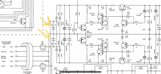
The FMU22U's were blown to shreds. I was hoping ether of the attached datasheet would be a suitable replacement. I don't mind the package style because the heatsink will have kapton tape as an insulator.

Attachments

Phantom Center Speaker w/L-pad & bass blocker

I am looking to add a center speaker to my car audio system. After all I've read I think the Left + Right will be the best way to go for this build. I want to include a L-PAD and a capacitor to lower the volume and to block low frequency because it will be a small 3.5in speaker. How should I wire this??? My thought is that the L-pad would be in line with the positive speaker wire with terminal one grounded to the chassis, terminal 2 from the left positive speaker lead, and terminal 3 to the positive of the speaker. I think the negative of the speaker would go directly to the right negative lead. Does this sound correct? Where do you think the bass blocker should be placed? Before or after the l-pad? Any other suggestions would be greatly appreciated and I would love to start a conversation about different options. Thanks!!

Subwoofer TL in a sphere?

I have a 22" fiberglass sphere that I would like to use as an enclosure for either a sub or a bass driver BUT as a transmission line. I have been trying to imagine the (internal) design problems that would come with this project. Since I have never built a TL but only modified a pre-exisiting one, I am having difficulties with the design of the internal chambers. Most TL cad programs are for boxes (of sorts) with at least 2 parallel walls.
Does anyone have any experience building a TL in a sphere? Any help would be appreciated.
Thanks in advance.

Seas U22REX/P-SL any good in a ported 2way

Hi all,


I'm retrofitting/upgrading/rebuilding some speakers into existing 36L ported cabinets. I have a preference for rigid cones with proper pistonic motion and avoiding crossovers in the 300Hz-3kHz region. Rigid (metal) cones won't allow for this in an 8" woofer and I am limited to 8" woofers by the existing cabinet. I had pretty much concluded the only way to get what i want is to go 3 way, but this does complicate design and crossover significantly. (will be driven by 2 way active crossed amp, so i would have to passively cross the mid/tweeter if i went 3 way)


Then i found the Seas U22REX/P-SL, which professes super duper frequency response all the way to 4kHz, while (presumably) retaining a nice stiff woven cone. problem is is was custom designed by seas to be a lower mid in an open baffle Linkwitz design, very different to what i'm proposing and i'm wondering if it would even be suitable in a ported 2 way.


Does anyone have experience with this driver?

suggestions welcome 🙂

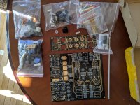
Thoughts on this "ARC" preamp circuit

I bought the following. If there is any interest, I will post my project ideas. I started a lengthy description of my needs and design goals. It seemed a bit much for an introduction. I'll post that tomorrow.

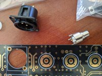
First- most of this project is unnecessary. It is for fun, although I do need the switching capabilities of a preamp without the gain. My amp is a Volksamp Aleph 60, 60-100 watt clone with a sensitivity of 1.25 v to reach full output depending on the speaker load. Everything I have puts out more than 2v. It has a 52k input impedance with the balanced inputs.

Second- I have no issues using a "clone" like this without consent from the manufacturer as there is nothing here that hasn't already come in circuits designed 80 years ago. You shouldn't be able to patent physics (yeah, I'm looking at you, Bose). I'm also not convinced it is actually a clone of anything.

Third- I'm posting because the actual components in the kit look decent and I'm pretty impressed with the quality of the whole thing for the $125 I paid for it.

I'm willing to entertain heavy changes but have no issue with the cathode follower as an output topology. Although that cathode resistance of the 3 parallel resistors seems super low, but more on that later.

Active volume control using feeback?


Thanks.

Attachments

  • AudioResearch-ARC-Tube-Preamplifier-XLR-RCA-In-Out-12AU-ECC82-6DJ8-ECC88-_57.jpg
    AudioResearch-ARC-Tube-Preamplifier-XLR-RCA-In-Out-12AU-ECC82-6DJ8-ECC88-_57.jpg
    223.1 KB · Views: 226
  • jacks.jpg
    jacks.jpg
    978.6 KB · Views: 161
  • kit.jpg
    kit.jpg
    1,005.5 KB · Views: 166
  • pcb.jpg
    pcb.jpg
    1 MB · Views: 228
  • vol pot.jpg
    vol pot.jpg
    771.7 KB · Views: 150

Phenolic Resin (Lab Top) Audio Rack Shelves

I once made an audio rack out of salvaged maple butcher block for shelves and small aluminum I-beams vertical posts. Problem is the old maple started to split because of past improper storage.

I need to rebuild the rack with new wood or use a different material.

I was thinking of trying phenolic resin or epoxy resin shelves/tops, the same thing used in lab tables and countertops.

I might be able to source some used from the local university property disposition warehouse that is open to the public on the cheap, but would have to cut it down.

Question is, would this be a good material to use?

Uncutable safely?

Too weak to hold a lag bolt which is how my old rack was held together?

It will not sound good as it will suck too much energy out?

I see that a few high-end racks use it as trimming or some special composite mix of their own that seems to be similar.

I've also read that some high-end loudspeaker makers use it in their enclosures for it's anti-resonance qualities.

I do not see anyone doing exactly what I have in mind, just beating the bush to see what flies out.

Top 5 Materials To Consider For Your Lab Countertops

Are there any HPL (High Pressure Laminate ) audio rack shelves in use?

WTB Thiel SCS tweeter

Hi everyone 🙂

I have a pair of Thiel SCS monitors that I just picked up that need replacement tweeters

The SCS uses a coax driver from Seas (the 17RE series, 170mm , 2 way )

The tweeter uses a 26mm fabric dome, with neo magnet that fits in the voice coil opening- the woofer cone acts as a horn for the tweeter

The tweeters are easy to remove with only a slight push from behind

*See attachment for driver/ tweeter specs

The old tweeters work but have very low output. I do not know if they have been over-driven or if the ferrofluid has become gelled.

* Not a crossover issue

Anyone have a pair of tweeters?

Much thx

SW

Attachments

Hartke BA900 Bass Amp Combo - Transformer Needed

Hello there,

1st post here for me and hoping someone might be able to help - I have a Hartke BA900 bass combo amp. Great little unit, has done me good service for years since I bought it s/h, but died yesterday - no sign of life.

Had it to bits to find both inline T1.6A fuses blown, so got some new ones. Blew the new ones straight away. Diagnosing the fault seems to point to the (pretty big and possibly torrodial) transformer being the issue - when I disconnect the xformer o/p from the PCB (i.e. just the AC jack, power switch and xformer in the picture) it still blows the fuses so dont think its the amp board.

Disconnecting the orange wire which runs to the xformer input stops the fuses blowing, switch neon stays on but no amp noise or action at all. So I think the winding is probably shorting.

I cant find *any* trace of Hartke online - old post pointed to Korg, who told me helpfully today that its Hal Leonard Pro Audio who support these... HL dont have a service dept to phone, just proaudio@halleonard email - tried them and got a bounce back from their server - duff address :-(

Anyone got any idea where to get a replacement xformer at all? Seems a real shame to scrap the amp for a 10 min swap out job.

Many thanks for any help you can give,

Cheers
David
Projects by fanatics, for fanatics
Get answers and advice for everyone wanting to learn the art of audio.
Join the Community
507,633
Members
7,881,099
Messages

Filter

Forum Statistics

Threads
405,906
Messages
7,881,099
Members
507,633
Latest member
depsc