Purifi 1ET400A Input buffer

I'm thinking about building some slim monoblocs with the Purifi 1ET400A.
When I look online for buffers, it seems that there are only buffers where the Hypex 1200A400 is to be used. However, to me it seems like overkill to use this when it is to be used as mono. In addition, it is a bit larger 🙁

Is it true that you cannot buy or build yourself a buffer where the smaller SMPS600N400 is to be used?

Can anyone help with some links if available?

lubrication of tonearm bearings

Iam at the point of fitting and adjusting new bearings in my Audio Technica 1010 tonearm and have beern thinking about lubricating the tonearm bearings,these are new and im coming from a damping point of view rather than ease of movement with this question. The arm moves nicely in both axis dry,i wonder if a tiny drop of oil would bring anything to the table. internet wisdom says NO due to dust build up but there are a few comments advocating its use.

If you follow the Korf blog see here they elude to using oil but in the final paragraph they wont comment on any sonic difference, to me this says there is a difference and a positive one otherwise why mention it? They state, 'Another major influence on both the stiction and the sonic performance of the bearings is lubrication. We have done the necessary experiments too, but for the time being it will remain our little secret'.


Comments welcome please. Here is my bearing housing.


y0S7eZw.jpg

Turntable AP206C motor hesitates to spin when tone arm is moved

When I move the turntable arm towards the platter, the Akai AP206C turntable does a slight move then stops and does not move anymore. But when I give the platter a slight turn clockwise , the slight momentum helps it to spin normally and I am able to play my records all the way through. I have downloaded the servicing manual from Vinyl engine. l have some basic electronic knowledge. I need help to fix the issue.

My first CD / USB player...

Hy,
After loosing my mind with diy daphile streamer yesterday, I went and bought cd player...
It's Yamaha CD-S303 and I have some questions.
Would I benefit if I connect player to amp (Yamaha A-S501) via coaxial spdif instead of rca?
Would quality be better if I burn cd rips (Flac) to cd instead of using usb?
Is there any pc software that would auto made playlist text list so I can print it out?
I have around 500 flac files on my usb in few folders and it would be nice if I would have playlist on paper with track numbers in front of me...

Thank you

Ok trying to understand I2S over HDMI???

Gang,
So ok I understand the idea of HDMI connector for I2S as it does include 4 separate differential pairs. Ok so MCLK, SCLK, WCLK and DATA.

Back in the beginning of digital we all were doing some pretty weird stuff to make SPDIF better. We went as far as sending the Master Clock from the DAC to the transport and letting the transport derive the SPDIF from the received MCLK.

So in the HDMI setup is the transport/streamer sending all four of the signals or is the DAC sending the MCLK and the transport/streamer creating the I2S from the received MCLK?

Ok so this is LVDS differential pairs and I guess the dac either uses differential receivers like RS485 or transformers to convert to single ended.

We all know that putting the MCLK as close to the DAC chip as possible is the best avenue. But what about reclocking? Now you have the distance of the supplied cable which you don't know and yes you could apply 2x-8X MCLK for reclocking and that would work better for the SCLK, WCLK and DATA.

But really is this a good idea?

Please tell me the benefit of using I2S? Is it because the XMOS USB to I2S is so poor? I would think asynchronous USB would be much better than using a protocol like I2S intended for inches over a cable and a bunch of interconnects.

Thanks,
Gordon

How do I set limiters when using Hornresp?

Where would I set my limiters correctly?

Maybe I just have a brain lag but someone has to clear things up for me 😄

When in Hornresp, I can set my Input power to for example 400w at 8ohm.

My DSP has the limiters set behind the crossover so I need to set limiters according to the power that the speaker gets after I set my filters and eqs.

When I set my filters in Hornresp I can look at the driver power window to see what power the driver gets after I set the filters. Now my problem is: in driver power the power changes according to frequency (which is clear because of the impedance) but to what value do I set my limiters now so that the driver gets exactly the power which is shown in hornresp ? The highest peak? The average between all? (If yes how do I calculate that)?

Thanks in advance

No audio signal after swapping capacitors

I recently tried swapping out 65 year old electrolytic coupling capacitors from a Motorola HS 711B stereo tube amp. After installing the new caps on one channel of the amp, I no longer get an audio signal, just static from this channel. Any suggestions for troubleshooting this? It's not a high value amp so I'm only using Orange Drop caps. There are no markings for polarity so I'm not sure if that's going to make a difference here.

power distribution block for main voltage

My current multichannel amp has two power supplies and one additional smal smps for vumeter.
I would like to know what sort of connectors is considered safe to use to split main voltage: one in, three out.

In typical household multiple socket hack, I would use this sort of thing:
https://www.12voltplanet.co.uk/user/products/terminal-strip-block-30a-12-way-max-10mm-cable.png

and cram two wires out, and one wire in, instead of one - one.

Now, I would like to make it safe in this amplifier and prevent main wires from popping accidentally out.

What sort of terminal block is considered the state of the art today for power distribution? I also imagine regulations are not the same in EU than other countries, so I am looking for EU approved connectors. The wago stuff looks nice, but they look like they are made to extend wire?
Ideally:
  • no visible main wire or metal parts.
  • chassis connection (screw) to prevent said terminal from wiggling in the enclosure.

Thanks a lot!

Seeking advice on building 3 identical speakers for Home Theater's front stage

Greetings everyone,

I'll try to mostly use bullets for easier reading.
  • Current setup: Denon X-2700H, Dual Monolith 13inch subwoofers, Monolith THX 365C, Monolith THX 365T's, two small satellite speakers for surrounds.
  • Wants: Upgraded front stage (L,C,R speakers).
  • Usage: both movies and music.
  • Room: dedicated one, 13ft x 13ft, with concrete floors, 1 drywall and 3 walls of cement.
  • Budget: I can go for 1.000euros per speaker give or take (I'm at the Europe market).

Two videos got my attention on Youtube and gave me some ideas but I have no idea what to choose and why.

Login to view embedded media <--- This one is a 2way speaker with a 15inch Eminence driver and the new Textreme Eminence Compression driver.

Login to view embedded media <--- And this one is again a 2way speaker inspired by JTR Noesis dual 12's, using SB Audience drivers.

Should I go for a 3-way design? I read that some BMS coaxial compression drivers are epic since you get both the mid and the high frequencies coming from a single unit.

I want something really sensitive as it would be awesome if I could drive my new DIY speakers with my current Denon and not have to buy a new AVR with preamps. SPL is really important to me since I love reference volume levels (my current setup can't do that).

Power supply recovery time after a heavy load much longer than expected

Hi,
I've been testing a class AB amp on a simple 150W toroidal transformer + bridge + 2x 10,000uF filter caps power supply. However, it seems to be taking a long time to recover after a short period of heavy load (approx 70-80% load for 5-10 seconds). It's in the region of 8-11 seconds before the voltage rises back up to the normal value for a minimal load condition (approx 100mA) and the ripple goes back down. Does anybody else have the same experience? If so, how did you improve the recovery time?

I suspect it's due to the transformer itself as the secondary VAC also drops and it seems to take the same amount of time to recover.

Here are some pictures. Blue trace is the B+ supply in question. First is under heavy load with 1kHz signal. Second is few seconds after 1kHz signal is turned off. Third is about 10s after the 1kHz signal has been turned off when it gets to the normal minimal load condition.

1.PNG


2.PNG


3.PNG

Audio Precision System One - How to Change / Insert Primary Line Voltage Card?

I need help! I've recently acquired Audio Precision System One and trying set the primary line voltage to 240V.

Silly me pulling out the voltage card too hard, it flew out so fast and I didn't manage to see the original orientation. So for 240V does anyone know whether to insert in A or B direction into Audio Precision (refer photo below) . Thanks in advance! :

Screenshot 2023-08-15 at 11.47.11 PM.png


I tried reading the AP manual but the diagram looks nothing like my voltage selector card :
Screenshot 2023-08-15 at 11.49.02 PM.png

Phoenix gold Ti 1600.5 diode identification

Working on one of these and noticed a bit of corrosion/oxidation on this diode d913. I cleaned that pcb up a bit already but seems to have leached up into the part and would like to replace.

I'm guessing 350mA 4148 would be fine, but not sure.


Thanks,
Ben

Attachments

  • PXL_20230815_230909244.jpg
    PXL_20230815_230909244.jpg
    278.6 KB · Views: 99
  • PXL_20230815_230926063.jpg
    PXL_20230815_230926063.jpg
    389.7 KB · Views: 109
  • PXL_20230815_230946727.jpg
    PXL_20230815_230946727.jpg
    495.3 KB · Views: 108

NAD C 320BEE weird noise on power up - what might be wrong?

Hi guys,

I have a NAD C 320BEE that exhibits strange behaviour and I have no idea where to begin troubleshooting...

The amp powers on into stand-by mode (amber LED) and all input sources are de-selected at this stage (all input LEDs are off). The amp will stay this way indefinitely until I manually push one of the input select buttons. When I do, regardless of which one I push, the amp will default to CD and both the power LED and the CD input LED will go green. At the same time I will hear a loud buzzing/modulating noise come from the speakers that lasts a couple of seconds. After this the noise dies down and everything seems to work fine.

I have the service manual but have no idea where to start looking for faults...

Anyone have any suggestions?

Attachments

Negative voltage on earthed chassis

Hi all,

I had a fairly hot running LM317 due, mainly, to a small heatsink. I mounted it on the chassis instead and noted that there was a negative voltage on the chassis.

Power supply gives +/- 15v

I noticed that the negative voltage (-13.8v) was registering when I had the DMM probes on the power supply ground (black) and the chassis earth (red).

So even though the regulator was isolated from the chassis, the chassis was still measuring -13.8v, when measuring power supply ground and the chassis.

Is this normal? do I need to connect the power supply ground to the chassis earth?

Any help in resolving this mystery would be greatly appreciated.

Dbx 3BX Mod

I've had a DBX 3BX for a while now and I'm interested in making some modifications to it. Here's what I plan to do:

  • I will be changing the capacitors in the entire signal path.
  • I'm considering replacing the 4558T op-amp (AO1-AO12) with a TL072.
  • I'm also looking to swap out the linear potentiometer with a rotary one. Does anyone have a suggestion for a 4-gang 100k potentiometer?


On Untrue,they recommend replacing the ouput capacitor (from 0.33uF to 1uF) capacitor and upgrading the output capacitor (from 4.7uF to 22uF) on the DBX 118. Since the 3BX has a similar output capacitor to the DBX 118, I'll follow the suggestion and replace it accordingly. However, I'm uncertain about the input capacitor of the 3BX. Any suggestions on this matter?

Additionally, I would appreciate any recommendations for other modifications.

For those interested, here's the schematic:
http://akdatabase.org/AKview/albums/userpics/10004/DBX 3BX Manual.pdf

I plan to recalibrate it using the instructions provided in this post:
https://www.diyaudio.com/community/threads/anybody-still-use-dbx-3bx-units.313268/

Best,

JVC TD-V711 cassette deck repair completed

This is one of the better cassette decks from the 80s. Retail was $620 in 1988. I found it in a thrift store for $20, it powered up but that is all. Someone dropped it on it face and really did a number on it. Broken recording level control, pcb, door, transport knocked out of whack.

I got it going without too much trouble, just labor mostly. Fabricating a door cover was the hardest part. Did a calibration too. It sounds and records great.

I put a video of the repair on my YouTube channel if anyone is interested.
Login to view embedded media
20230811_211327.jpg

2-way build

Hi, I am currently building a pair of desktop speakers using some drivers from Dayton : TCP115-4 and PS95-8.
Since I want to cross them low I need quite" huge" inductors to go 2nd order passive crossovers, I was thinking the best way would be bi-amping. I've already build boards with TDA7375 ( from an old Blaupunkt car stereo, I think most likely they are original, and powerfull enough for desktop use ).
Now for " active crossover " would a 3db passive RC style at the amp input work ? ( a simple 47uF capacitor at the amp output on the PS95's seems to do the job just fine) but i duno for the woofers.
I might build Rod Elliott's project 123, https://sound-au.com/project123.htm , what about the phase shift? I need to invert the ps95's polarity ?.
What x-over freq u guys recommend ? . I was thinking around 250hz. Pleasse take a look at the drivers as well.
Thank you, Bruno.

Attachments

  • dayton115.pdf
    dayton115.pdf
    303.7 KB · Views: 79
  • daytonps95.pdf
    daytonps95.pdf
    244 KB · Views: 64
  • soundau.JPG
    soundau.JPG
    37.3 KB · Views: 108
  • soundau1.JPG
    soundau1.JPG
    64.5 KB · Views: 107

GB for Limited Edition SMD Folded Cascode CEN IV

Hi all, thanks to Patrick I am starting GB for Limited Edition SMD Folded Cascode CEN IV from XEN audio.
LINK to thread for technical discussion.

This GB is limited to 20 pairs and will come as a KIT with all matched transistors, capacitors and resistors needed for assembly.
When we reach 20 pairs I will send requests for payment and start ordering transistors for matching.
After matching transistors I will order the rest of needed components and pack everything at least as good as the last GB I did, so you will have no trouble when assembling PCBs.
Between all the ordering, shipping times and matching 500+ transistors it will take a while, so I will report my progress as often as needed, but I hope by the end of year all should receive their KITs...

Price:
  • 1 full KIT 80€ (pair)
  • shipping and packaging EU - 12€, World - 17€

I will update SPREADSHEET, just leave your username here and PM me your contact information (paypal email, and shipping details)

Attachments

Rike Audio Scap Pio caps

For sale totaly new and never used top caps from Rike Audio Germany.This are Aluminium foil PIO caps.They are 8,20 uf and are big and heavy caps.For sound and test review look on net.I buy this about two years back by hifi collective UK.The price would be 120 euro for a pair plus shipping.

Attachments

  • 20230815_202429.jpg
    20230815_202429.jpg
    530.2 KB · Views: 109
  • 20230815_202438.jpg
    20230815_202438.jpg
    551 KB · Views: 112
  • 20230815_202449.jpg
    20230815_202449.jpg
    587.3 KB · Views: 110

Crown IC-150 op-amp replacement

I'm working on a crown IC-150 and there seems to be an issue with one of the op-amps. And ohm readings are off on between the op-amps when I have them out of circuit.
What should I replace them with? They have a compensation pin but I know I can replace with ones that don't have that. Do I need ones with the offset null pins? Do I need to adjust anything in the circuit? I've put in sockets so I can swap new op-amps in and out easily.
The original op-amp is MC1439. Datasheet attached.

Attachments

  • ic150.PNG
    ic150.PNG
    85.9 KB · Views: 259
  • MC1539.PDF
    MC1539.PDF
    403.3 KB · Views: 187

Simple cigar box shop speakers with TC9FD or FE85?

Hey there guys, I bought a house (!) about a year ago and have a small workshop in the back that I spend a good bit of time doing woodworking projects in. The outbuilding is not insulated, and is basically bare stud walls at this time- I'm slowly adding power outlets, and plan to insulate and put up sheetrock walls over the summer. In the meantime I wanted to throw together a pair of cheap, quick speakers to set on a shelf to run some music while working on projects.

I have a pair each of TC9FD19-08, and Fountek FE85 on hand that I can use, and have some relatively nice little cigar boxes that I was planning to use to make a couple super simple, easy bookshelf types of speakers that wont hurt my feelings if they fall over or get covered in dust. I ran a couple simulations on the speaker DB site simply because it took only a few minutes, and it looks like sealed may not be terrible, even if I am not likely to get any low bass from them- which is perfectly fine for the intended use. Cigar boxes internal dimensions are 5.5 x 4.25 x 7.125" and volume comes out to .0964 cubic feet. Walls are about 5mm. I figure that these will not be super strong, but I can add some braces and they will never need to play very loud.

20220111_205328.jpg 20220111_205351.jpg


Here's a quick Speaker DB sim for each in a sealed box they look like some stuffing and back wall lining may be enough to make these servicable. The TC9FD looks to have a better response off the bat, but I almost want to use the FE85 for this project just to use them up, and maybe since the round frame may look a little less janky from a front mount perspective, just for the sake of easy assembly. Also thinking of saving the TC9's for a set of Nola Brio clones in hardwood 🙂

Screenshot_20220111-205154_Chrome.jpg Screenshot_20220111-205108_Chrome.jpg


Anybody have any input here? I think sealed is a nice simple way to go, and I'm not equipped to do any simulations on my own. I'm not opposed to a vented box with a simple port cut in, or a section of PVC pipe for an internal port. Maybe add a baffle inside and make a bootleg uFonken out of them?

Transplant?

I've acquired an old pair speakers that I really like the sound of. They offer a refreshing clarity. However, the cabinets are as ugly as sin. I do not possess the skills to manufacture my own aesthetically pleasing cabinets.

I can probably buy a pair of cheap, used speakers for £10/£15 on Ebay. If I buy speakers with a similar (12l) cabinet volume and simply swap the drivers and crossover, am I likely to maintain the original quality?

6V6 solid state power supply

hi guys.
I wanted to ask you a question.
I want to make this amp,
https://diyaudioprojects.com/Schematics/DIY-Push-Pull-PP-6V6-Tube-Amplifier/
but I want to rectify with a solid state, and I have 2 JJ capacitors, one of 32-32uf 500v and another of 50-50uf also 500v, but I don't know what resistance values to put on them, has anyone already made a source like this? or I can repeat the values of the schematic for 6z34 that nothing happens.
As you will realize I lack technical knowledge to do mathematics


Thank you very much for the tip
  • Like
Reactions: Bigun

BIG BOX Audio Research Prototype boards/parts

BIG BOX Audio Research Prototype boards/parts!!!

ARC history right here! Big box full of Proto boards that went on to become famous products! WZJ never threw ANYTHING away. he would make the engineers take all the parts off the prototypes and save them...well years worth of these boards built up and one day we cleaned and i acquired a large load of stuff. I have hung on to this stuff now for nearly 10 years and its time to let it go. I have no idea what all is in here. don't ask. but it is CHOCK full of awesome goodness. tubes, fets, caps, digital boards and who knows what. but for???? $500???? you can have years worth of fun figuring it all out. its a BIG big big box and the price includes shipping in the USA which. will be an estimated $75-100 just for shipping. Open to offers. No trades. Open to discussion/haggling.

Attachments

  • 20230729_122813.jpg
    20230729_122813.jpg
    534 KB · Views: 331
  • 20230729_122816.jpg
    20230729_122816.jpg
    646.1 KB · Views: 309
  • 20230729_122819.jpg
    20230729_122819.jpg
    440.5 KB · Views: 307
  • 20230729_122820.jpg
    20230729_122820.jpg
    388.3 KB · Views: 281
  • 20230729_122828.jpg
    20230729_122828.jpg
    417 KB · Views: 300
  • 20230729_122833.jpg
    20230729_122833.jpg
    672.1 KB · Views: 310
  • 20230729_122839.jpg
    20230729_122839.jpg
    694 KB · Views: 308

For Sale SissySIT R.3 Package

Just Too Many Projects!

I can't see letting this SissySIT R.3 bundle sit in my drawer unbuilt, so its up for grabs!

What's Included:
  • SissySIT R.3 boards
  • Parts to populate amp boards
  • Pair of Edcor PC600/15K transformers
  • Pair of matched TOKIN THF-51S SIT's with curve tracing data by Watanabe

SOLD! including shipping within USA only (via PayPal)

Attachments

  • IMG_0719.jpeg
    IMG_0719.jpeg
    602.8 KB · Views: 238

Bookshelf / Desk Speakers

Hi, I want to build myself a pair of bookshelf / desk speakers/ ( I built in the past a few, I have a woodwork shop, I've done woodworking .
I know the basics of electronics, built a few amps, design myself with the help of this community. anyway, when it comes to speaker crossovers I'm pretty noob, so I'm here for some help.)

I already have picked a pair of Dayton's TCP115-4 and ps95-8.
I'm thinking to put them in separate boxes, something like Focal did, Separate the tweeter ( fullrange in this case but with low pass ) from the woofer.

Firstly I wanted to do a 3-way , same speakers but adding a tweeter crossed at 4-5khz and use the ps95's as mid range , from 400, 800 ? to 4-5khz,.
The woofer TCP115 starts to " cone breakup ? " at around 2.5 -2.7 khz, ( yes I could go 2way with a tweeter crossed low at 1.7 or so but they are big , same size as woofer and pricey)
The full range ps95 has a weird dip at around 2.4khz.

Now what would be the thing to do with that dip at 2.4khz, bring the woofer up to compensate? or bring up that 2.4khz on the fullrange within the crossover?.
I tried some variations in XSim with the data files provided by Dayton.

Before I make up my mind to go 2way with the woofer and fullrange or 3 way with also a tweeter ( maybe the nd16fa-6, since it will be crossed high ) , I want to figure out the crossovers.
Some ideas, help , would be wonderfull.
For the 3way I was thinking woofer - tweeter - midrange, like Focal did, I also wonder that front baffle "curve" concave, what does it do, it's angle I think matters, from a first tought if u imagine a straight line fron each drive they merge into a point. but beyond that point they split up again? imagine laser beams, idk if its the same with the sound. I would go for that just for looks mainly, if it won't hurt the sound . Cabinets will be rectangular with rounded edges, instead of " semi-circle laterals" .
The cabinets, I will make them in WinISD.

For now I'm waiting for the TCP115's and ps95's to be shipped, tweeters for the "3 way ideea " not yet bought.
For crossovers while testing, I have a bunch of components and also will buy proper capacitors, as for inductors I have the posibility to measure their inductance and make them my own.

I have also attached the data files and pdf's .


Cheers, Bruno.

Attachments

DIY subwoofer

I recently started wanting a subwoofer for my setup (computer and retro/entertainment area) and thought building my own would be a decent idea.

I have a basic understanding of what I should do. (Get Driver, build enclosure, and get class d amp) I would just like help for what calculators to use and how big/how powerful of a sub I would need for a 8'x24' room.

The wettest non-audio build thread

This project has stemmed from my fitness SUP project. I have two vehicles under development now. Being amphibious and while on land, there are Australian rules and vehicle standards to comply with. These will slot under the rules and regulations governing E-bikes. It's a different story and set of rules in the water. Both devices will slot under recreational devices and not require registration if they remain under the 2.9kw power for marine use. The limit for land use 250w. Both vehicles will feature dual power trains

FB is mainly a dry ride vehicle with the rider out of the water at all times. The basis for this is a SUP wearing a gokart type frame suitable for the marine environment. This is getting the cross trainer device that I came up with as well as a 250w motor in the PAS format for a pedelec and a secondary marine drive system attached to the x-trainer

NC is a wet ride with the rider sitting around hip level at rest. I am facing the challenge of applying foils to the FB to balance the wet and dry drive systems to only have the fins on the wheels dipping into the water while underway. The foil challenge for the NC is to acquire enough lift to bring the rider out of the water underway

I'll have some pictures coming up later today with the beginnings of the construction. I have still to sort out the axles for the FB

FZT753 FZT653 ZTX753 and ZTX653 in TO126 Outline ?

I am looking for an equivalent in a SOT32/TO126 outline of the ZETEX complementary transistors FZT753/FZT653 (SOT223) resp. ZTX753/ZTX653 (TO92 E-Line) for mounting on a heat sink.
A Vce of 45VDC is enough.
The application is a MC pre-pre which work with +/-15VDC (Linn Linto, LK-1 Kairn).
I will change the genuine condition of the MC pre-pre section in the LK-1 because PCB is burned in this area.
Additional mounting brackets for the TO126 transistors on the LK-1 enclosure - go to
Montagewinkel, 90deg mit 3 Lochern A4 | OBO
should eliminate the issue of overheating PCB.

Maybe BD135/136 or BD139/140 is a good choice ?
Thank you for an advice.

WIMA caps

Hi, Anyone know what type of wima caps are these? ( 5% on the back ) Can I use them in audio , active crossover? . What about these generic yellow ones?
Also i found these unbranded , they are old .
Thank you.

Attachments

  • 20230813_111215.jpg
    20230813_111215.jpg
    387.4 KB · Views: 116
  • 20230813_111223.jpg
    20230813_111223.jpg
    341.6 KB · Views: 110
  • 20230813_111231.jpg
    20230813_111231.jpg
    454 KB · Views: 114
  • 20230813_111251.jpg
    20230813_111251.jpg
    373 KB · Views: 115
  • 20230813_111826.jpg
    20230813_111826.jpg
    375.5 KB · Views: 108
  • 20230813_111715.jpg
    20230813_111715.jpg
    330.1 KB · Views: 107
  • 20230813_111711.jpg
    20230813_111711.jpg
    399.1 KB · Views: 122
  • 20230813_110802.jpg
    20230813_110802.jpg
    422.9 KB · Views: 108
  • 20230813_111826.jpg
    20230813_111826.jpg
    375.5 KB · Views: 101
  • 20230813_112848.jpg
    20230813_112848.jpg
    155.5 KB · Views: 106
  • 20230813_112905.jpg
    20230813_112905.jpg
    147.6 KB · Views: 117

Unusual (at least for me! lol) single-ended GM-70 amp

Greeting fellow members,

This is my first post, my principal interest is (for now) is comparing GM-70 amp schematic, the "contemplative state" before considering building, anyways, what do you guys think of this circuit regarding these aspects :

1 - input impedance?
2 - the use of a output transformer as an input (yes you can warn me about not to go this way, ahah)
3 - is the simplicity of the circuit worth exploring?
4 - the possibility of using a higher plate voltage
5 - the cost (of course I would look for cheaper trans than Tango)

1692022079099.png


Here is the link to the original page : http://www.ononet.jp/~micky/gm70s.html

Here are the published characteristics


1692022475421.png


Happy building and listening!


Olivier

Bit rate indicator for I2S

Hello,
Is there anybody who has an Arduino based bit rate indicator for the I2S signal?
I have a 7-segment sample rate indicator with an Arduino Nano and would like some indication of the bit rate as well.

Does anyone have a schematic and code for such a bit rate indicator?
Just 3 LEDs would be fine. One for 16 bit, one for 24 bit and one for 32 bit.


hjhjazz

I'm a bit confused after reading a few ESL handbooks :)

Hi everyone,

Doin the required study before making a pair of wire stator ESL's for myself, reading up on ESL tech, how to's etc... im a bit confused about "segmentation".

I see people used electrical ladder segmentation (using the excel tool) which i understand BUT the panels themselves are divided in segments too,
to prevent ignoring the rule 1:50 /100 for the width of unsupported foil.
Wont this be mechanical segmentation? and how does it effect the electrical one?
Also in the tool the number of wires used in a "segment" is a bit "grey" it doesnt change values of the ladder resistors?

As you can read/see, i need help and clarification 🙂

Thanks all,
Jerolee

Understanding voltage drop

Hi, likely a very stupid question but since it is around high voltages, I need to understand it.

I am to build a variation of the preamp part of the Dumble ODS. Basically, from this as a source: https://thesubjectmatter.com/dumblearchive/Dumble #0094/094_schematic_12_132.pdf. Just the part with two 12ax7s (without PAB relay and without effects send-return).

So, I need just B+4 and B+5. Could someone explain me what causes the voltage drop between B+1/B+2/B+3/B+4/B+5? And the further voltage drop on the valve? I have found this variation with the voltage readouts: Login to view embedded media . What causes the drop from 400V to 300V between B+3 and B+4 (there is a resistor in between, but it doesn't seem like a voltage divider to me)? And further on, what causes the drop to 200V on the actual valve?

Basically, my idea was to use a supply like https://www.aliexpress.com/item/1005005909458258.html that provides 6.3VDC for filament and 300VDC for B+, and I plan to just cut out the part after 22k resistor after B+3 and connect this power supply there. But I'd like to understand what happens with the voltages before switching the power on...

Thanks.

LM386 circuit design questions

Hi,

I've been trawling posts and forums to debug some noise, squeals, and oscillations on some LM386 circuits I built.

I've synthesised all of this knowledge and calculated a load of component values. I wanted to run this past some people more knowledgable than myself and see if I'm approaching things correctly. I've not breadboarded this yet as I don't have all the components and was looking for some feedback before I order.

Also, please note that I am a complete amateur here. I’m more than capable of plugging numbers into calculations but I don’t fully understand all of the concepts behind these. I’d never heard of Xc for example.

Here's the datasheet for anyone who needs it - https://www.ti.com/lit/ds/symlink/lm386.pdf
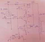
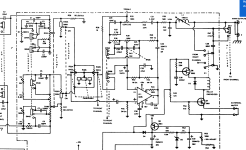
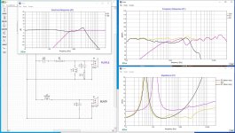
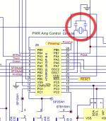
Here's a schematic:
LM386.png


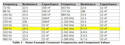
So, first of all, C1, the input DC blocking capacitor. The 10K volume pot in parallel with the IC's 50K input impedance results in 8.3K input resistance.

I'm aiming for Xc lower than 8.3K/10 at 100hz (this is low enough for my application, 20hz seems excessive for me). A 2.2µF cap gives Xc of 0.72KΩ at 100Hz so this seems good to me. This is higher than any other LM386 amplifier design I’ve seen online though (ranging from 47nF to 1µF)?

Next, C2. I went by the datasheet which shows 50µF as the best frequency response (Fig 2. Power Supply Rejection vs Frequency). The graph is for 6V supply though and I’m using 9V so I’m unsure what impact that might have. Again, 50µF is higher than the e.g. 0.1µF I’ve seen elsewhere.

For C3, I’m connecting to a miniature 8Ω speaker (well actually vibration speaker element so a speaker coil driver without the cone). The chip’s output resistance is 0.1Ω so I have a total output resistance of 8.1Ω. To work out the capacitor I’m aiming for Xc less than 8.1Ω/10 at 100Hz. A 2,200µF cap gives me 0.72Ω at 100Hz. This is much higher than used in many other circuit. Size and cost seems a more likely factor behind this and I have seen 2,200µF recommended elsewhere.

C4 and R1 form part of the Zobel network. Rather than take the standard values seen in many circuits (generally 10R and 47nF) I calculated these. My speaker has a voce coil/DC resistance of 7.4Ω. recommended resistor value is this times 1.25 and so 9.25Ω. 10Ω resistor is fine. For the cap the calculation is Le (voice coil inductance) / R (9.25Ω above) * R (well R squared but I can’t do superscript 2). Le for my speaker driver is 0.06mH. I dived this by 1000 to get Henries (and multiplied the result of the calculation by 1000000 to get µF) resulting in 0.61µF. I understand that going higher should be fine so a 1µF cap is an easy value.

C5 and C6 are power supply filtering/decoupling. I couldn’t find a source to calculate this so went with a range of advice and settled on 100µF and 0.1µF.

I’m leaving pins 1 and 8 open as 20 gain should be enough for me.

I’m using the inverting input (pin 2) as it’s suggested that it sounds better.

As my calculations result in some higher value capacitors than I’ve generally seen I’ve plumped for some polarised elctrolytics where I don’t usually see them (C1 and C2) so I’m unsure about polarity here.

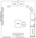
Phew, so that’s the schematic. I’ve also laid out a board design based upon all of this and taking into account best practice I’ve seen. There’s especially an issue with keeping in, out, and power grounding separated and so I’ve done my best here. I’m using non-standard symbols (heavily drawn from Peter Blasser’s paper circuits) but the one’s which should be hardest to figure out are the circles with black triangles next to them. These are for the input and output jack grounds.

Screenshot%202021-01-29%20at%2008.42.22.png


I appreciate that there’ll be a range of factors such as space and cost and so I’m just aiming for something more ‘ideal’ than practical at this stage.

So, anyone who actually understands all of this properly able to comment?

Thanks for your time.

Help with room

I downsized in the last few years to a 12.5’ x 13’ room in our basement. It has a suspended ceiling with the thin plastic decorative tiles in it. Unfortunately this has to be my music and audio room combined and I’m at a loss as to what to do with it. Essentially every square foot of floor space up against the walls is taken up by something so I’m thinking I may have to go near field. No room treatments and I’m thinking about ditching my mostly budget stuff to start over (except my old Polk Monitor 5B’s which are currently getting a complete xover redo with upgraded tweeters - nostalgia). Here’s a close approximation of what I have going on.

Attachments

  • music room.png
    music room.png
    62.8 KB · Views: 149

Amplification strategy for efficient-ish fullrange speakers?

Hey everyone!

Having just started building a new set of speakers, SBAcoustics SB20FRPC30-8 fullranges in a TL/MLTL type cabinet, I now have to find a good amplifier to pair it with. Given that the speakers will be somewhat on the efficient side (92db), I was wondering about what I should aim to feed them with. I've been using active speakers for years so I don't own an amp at the moment. I have access to one of those tiny, awful Nobsound bluetooth amp and that's it.

Since I'll be listening to them at nearfield levels most of the time, only ever cranking them up to reasonable levels once in a while, I figured I should look for something in the 5 to 30W ballpark. I was tempted to just get an off the shelf Loxjia A30 or SMSL A50, but I don't want to be underwhelmed by my new speakers by not pairing them with the correct device.

I've been browsing on here left and right looking for clues but I'm still at a loss.

1) Is it a good idea to pair efficient speakers with something more powerful, say, 100W? Does it mean getting a better, cleaner response and more dynamics?
2) I was interested in the two amps mentionned above because they both have bluetooth, but then, I read in a few places that using bluetooth will sacrifice extensions in both end of the spectrum, is that true?
3) If I were to go with a DIY amp, how easy would it be to work out a competent bluetooth system for it? (I have a USB dongle DAC, but I'd rather go full wireless unless it means too much sacrifices)
4) Is it even worth my while to be looking at building a DIY amp for under 200euros all inclusive? Or will I get similar results minus the hassle by just getting the Loxjie?

I most of all care about resolution and clean bass extension. My entire design choices with the build I'm starting right now are aimed toward that goal.

Thanks in advance for your answers!

Help with small DC offset on output

Fixed! See last post

I've just got hold of a lovely Integra DRX-7 AVR (9.2-channel, class D) for almost nothing, as it was stuck in protect mode. After disassembly (not a trivial task with this beast!) I found one channel had blown its mosfets (IRF6775MPBF, DirectFET Isometric smd package), driver IC (IRS20957STRPBF), burned a couple of resistors and had a suspect input op-amp (TLC071), presumably caused by a speaker short or similar.

I've replaced the faulty components and everything else on this channel measures OK on my DMM as compared with the schematic and a working channel. Because electronic components are very hard and costly to source in New Zealand, so the parts have had to come from Aliexpress.

It now powers up with sound on all channels (yay!), but the faulty channel has a faint audible hiss with a DC offset of around 230mV - not enough to trigger protection but enough to cause annoying pops when changing settings. The poweramp board isn't accessible without complete disassembly, so can't actually test anything on the board while its running.

I've attached the schematic for the power amp section. Can anyone suggest where to start looking for the issue or what/how to test? Maybe Leaky diode or transistor? Or even fake parts?

TIA, Jon

Attachments

Sony PS-333 Turntable - Seeking to Repair

This Sony ES-333 turntable has not been working for some time. I am looking to get back into vinyl again (thread) so that is why I am considering repairing it or getting it repaired.


Today at 1:35 AM Add bookmark #54

This is what I have, or have access to. The Sony PS-333. Everything in that system is called 333. Maybe a repair thread will help.

Just to recap: it was turning fine with the orange light lighting and all that, then it stopped working. No rotation when tone arm was moved. I gave it to an electronics place to repair they could not. Something about replacing the ICs. I wonder now if it was a simple broken contact or maybe even resetting the tone arm. Wish I had it here.

1685595145252.png

Understanding this "Dynaco 6V6 Push-Pull Amp" circuit + cathode bias in the same

Greetings friends. I got a pair of PCBs off eBay that claim to be a "Dynaco 6V6 P-P" circuit and I'm trying to understand how it works, and hopefully build an amp around it. Here's the schematic offered by the vendor:

Login to view embedded media

So a pair of EL84 in P-P, cathode biased, driven by a 12AX7 in a common cathode config, perhaps known as a Floating Paraphrase.

How can I determine the output of this circuit? The PCB has "10W" printed on it...can I get away with a 10w OPT, or should I go beefier? According to Dynaco literature, we're looking at 13.5v at the cathodes, 370 on the plates and a shared 130ohm cathode resistor.

I'd like to build this amp with an ANTEK AS-1T250 PT. It features 4 secondaries total, 2 for HV and 2 for heater power, so I plan to wire each channel with its own windings. Here's a rough schematic:

Login to view embedded media
I'd like to keep the costs down on this one, so the cheaper 10w OPT from EDCOR is more appealing than the 25w model. Obviously the cheapest config would use a single power supply shared between both channels but I can splurge on two, if there would be any noticable improvement. Still cheaper than a Hammond PT and a tube rectifier.

Thanks for taking a look!

Sony STR-6045 - Styrol capacitors

Hi All,

I continue my learning journey into electronic and vintage amplifier. With the help of @Moolie, I brought back to life a Sony STR-6045.

It was all working well including AM/FM except for this little stereo lamp indicator that would not light up.

I traced the problem back to a few transistors when I decided to measure the capacitors in this area while I was at it. There was one capacitor I could not test (the service manual called it “Styrol”). I said to myself, let’s desolder it without investigating further what it was. Stupid me! 😡 I discovered that these Polystyrene caps have very fragile leads and managed to break one.

Sony_STR-6045-Styrol_cap.png


It seems that it can now be replaced nowadays by Polypropylene caps or Ceramic (NPO COG) depending on its usage.

I see a few threads on DIYAudio.com but they are now getting old, so I thought I would ask. My question to you all, is what is it used for exactly and what would you recommend as a replacement?

This styrol capacitor (C320) is on the input of the transformer (T301) on the schematic.

Sony_STR-6045_MPX-encoder_voltages(2).png


Some more details from the manual for those of you interested:

Stereo-mono automatic switching circuit Q304, D303, D304, D305, D306:

This prevents noisy stereo reception by automatically switching the MPX decoder’s operation into the monaural mode.

Noise signals above 19 kHz are extracted from the emitter circuit of Q301 and applied to the base of 0304 through a high-pass filter (L302, C306).

The coupling capacitor C307 filters out audio components so that the input signal is primarily high-frequency noise.

This noise signal is amplified by Q304 to drive voltage doubler D304 and D306. D305 provides positive fixed bias for Q304 through D306 and D304.

When a weak stereo signal or interstation noise is received the output of D304 is fed back to the base of Q304, and drives Q304 into conduction.

This in turn shorts the frequency doubler output to ground through R315, preventing amplification of the incoming signal, and therefore operation of the 38 kHz amplifier and stereo indicator circuit, Q302 and Q303.

When a stereo signal is received, the signal-to-noise ratio increases, reducing the noise signal It the base of Q304. Therefore Q304 turns off and enables the stereo demodulator circuit to operate.


38 kHz amplifier Q302:

The 38 kHz pulses produced by D301 and D302 are amplified by Q3302. The tank circuit at the collector of Q302 is tuned to 38 kHz to restore these pulses to a sinusoidal waveform. This signal is transformer coupled to the bridge type demodulator to supply sampling drive for the demodulator.

STEREO lamp circuit Q303:

The STEREO indicator lights when the FUNCTION switch is set to the FM AUTO STEREO position and an fm stereo signal is received. The emitter of Q302 is connected to the base of Q303 which is normally cut off.

The circuit operates as follows:

When a composite stereo signal is applied to the multiplex decoder, the 38 kHz pulses produced at output of the frequency doubler yield a higher average current flow through Q302. This forces Q303 into conduction, lighting STEREO indicator lamp PL901.

Thank you all in advance for your help and precious advice.

Krell KSA-300S will not turn on

I'm trying to fix a Krell KSA-300S amp. I hope I don't have to ship it back to the manufacturer because it's so heavy. Hopefully some members here can help me troubleshoot it. I do know how to solder.

Sequence of events leading to the current problem:
1) when powering up, it has about 1 minutes of delay before the output relays clicks on.
2) recently, I can hear a "sizzle" sound (like doing B-B-Q, frying beef) when I turn on the power switch. After 1 minute, the relay clicks on and the amp is fully operational.
3) more recently, I hear louder "sizzle" sound when powering up but the amp is still fully operational.
4) most recently, after the above events, the amp will shut down. I'm assuming the protection circuits kicks in to shut down the amp. No speaker damage. This happen one time after the amp has been on for 1/2 hour. The other time, amp shut down after 2 hours. For both times, after waiting for 5 minutes, I was able to turn on the amp again. The weather here is about 90 degrees lately and I listen at regular volume level. The hot weather probably has nothing to do with this but I thought I mention it.
5) last week, when powering up, I think I hear a "crackle" sound in addition to the "sizzle" sound. Amp did power up as usual but after about 1 hour, the amp shut down. After waiting for 5 minutes, this time the amp will NOT turn on anymore.

Questions:
- I understand that capacitors went out very often and I suspect that it's the same situation here. Anybody knows which one(s)? I have not been able to find a schematics on this forum or at the Krell web site. I also suspect that the problem is on the "start up" board and I suspect (& hope) that the amp section are fine. I have done a internal visual inspection. Nothing looks burnt or leaking.
- I have done a search on this forum but I did not find anything related to KSA-300S. Lots of info on KSA-100S though but the problems are unrelated.

Any suggestions? I plan to "dive" in and do some troubleshooting soon.
  • Like
Reactions: tonykara

A monitor for an e-drum kit

My son has been learning drums for about 6 months and so has been rewarded with a drum kit. Thankfully it has headphone output so the neighbours are spared.

Does anyone have any experience with measuring or designing drum monitors.

Based on my limited knowledge of drums, the frequency response should be from 50Hz to 1Kh; with harmonics extending to about 6-10KHz, although cymbals can extend to some 15KHz.

So I plan to try my hand on a 2 way with a 12 midbass and a dome tweeter in a waveguide or compression driver in a horn/waveguide. It’s an excuse to use all those parts on the shelf.

What is the design targets for a drum monitor?

100dB/1m?
105?
110?

2 way?
Coaxial?

Of course for a few hundred dollars there’s the Alexis Strikeamp 12 and Roland PM-200. The specs are geared towards musicians so little is indicated about the performance characteristics. But they have a mixer and equaliser knobs for tone and knowing Roland, probably has FIR DSP, is highly optimised and fit for purpose. And cost optimised for musicians.

Technics cd player output - bypass these (resistors to ground) nor not

My Technics SL-P477a, already happy with it, but since upgrading the rca jacks, i was curious if i could bypass the resistors to ground. I left the compartor opamp in LM833, but changed the other to LME49860. I had old film capacitors sitting around from speakers i once had, so they had some hours on them and used them. I kept the same capacitance on the caps. I was shocked to hear that Elna is no longer manufacturing the SilmicII

Thank you
Sam


P1490182.JPG


bypass or not possible the resistors to ground? if not i can leave it, sounds great as it is. The mechanism cdm4/19 is easy to come by, as i have spares.
P1490188.JPG


P477a.jpg

Thor & ASP1000 -> :-/

My summer house had a brush with a lightning strike some 15 meters from the house. Main incoming fuses was pulverised. One can see how the kA moved on the garden surface (pic). Unfortunately my system was left on and one of my mono power amps was found with the following symptoms:

  • klicking noise every 2 seconds
  • 1,4 V DC on output
  • blue capacitor close to output blown (pic)

Anyone with repair knowledge of this specific product have any idea?


PS: Also a Didden Silentswitcher was put out of service 🙁

Attachments

  • DSC_1286.JPG
    DSC_1286.JPG
    346.3 KB · Views: 103
  • DSC_1291.JPG
    DSC_1291.JPG
    218 KB · Views: 100
  • DSC_1289.JPG
    DSC_1289.JPG
    289.1 KB · Views: 100

DD M4 blown output section

Hi guys on the bench today i have a DD M4
Came in with a blown output section

All fets are blown. I've since removed all output fets. Amp now powers up with no protect. HOWEVER... I'm not getting any drive on the gates (still no fets fitted) (24N40F)

Had a look at driver card and DD have shaved the part numbers off the drivers.

Does anyone know what output drivers these amps use? Also. Are there buffers used in these amps? All part numbers on the driver card have been shaved

Thanks 🙂🙂
20230815_065059.jpg

Need Help Finding Alternatives for BD140-10 and BD139 Transistors

Hi DIYAudio community,

I'm currently working on a DIY audio amplifier project, and I've run into a bit of a roadblock. The transistors I planned to use, specifically the BD140 (PNP) and BD139 (NPN), are unfortunately out of stock and unavailable from my usual suppliers.

I'm reaching out to the knowledgeable members of this community to ask for assistance in finding suitable alternative transistors that can perform the same function as drivers in my circuit. The BD140-10 and BD139 are critical components for the project, and I want to make sure I choose replacements that will work seamlessly.

If anyone has experience with this situation or has worked with alternative transistors in similar applications, I would greatly appreciate your recommendations and insights

Question re B&C DCX464

Greetings all,

the B&C website lists the DCX464 as a 1.4 inch/36 mm, cf. https://www.bcspeakers.com/en/products/coaxials-hf/1-4/8/DCX464-8. However, either way I measure it, mine appears to be 1.5 inch or 38 mm. The pictures are just for demonstration, I actually measured it with calipers).

Do I have some rejects, or is it sloppiness in manufacturing/marketing?

Kindest regards,

M

Attachments

  • 20230814_100656.jpg
    20230814_100656.jpg
    629 KB · Views: 98
  • 20230814_100618.jpg
    20230814_100618.jpg
    493.7 KB · Views: 80

Another Balanced Microphone Pre-amplifier

I want to design low noise balanced dynamic microphone pre-amplifier, but cheap enough with easily to find component in my country.
I use 2SB737 transistor which have very low rBB, but I'm not sure how much collector current to get lowest noise for 150 Ohm output impedance dynamic microphone.
In this simulation, the collector current is 2.7mA and voltage input noise is 1.7179312nV/Hz½ at 1Khz max. gain.
Simulation used ZTX951 because it have slightly lower rBB than 2SB737. I do not have 2SB737 model.
I use NE5532 op-amp because it is cheap. Dual op-amp is easily to find than single op-amp. In input stage NE5532 parallel, so I can used 560 Ohm feedback resistor.

Gain can be adjust from around 7 dB to 60 dB. Is it enough?
And one op-amp use for clip indicator than use for nothing.

Any suggestion are welcome.

Attachments

Help with shipping

I'm wondering if someone might be able to help with shipping a small mono amplifier from the States (Pennsylvania) to Japan? The gentleman I'm buying it from is getting on a bit and unable to take care of the packing for overseas shipping on his own.

Please send me a PM if you might be able to help with this. All costs covered, obviously. I can also return the favor with the purchase and shipping of any audio items from Japan.
  • Like
Reactions: matsurus

Plate Z ruminations

Hello,

A couple of years ago I bought a pair of big mains toroids from a surplus shop with the intention to try them as PP output transformers. The feature that caught my attention was a 37-0-37V low current secondary winding that I intended to use for CFB, cathode feedback. Together with 2*115V primaries and a high current 19V secondary that would make a 2k:8R OPT with ~25% CFB taps. Practical tests revealed that the transformers worked fairly well although they, as expected, had to be downrated quite a bit for fullrange use.
More about the transformers and my prototype in this thread: https://www.diyaudio.com/community/...ers-as-opts-with-a-little-twist.374308/page-2

As I can remember those transformer did sound quite good and it would be fun to build something with them one day. Sweep tubes would be the obvious choice, either one pair of PL519 (40KG6) or a quad of PL84 (15CW5) per channel as I have plenty of those.
On the other hand I'm getting old (44...) and bored and it would be more fun to build something a bit more... eccentric. I love the look of old 807s and I have a box full of them, including some decently matched quads.
The STC "807 bible" mentions that a pair of triode wired 807s can deliver 15W into 3k p-p at 400V, as seen in the first screenshot. The second picture shows my interpretation of this OP in the vtadiy.com loadline calculator. The third pic shows a 2k p-p loadline at 280V, here the simulator indicates 3,6W in class A1 and 26W in AB2.

AB2 and 25% CFB would require a very serious driver stage, but nothing that can't be done with direct coupled Mosfet followers (PowerDrive) and a much higher voltage rail for the voltage amplification stage preceeding the mosfets. Is this whole idea completely crazy or could it possibly work, perhaps even sound decent?

STC15W.jpg807-3kAB1.jpg8072kAB2.jpg

TPA3116 2.1 Channel BT - Sound cutting every 1s @ low input (video)

Hi,


saw few thread about sound cutting but it was @ high volume.


It was working fine for few weeks, and out of no where, under normal use, the sound is now cutting under low/med signal.


- Mine is at low volume (low signal input), the sound is cutting. see video.
- the 3 channels are cutting in same time.

- If I stop music over BT or Line-in, the speaker are clicking in the same way.


It act just like a overtemp protection, the TPA shutoff and then ON every 1s.


Please, note that the ''shutoff'' click, is way different than the original hiss sound from no signal (battery saver).


Solutions so far :

-I tried many power supplies,
-many speakers (4 to 8 ohms).
- I cleaned the original thermal paste that was on the TPAs legs, put new artic silver.
- Play with volume knobs


Nothing worked.


Final note : if I'm blasting the sound, everything is ok. But its hard for the ears 😀


YouTube


s-l1600.jpg

Flyback diode for relay coil?

Need help with this circuit:
I put together a board to convert a constant 12VDC trigger into a pulse signal to turn on and off an old Classe amp with a RJ12 connection and the circuit worked as promised.

However, I'm wondering if it's necessary to have a flyback diode across the SPST relay coil to protect the electrolytic capacitor and the SPDT contacts.

If the answer is yes, what type of diode should be used? Is it okay to mount two diodes facing each other on the relay coil?

Screenshot 2023-07-31 at 18-03-26 Scheme-it Free Online Schematic and Diagramming Tool DigiKey.png

Amp Layout - mounting Toroids

Greetings, friends, I'd like to build a Power amp with a toroidal PT, the Antek AS-1T250. Amp is based on the Dynaco ST35 with circuits on a pair of PCBs, SS CRC power supply, Edcor CXPP25-MS-8K and everything bolted to an Aluminum top plate:

Login to view embedded media
Toroidal PT will be mounted to the underside of the plate:

Login to view embedded media
Will I have hum with the output transformers mounted in such proximity to the power transformer? Is this baby gonna fly?

thanks for taking a look

will

Two more book recommendations about the history of music recording and the record business, etc.

Installments 4 and 5 of my Tracking Angle series called "A Bookshelf for Lovers of Recordings" are now up.

4 The B Side copy.jpg


#4 is: The B Side: The Death of Tin Pan Alley and the Rebirth of the Great American Song

by Ben Yagoda

Ben Yagoda tries to figure out why the period from the climax of the Great American Songbook era (circa 1945) to the advent of Rock and Roll (1955) was such a Musical Hazardous-Waste Dump (my words not his). The prime example being the fact that “[How Much Is That] Doggie in the Window” spent eight weeks at the top of the Billboard pop chart.

somethingtintheair.jpg


#5 is: Something in the Air: Radio, Rock, and the Revolution That Shaped a Generation

by Marc Fisher

This is a history of pop music from the standpoint of the radio business.

For a while, it looked like broadcast television would put many radio stations out of business, especially because much early network programming consisted of "variety" shows that featured live music. Quoting myself:

"What saved radio was the rise of rock music (indeed, the relationship between local, independent AM radio and rock music was symbiotic); the advent of the Top 40 format; the rise of the Disk Jockey as a star personality; and the opening of the airwaves to previously marginated African-American and Country (Hillbilly) music."

Another very well-researched and enjoyable read.

john

Pure Evoke/Avanti Flow - New Display Module

After needing a new display for my Pure Evoke Flow I found this thread Pure Evoke Flow Internet Radio (please visit the thread to find out about the display and fitting instructions)

I ordered more than I needed from China so that I could get a good price (I hate paying full price for anything!) and so that others could benefit too. They were quickly sold so I got a bit of discount from the supplier and ordered some more.

Now I intend to continue importing the displays as long as there is demand so have created this post in the Group Buy section. Be aware that I am not a vendor or trader, I don't have a shop or any other spares, I am just a private individual helping out 🙂

The new batch are now in the UK and should be with me 12/12/2017 and I will start posting them out as soon as people pay for them.

So - Rather than sending lots of PMs the prices and payment details are:-

1 x display inc 1st class post to UK £18.90
2 x displays inc 1st class recorded post to UK £38.00

1 x display inc tracked post to most of Europe £25.50
2 x displays inc tracked post to most of Europe £43.50

If you are anywhere else please ask.

Payment by PayPal GIFT (to avoid their fee, otherwise price goes up) to :-

ajsprotect-ebay (at) yahoo.co.uk

You must include your full postal address AND your diyaudio username when making payment.

Note - there are 30 displays in this batch with 21 reserved for the following list, the remaining 9 will go on 1st come 1st served basis. If they go quickly I'll start a new list and order another batch.

The list of interested parties so far is:-

elecroly +2
ec1ct +2
Justin76 +1
noigardo +1
Badger +2
Gttnewbie +2
purejon +1
Rowbo +1
Titanium rider +2
Mrg481 +1
Jamie35 +1
Impulse Tryer +2
xtof41 +1
rowers+1
Artimuscrackfrog +1
Projects by fanatics, for fanatics
Get answers and advice for everyone wanting to learn the art of audio.
Join the Community
507,756
Members
7,886,951
Messages

Filter

Forum Statistics

Threads
406,167
Messages
7,886,951
Members
507,756
Latest member
CalmRiver