I recently tried swapping out 65 year old electrolytic coupling capacitors from a Motorola HS 711B stereo tube amp. After installing the new caps on one channel of the amp, I no longer get an audio signal, just static from this channel. Any suggestions for troubleshooting this? It's not a high value amp so I'm only using Orange Drop caps. There are no markings for polarity so I'm not sure if that's going to make a difference here.
Use your scope and signal trace, both before and after the coupling capacitors.
Polarity won't be an issue with the film capacitors.
Polarity won't be an issue with the film capacitors.

Do you have a multimeter?
Check the connections of the cap to the other parts of the circuit, there may be a break somewhere.
A schematic and/or a pic of the connections close up might help.
Is it a PCB or point-to-point?
Jan
Check the connections of the cap to the other parts of the circuit, there may be a break somewhere.
A schematic and/or a pic of the connections close up might help.
Is it a PCB or point-to-point?
Jan
Can't see nothing wrong, unless there'ss a short to another wire, hard to see, but you probably checked that.
If both channels have the problem, there's something else wrong, not the caps.
Anything else that might have been changed, even inadvertently?
Are you sure there's signal coming out of the source?
Did you temporarily disconnect power, or removed a fuse, and forgot to put back, that sort of thing?
Can you see the tubes glow?
Do you have a multimeter?
Diagnose!
Jan
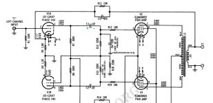
Check the value of R17-R19 (100 ohms resistors on pin 2 of the output tubes). One of them looks discolored. They may open if the tube is faulty (internal shorts) or, on this kind of sockets, if the tube is inserted in a wrong way,
That's it, obviously. Have a close look at the photo. There's no pin of neither tube inserted into the contact where the capacitor is soldered to.
Berst regards!
Berst regards!
It looks like a tube pin contact but it is a tie point instead. The wafer on the top side of the socket does not have a hole in that position, or at least should not have it.
pcan is correct - The pin configuration of the tubes will not allow them to go in any other than they are. Additionally, they are aligned the same way as the other channel (which works fine).
Last edited:
All the tubes glow, have triple checked for shorts. I do have a multimeter. Going to test the suggested resistor. Anything else?
The standard practice is to measure the voltage from each tube pin to ground. Comparing the results from one side to other should show up what might be wrong.
Personally I would bet on either accidentally changing the prior connection or a cold solder joint.
Easy to reheat the bad side capacitor and add a small bit of fresh solder to each joint.
Murphy’s law however is quite clear. The new failure has nothing to do with what you changed!
In the picture it looks like the top 100 ohm resistor is bad. You can test the value with the power off overnight and compare it to the other channels 100 ohm resistor.
The other issue is the bottom left new capacitor solder joint doesn’t look bright and shiny.
Last edited:
Yes, it's easy to be fooled by images but the soldering on both replacement caps just doesn't look good enough, whether it makes electrical connections or not. I imagine that the new work hasn't received enough heat and flux to flow the solder properly and make nice, shiny fillets which show good solder flow and adhesion to the wires etc. If you have used lead-free alloy solder instead of 60/40 for example, that requires a higher temperature which might explain the problem.
The originals were "electrolytic coupling capacitors", I thinl not. They are drawn as the old days used to. The ) side is the outer of the winding and the | side is the inner for noise and hum pickup reasons.
They were Paper.
Resoldering/desoldering components, especially Carbon Composition resistors can seriously damage them.
You have two channels, one good one bad. Compare the voltages when on and measure the resistors values when discharged.
They were Paper.
Resoldering/desoldering components, especially Carbon Composition resistors can seriously damage them.
You have two channels, one good one bad. Compare the voltages when on and measure the resistors values when discharged.
- Home
- Amplifiers
- Tubes / Valves
- No audio signal after swapping capacitors