Hi all,
I had a fairly hot running LM317 due, mainly, to a small heatsink. I mounted it on the chassis instead and noted that there was a negative voltage on the chassis.
Power supply gives +/- 15v
I noticed that the negative voltage (-13.8v) was registering when I had the DMM probes on the power supply ground (black) and the chassis earth (red).
So even though the regulator was isolated from the chassis, the chassis was still measuring -13.8v, when measuring power supply ground and the chassis.
Is this normal? do I need to connect the power supply ground to the chassis earth?
Any help in resolving this mystery would be greatly appreciated.
OK,
So, I connected the power supply ground to the chassis bus earth and now no negative voltage on the chassis.
I may be stupid, but at least I am finishing off this thread (consisting of two posts, both of which are mine)
So, I connected the power supply ground to the chassis bus earth and now no negative voltage on the chassis.
I may be stupid, but at least I am finishing off this thread (consisting of two posts, both of which are mine)
Well, I spoke (wrote) too soon.
The opamps burnt out.
It wasn't a hum all I noticed was a negative voltage when I used the meter on the power supply ground and then the earthed chassis, it was measuring -13.8v.
I connected the power supply ground to the chassis earth, as well as the preamp, and then the reading was 0v. All was well i thought, then after a couple of minutes one of the opamps starting smoking.
Last edited:
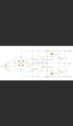
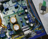
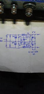
Circuit diagram and photo attached. Only difference is I'm not using a centre tapped transformer.
The power supply seems to be working fine, +/-15v or so, stable. It's just when I attached the ground of the power supply to the chassis earth, the opamps smoked.
The preamp, with the opamps, is ESP P97 (Elliott Sounds).
Everything was working perfect before, other then a hot lm317 so I mounted it on the aluminium lid.
Attachments
Last edited:
What do you mean by, you are not using a center-tapped transformer?
That is necessary, unless there are two isolated secondary windings instead,
each with rectifiers and regulator. Post the correct power supply schematic.
That is necessary, unless there are two isolated secondary windings instead,
each with rectifiers and regulator. Post the correct power supply schematic.
I find it odd an LM317 was hot while just powering opamps. Was it just one of the two that was hot? Sounds like a low resistance path somewhere, and there shouldn’t be -13.8V on the chassis ground. It should be minuscule, like 0.1V, if anything.
What is that stuff under the LM317 - is there an insulator pad or is that some type of grease?
What is that stuff under the LM317 - is there an insulator pad or is that some type of grease?
Heatsink tab is connected to pin 2 = V out.
Heatsink tab must be isolated.
Always read the datasheet.
Heatsink tab must be isolated.
Always read the datasheet.
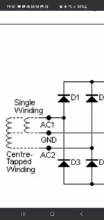
Yes, two separate secondaries, but single rectifier though, as this extract from ESP site (single winding)What do you mean by, you are not using a center-tapped transformer?
That is necessary, unless there are two isolated secondary windings instead,
each with rectifiers and regulator. Post the correct power supply schematic.
Attachments
4 opamps in total, plus 5 LED's. The heatsink was very small, + hotter than - (LED's).I find it odd an LM317 was hot while just powering opamps. Was it just one of the two that was hot? Sounds like a low resistance path somewhere, and there shouldn’t be -13.8V on the chassis ground. It should be minuscule, like 0.1V, if anything.
What is that stuff under the LM317 - is there an insulator pad or is that some type of grease?
Under the lm317 there is isolation pad plus heatsink compound.
Heatsink tab was isolated I checked with a meter and it was isolated.Heatsink tab is connected to pin 2 = V out.
Heatsink tab must be isolated.
Always read the datasheet.
The lm317 is on the chassis lid, the lm337 on on the board with a small heatsink.
Last edited:
I use the BD139/140 each on 25x34mm heatsinks to power 15x opamps at +/-17V, 4x relays at +12V and 2LEDs at +2.2V. Doesn’t get hot.
There is something drastically wrong somewhere if an LM317 is that hot.
There is something drastically wrong somewhere if an LM317 is that hot.
It wasn't drastically hot, it was running OK for 12hrs a day for 2 yrs with no issues, it's just that I wanted to keep things a little cooler. Doing the touch test, it was too hot to keep my finger on after about 5-6 seconds or so.There is something drastically wrong somewhere if an LM317 is that hot.
Well, that’s good to know.
If -13.8V voltage on the chassis appeared after the regulator was mounted, I would check the pad. I guess an important question is, what’s the voltage on the chassis when the regulator isn’t mounted to it?
If -13.8V voltage on the chassis appeared after the regulator was mounted, I would check the pad. I guess an important question is, what’s the voltage on the chassis when the regulator isn’t mounted to it?
Not a working schematic. Needs 3 leads from a CT secondary to function.
Also draw the actual transformer secondary winding(s) exactly as they are connected.
Schematics are topological only, so exchanging the caps and diodes is meaningless.
Also draw the actual transformer secondary winding(s) exactly as they are connected.
Schematics are topological only, so exchanging the caps and diodes is meaningless.
Last edited:
When I place the multimeter (black) on chassis earth, then the chassis lid (where the reg is mounted) it was 0v (obviously)Well, that’s good to know.
If -13.8V voltage on the chassis appeared after the regulator was mounted, I would check the pad. I guess an important question is, what’s the voltage on the chassis when the regulator isn’t mounted to it?
When I placed my multimeter (black) on the power supply ground, then red on chassis earth I got -13.8v (?)
Yes, I thought to correct it only to show exactly how it is.Schematics are topological only, so exchanging the caps and diodes is meaningless.
Please see this link to the ESP website, P05 power supplyNot a working schematic. Needs 3 leads from a CT secondary to function.
Also draw the actual transformer secondary winding(s) exactly as they are connected.
https://sound-au.com/project05b.htm
Mine is wired exactly the same, the single wired option, no CT, see schematic and text below.
You can have one of the following:
one secondary (or two secondaries in parallel) , and one output voltage
two secondaries connected in series, using a wire from the center connection, and two output voltages
two separate secondaries each with rectifier and regulator, with outputs in series, and two output voltages.
Without a complete, correct schematic of what you have, it is not possible to determine whether it can work.
ESP has no"single wired" option. Do you perhaps mean "single supply"? That only has one output voltage.
Last edited:
- Home
- Amplifiers
- Power Supplies
- Negative voltage on earthed chassis


