Thel Negative low noise PSU

For sale a Thel-Germany low noise Psu up tu 10A and 100V.
Verry little use and top condition. Iv used this for negative bias voltage supply on my EL34 tube amp. But you can use this also for other project. Price would be 40 euro plus shipping 8,90 euro inside EU. Payment paypal for friends.

Attachments

  • IMG_20230327_105148.jpg
    IMG_20230327_105148.jpg
    410.3 KB · Views: 88
  • IMG_20230327_105215.jpg
    IMG_20230327_105215.jpg
    335.9 KB · Views: 92
  • IMG_20230327_105211.jpg
    IMG_20230327_105211.jpg
    352.1 KB · Views: 88
  • IMG_20230327_105152.jpg
    IMG_20230327_105152.jpg
    457.3 KB · Views: 86

Does anyone know what this 4-pin power terminal looks like?

I got the SPARK Houston MINI-1998.
However, in order to drive this amplifier, I have to supply power to the amplifier itself from a separate power supply unit.
The terminals on the power cable that supplies this power were unlike anything I had ever seen before.
I would like to know what this 4-pin, round terminal is and if it is possible to get the same one.
I would appreciate any help from you knowledgeable people.
Thank you in advance.

From Japan
20231020_012407.JPG

MEGURO MN-446A Noise Meter repairs

Hi,
Just wondering if someone might happen to have a Service Manual or schematics for the MEGURO MN-446A Noise Meter please?
I have one of these units and its developed an internal noise fault that is leading to erratic readings.

MN-446A_front.jpg

The new owners of MEGURO DENKI, Japan, no longer carry any information for historic MEGRUO products.
Thanks in advance.
A.

IMG_7225.JPG

IMG_7227-001.JPG

IMG_7229-001.JPG

IMG_7230-001.JPG

miniDSP FLEX 8 with DIRAC Live Transferable License with Free Shipping to US & Canada

I have a miniDSP FLEX 8 with DIRAC LIVE uploaded to make it a "ALL-IN-ONE" Solution for your setup.

NOTE: This price includes the Transferable Direct Live License as it is attached to this Flex 8 Serial Number.

It is a digital preamp / electronic crossover / the best speaker-room correction / Equalizer with FIR capabilities, hence its name "FLEX"

The Powerful DSP Room correction capability is in BOTH Frequency response correction AND to enable time / phase alignment.
It will align the drivers / subwoofers to enable a perfect phase / transient perfect wavefront as validated in REW (Perfect square-triangular impulse response)
With DIRAC Live engaged, the music just sounds right and I believe it's the "Time Coherency" component that makes the music sound dynamic like LIVE MUSIC

Remote with DIRAC / volume / input / mute and other functionality.
USB / Bluetooth / Coaxial / Toslink Digital inputs
8 Analog outputs via RCA
Bluetooth is 5.1 with LDAC with 24/96 capability
Dual ESS 8 Channel DAC IC's used in paired mode for even better SNR (>125 dB)

SOLD to Ferds for $599 USD

NOTE: I have revised my system and require only require 4 Analog Outputs, hence looking at miniDSP DDRC24 or FLEX (2x4 std.) with DIRAC Live currently

SOLD with included insured shipping for US Buyers
SOLD with included insured shipping for Canadian Buyers

Interac Payment for Canadian Buyers
SOLD Paypal Payment for Canadian / US Buyers

Attachments

  • 20231020_181020.jpg
    20231020_181020.jpg
    405.3 KB · Views: 101
  • 20231020_181023.jpg
    20231020_181023.jpg
    338.2 KB · Views: 102
  • 20231020_181201.jpg
    20231020_181201.jpg
    399.2 KB · Views: 74

Noise from tube preamp phono stage - sounds like wind/contact noise on a microphone - can trigger by poking tube

Unit is Audio Research SP10.

Until the unit has had ~20 minutes to warm up, I get intermittent noise out of the right channel that sounds similar to the sort of noise you get when your headphone mic is rubbing against your clothes, or wind is hitting a microphone. I can also cause the noise to happen directly by poking or gently pushing the first tube in the right channel of the phono stage. I have tried applying contact cleaner to the tube sockets.

I'm wondering if this is dirty sockets, old/failing tubes, or something else entirely?

Ford Ranger Project

Hello! I'm new to this forum and was hoping to get some guidance and hopefully a more experienced perspective of where I've gotten in my plans.
I have a 2002 Ford Ranger with a 2 door extended cab. I've already installed an upgraded head unit and plan to move on from there. Yes, I will be doing a big 3 upgrade. Considering using a Mechman 370A alternator. I intend to use Siless Hybrid 3in1 200 mil sound deadening material on the floor, roof, doors, and walls.
Goal is a SQ focused build. Not completely ignore SPL, but SQ first.
I'm planning on using dual 6.5" speaker pods and installing Dayton Audio RS150P-8A wired in parallel for a 4Ohm load, using a bandpass first order crossover at 200Hz and 4kHz. The tweeters will be Dayton Audio AMTPOD-4 wired inverted, with a first order high pass at 7.5kHz. Not sure what I'm going to use for the rear channels. Considering PRV Audio 6MR250B-4 SLIM speakers for the rears, but can't seem to get XSim3D to cooperate when they're plugged in. For a sub, I'm planning on using a single Dayton Audio UM10-22 in a 17"x18"x7" (external dimensions) sealed box, deleting the fold down seat behind the drivers seat.
Screenshot 2023-10-20 174344.png

Now to avoid having to come up with passive crossovers, I'm intending to independently amplify the front woofers, rear speakers, tweeters, and sub using a Down4SoundJP77 mounted to the panel that runs along the back wall under the rear window. Yes, to avoid the complication of multiple amps, I'm planning using a single amp solution. That's probably my one reason for doing so.
Going by the appx .944 cubic ft interior volume (not accounting for volume the driver will take up), I'm looking at an F3 of ~30Hz and F10 of ~21.76Hz while peaking around 48hz(appx +4db), not accounting for cabin gain and never needing to set a subsonic filter as it should never hit XMax (hitting 15.933mm peak at 38.15Hz). This is assuming wiring in series for a 4Ohm load and full 500W RMS signal.
Screenshot 2023-10-20 180446.png

Screenshot 2023-10-20 180417.png

Here's the graph I was getting in XSim3D without the rear speaker, assuming 100W out of the amp, no PEQ, and filters mentioned above (sub low pass set to 200hz, again first order, all Butterworth).
Screenshot 2023-10-20 171514.png
Screenshot 2023-10-20 171531.png

If you have some constructive advice or pointers, please feel free to tell me. I'm not against doing a double baffle on the sub box, just didn't do it on the original design plan.

Edit: I apologize if this is in the wrong section.

A variant on Driver Mounting

Last year I put together 4 Nostromo speaker (Alpair 11MS) in the smaller of the three design sizes configured for amplifiers with relatively lower output impedance the the two larger configurations.

Two were sent to a nephew as a gift on completion of his bachelor's degree, and we kept two, which I have enjoyed very much. I decided to build another as a center channel for use with Schiit's newly released preamp, the SYN, which contains an active implementation of what first saw the light of day around 1970 as David Hafler's DynaQuad.

For this third Nostromo, I thougt I'd try a different approach to the chamfer on the back of the baffle around the driver. The cabs I built last year were chamfered with my router leaving bosses at the screw locations for the mounting screws to bite into. The ususal way of doing things.

This year, I cut out the fronts from my last chunk of 3/4" baltic birch, and then marked locations of the screws where I then drilled 1/2" holes from in the rebate area to the back.
2023drivermount1.jpg

The baffle is sitting on the back of the box, but is not attached. The sixth circle on the rebate is a router burn mark that cannot be felt, so will have no effect.

After that, I routed the chamfer all the way around the back, followed by gluing in five smooth dowels a bit more than 1" long.
2023DM2b.jpg

I'll make sure the mounting surface is smooth for the gasket, drill the dowels for the mounting screws. The chamfer is about 7/16". I'll need another bit to get a deeper chamfer.

The result should let the driver breathe just a bit better, and I'll have longer screws biting into the wood over a greater length. That should allow more cycles should I want to remove the driver and replace it after making a modification or repair. I don't expect to hear a difference, or expect to have any "proof" of superior performance. Just thought it would be fun to do.

Skip

PASS preferred resistors

Hi. I'm gonna need some guidance here. I'm trying to find the preferred resistors used by the man himself and PASS LABS.

I have tracked down the 3W part which sits on the output stage, this is the Panasonic ERG MOX resistor, but when it comes to the others, I am a bit lost, but I have have an alternative. I am thinking of Amtrans AMRT Carbon Film Resistors. Vishay mrs25 can also be an alternative.

Can someone jump in an comment ?

Attachments

  • image_2023-08-18_220859645.png
    image_2023-08-18_220859645.png
    22.2 KB · Views: 243

An Experiment in Phantom Center bears fruit!

So I’ve been home and self quarantining for the past few with Covid in my dedicated two channel room….couldn‘t be without music as I convalesced. But of course, there’s a big screen in there and revisited the classics. First just stereo…..nope…..separation at 8ft between left and right was too distracting. Turned on PCM in for 5.1 and then deleted the center and surround output…..Better but not ideal. Grabbed a retired Polk center channel……one of the typical MMTMM things……..aweful!…..worse than either no center or phantom. Voices locked to the screen but only the screen and male voices sound like am radios…….nope.

Did some googling and came across the old Dynaco differential thing. So I tried it and forgot I had the phantom center set……..left a big hole in the soundstage and left and right imaging collapsed. Hmmmmmm. So instead I took the left positive and the right negative and BINGO……that did it! Dialogue returned to the screen and intelligibility was the best of the attempts. Voices now have weight with support from the left and right channels…….this setup will stay for theater use for sure.

Now this only likely works as the crappy center is terribly inefficient co to my mains at 4ohms and of course, for two channel I’ll just disconnect it and go back to Analog direct into my preamp.…..and a full large 3 way Center would probably be better……but for those that are challenged for space to fit a true center or the desire to add an ugly box to their room ( that’s me), then I count this little accidental experiment as a huge success.

Acceleration Factor

I'm in the brainstorming phase of a new speaker build which lead me to create an excel sheet with those accelleration factors including matching factor.
I thought i can share it to you.
Source of the Accelleration Factor:
Motor acceleration 'Γ' in moving coil loudspeakers

And here is the sheet

the prices are taken from soundimport , so you might get it cheaper somewhere.

Edit: i did filter it by the Sd value. so dont wonder why the manufacturers are mixed up

Any new developments in CD format?

I must be getting old or stupid, or out of touch. I thought cd is cd, that is compact disk for two channel audio encoded in 16bit pcm at 44.1kHz sampling rate. At least that's what i learned at school.

I know that there were attempts in the past to improve the cd. I do have hdcd player, and lots of hdcd disks (compatible with normal cd player), which were 18bit, hence better. Many Joni Mitchel's cds were hdcd, i have most, and they do sound better, if you have player. Mr windows big gate killed the hdcd.

I never invested in DVD-audio format, since i hate how slow the dvd players are due to watermarking...loading, loading, loading, eff that.

Even Super Audio CD was big flop. Mixed at cd format, but not compatible with anything. Dead child.

Now i came accross this cd in my collection, it has too many stickers. Does not sound any better than average cd. So it has compact disk CD logo, SACD logo, Multi-ch Stereo logo, Hybrid multichannel 5.1 logo, and finally DSD Direct Stream Digital logo.
Only shiityy THX logo is missing, just kidding.

Is this the pinnacle of digital disk evolution?
What is DSD? Anyone have 5 ears to appreciate 5.1 channel? What's next?

Attachments

  • 20231016_131343.jpg
    20231016_131343.jpg
    392.6 KB · Views: 185

How to disassemble a AT-1100 MK lll tonearm?

I am rebuilding an AT-1000 MK lll tonearm. Disassembly was straight forward until I got to the bearing cups. They take a tiny U-shaped tool to unscrew and it seems impossible to find the right size. I tried taking two sewing needles and gluing them onto a small wooden stick, but the needles broke before the caps unscrewed. Does anyone have any suggestions?

What if the second peak of a ported box resonance is being absorbed considerably?

Consider the impedance peaks one is port resonance and another woofer resonance in the impedance curve when loaded in the box. Now what happens if you absorb considerable like 80% of the woofer resonance which is second peak of the impedance graph.

First question is : Does it needs to be there? Secondly consider a magic absorber material is there to absorb the peak energy in the second peak frequency then would that be good? what are pros and cons of absorbing the resonant peak at the second peak? in the link provided for reference: http://archimago.blogspot.com/2019/08/measurements-speaker-impedance-part-2.html

Attachments

  • por.png
    por.png
    87.5 KB · Views: 85

EnABL - Listening impressions & techniques

This thread is a continuation of the EnABL Processes thread here:
http://www.diyaudio.com/forums/showthread.php?s=&threadid=100399&perpage=25&pagenumber=1


This thread is for listening impressions and questions concerning applications. This is not to contain the technical side of things. Those posts will be deleted. The thread for that is here:

http://www.diyaudio.com/forums/showthread.php?s=&postid=1460032#post1460032

Throat Microphones with Behringer UMC1820 -> do I need a preamp?

Dear community,

I have quite a tricky question. I am using five Retevis EAL002 throat mics to pick up breathing sounds for a collective experience. As I am using the Behringer UMC1820 for my sound installation I have soldered mono jacks with 3.5mm to the throat mics so I can plug them into my interface. Unfortunately something seems to be off, the voice being picked up is very low and it also creates a very high and loud noise. Also pressing "inst" and not pressing "pad" does not help. I guess I am in need of a preamp. I have looked a l ittle bit into DI boxes, for example the "DBX DI4 active four-channel Direct Box with line mixer". But I guess it's not really what I am looking for. I have no experience and knowledge about these devices therefore I was wondering if someone here has some better suggestions for preamps/di boxes. Thank you so much!

Best,
SonicDriver

Huge WE announcement!

Watching this morning, Login to view embedded media
According to an interview in https://guitar.com/features/intervi...ic-confirms-plans-tube-georgia-factory-crisis

March, we will increase its offerings to include 12ax7, 12at7, 6L6, 6V6, el34, KT88, EL84, etc.,

I suggest all goto the contact page and thank them, and let them know what tubes you would want !

For Sale Technics EPA 100 tonearm for repair

* SOLD * I have a Technics EPA 100 tonearm with badly worn top and bottom bearings. The left and right bearings aren't as bad but will need work. Its a long story but I ended up buying 2 EPA100s, both I was assured were working perfectly but wouldn't play a full LP when I got them. The second arm was disassembled by a Techie who tried to help, so its all in pieces. As a sweetener I will include all the bits except the mount, arm wand and counterweight from the second tonearm. I will keep them as spares for the arm I bought from Samurai. The headshell is not included and no cable either.
The arm lift has been removed and is at the side of the arm in the first picture. The arm clip is broken but the piece can be glued back on or replaced with an SL1200 clip. It was actually broken in front of me by the clown who I bought it from.

I am in Perth, Western Australia. Looking for offers. I don't expect Samurai prices but don't want to give it away either. I was quoted up to US$600 to refurbish.

Attachments

  • IMG-20230125-WA0000.jpeg
    IMG-20230125-WA0000.jpeg
    257.2 KB · Views: 252
  • IMG-20230125-WA0002.jpeg
    IMG-20230125-WA0002.jpeg
    397.4 KB · Views: 203
  • PXL_20230125_055011085.jpg
    PXL_20230125_055011085.jpg
    726.5 KB · Views: 211

I want to combine these 2 circuits, is this possible?

First off, I am a complete newbie to electronics as well as audio engineering so please keep that in mind.
The first circuit is from: https://tataylino.com/guitar-preamplifier-circuit/. This is the guitar preamplifier.
The second circuit is from: https://www.ti.com/product/LM1875
1. Here is the preamplifier:
1697687077451.png

2. Here is the amplifier:
1697687096396.png

I would also like to know a few things. If they are able to be combined, what would power them? I was planning on powering the preamplifier circuit with a

9V DC Wall Power Adapter, but I have no idea how, once combined, to power the entire system. Any and all help would be greatly appreciated.

Soundstream XXX-4000D Tarantula

Hello everyone.
I new on this forum and i would like to ask if someone could help me with this chinese copy of korean board.
It's arrive with all power mosfets burned also 3525 was burned, i replaced all power transistor and IC and it start to power on, but after it start to have anomalies with a sound,( only half sinus wave is out) and something strange with a power supply.
There are some measure that i take maybe someone can understand whats going on with this amp.
Measurements from central GND. Dc supply on 13.1V. Measurements without driver board.
IC 3525: IC393
Pin1: 0 V Pin9: 5.20 V ---??? Pin1: 8.3 V
Pn 2: 4.73 V Pin10: 0.05 V Pin2: 2.4 V
Pin 3: 0.01 V Pin11: 3.7 V Pin3: 4.3 V
Pin 4: 0.47 V Pin 12: 0 Pin4: 0 V
Pin 5: 1.89 V Pin 13: 9.37 V Pin5: from 2.6V and growning up Why???
Pin 6: 3.40 V Pin 14: 3.7 V Pin6: 2.37 V
Pin 7: 1.82 V Pin 15: 9.37 V Pin7: 3.5 V
Pin 8: 4.50 V Pin 16: 4.73 V Pin8: 4.7V

Also i measured optocouplers and have some strange dates: (mesures were done between pin)

Ic 303 Ic304
1-2: 52V ??? 1-2: 1.3 V
3-4: 0.2V 3-4: 1.08 V
5-6: 5.6 V 5-6: 0.24 V
7-8: 4.8V 7-8: 4.7 V

I have tooked also measurements from driver connector (without driver board, central GND as point). Seems something wrong with negative rail.

Vnn: -109.2V ?? -15: -14.57
Drv: -109.2V ?? +15: +15.00

VPP: +129V ??

Also R330 is very hot and when i try to touch it with multemeters probe i start to hear some noise from power transformer ???

I hope someone can help with this issue.

Attachments

  • Tarantula.jpg
    Tarantula.jpg
    608.5 KB · Views: 171

Goodmans driver question

I've got a Goodmans XO 950/5000-2 crossover, a midax, a trebax and two 12" 8 ohm RCA woofers from a 1960's console that I'm going to try building a speaker with.

I never could afford an appropriate Goodmans driver back when I bought the midax (got three) Trebax (got two) and crossover (got two) so they sat for several years until I got the RCA woofers a few years back and casually experimented with them.

I put the woofers in series for a 16 ohm load as the other drivers I believe are 16 ohms.

I do not have the attenuators that could be used with these.

The midax and trebax are louder than the woofers and the trebax is a little louder than the midax.

Three questions.

1. Do the capacitors in the crossovers need to be replaced?
2. Are there 16 ohm variable l-pads or is there a schematic of the original attenuators so I can duplicate them?
3. Would it be better to pass these on to someone who can use them with a proper Goodmans woofer?

Linear Audio Autoranger - Populated Boards / Tested / Not Calibrated

SOLD

I have a spare set of fully populated and verified working Autoranger boards; the control board and the attenuation board. The firmware version is V1.5. These are the original boards / design.

Price / Payment / Shipping - $100 USD PayPal net to me. If I arrange shipping, buyer covers shipping at cost using UPS or USPS. Buyer can also PM me a pre-paid shipping label for USPS, FedEx, or UPS. I will provide shipping weight and dimensions along with other necessary details.

https://www.linearaudio.net/la-autoranger

The boards are tested and work properly. The system is not calibrated. You will need to do that if you choose. Per the manuals, it is functional 'out of the box', and I've found it to be so. The displayed voltage is slightly off (expected). I think most people would likely do the simple Accuracy calibration and CMRR checks and leave the FR alone.

Why did I not calibrate it? It's not necessary (to me). The voltages are close enough, and who knows... my hand-held DMM may be less accurate than the Autoranger. 🤷‍♂️

Will I calibrate it for you? I'll do the accuracy calibration and CMRR check for an additional $50. Why so much? B/C I don't want to take apart my other unit, and it takes time I don't really have.

Why am I selling these after so recently getting them and at less than the cost of the parts...? tl;dr - I wound up building two sets, and this community has been exceptionally kind, particularly Jan.

What else is needed to have a fully working Autoranger? A PSU, a chassis, and appropriate wiring.

PS - The display color is set to purple... b/c I like purple. Feel free to change it with the jumpers.

Attachments

  • IMG_4239.JPG
    IMG_4239.JPG
    443.2 KB · Views: 126

I wish they would invent….

A foot switch for the computer keyboard. Press it with your foot and it presses the SHIFT key.

All the GD rules they make for secure passwords require TWO hands to enter them, and nowadays it is F ing constant. What do you do when one hand is full or otherwise occupied? You have to put it down to enter that stupid password again. The foot switch would allow it to be done one handed again, like in the days when it was all lower case. And still be “secure”.
  • Like
Reactions: dkfan9

For Sale Large Heatsinks for Class A projects

I have realized that it is unlikely that I will be as active in this hobby as I once was, so will start listing parts for sale here in the coming weeks. First up is my collection of large heatsinks that I collected for Class A projects but never used. I'm sure I paid too much for some of these, so will probably end up selling at a loss despite increases in metal prices, but such is life.

PayPal is probably easiest for payment. Will ship within the US at buyer's expense; contact me with your ZIP code for a quote. Will consider shipping to other countries, but shipping may be prohibitively expensive. Local pickup in western Illinois is also a possibility, as is meeting part way of schedules line up to allow travel.


Lot #1: pair of silver heatsinks which do not appear to be anodized. The bases look polished, and the fins are maybe oxidized aluminum instead of anodized. Fins are "serrated" for increased surface area and better dissipation. Some holes drilled and tapped in base. Each sink measures about 10.25" wide, 9.875" high, 3.125" deep, with a 0.625" thick base, so the fins are about 2.5" tall. Each sink weighs about 13 pounds. Each sink has small cutouts at the bottom of a few fins as shown in pictures. These were very expensive when I bought them because of their size and weight. Asking $75 for the pair. SOLD

Lot #2: pair of black anodized heatsinks which appear to have been salvaged from an amplifier chassis. These have some channels cut in the top and bottom for mounting. Some holes drilled and tapped in base and some scuffs in the anodizing. Each sink measures about 10.25" wide, 8.125" high, 2.625" deep, with a 0.625" thick base, so the fins are about 2" tall. Each sink weighs about 11 pounds. Asking $65 for the pair. SOLD

Lot #3: pair of clear anodized heatsinks which have done holes drilled and tapped all the way through the base and fins. Good shape overall with the odd dent or scratch here and there. Each sink measures about 9.75" wide, 9.875" high, 2.25" deep, with a 0.25" thick base, so the fins are 2" tall. Each sink weighs about 5 pounds. Asking $35 for the pair. SOLD

Lot #4: three black anodized heatsinks which have a grid of holes drilled and tapped in the base. Some scuffs and fins on the sinks. Each sink measures about 7.875" wide, 5.875" high, 1.5" deep with a 0.375" thick base, so the fins are about 1.125" tall. Each sink weighs about 3.5 pounds. Asking $25 for all three.SOLD

Please see pictures in subsequent posts for details about each lot. Note that measurements are rounded to the nearest 0.125" for simplicity and weights are approximate as my scale's accuracy is questionable.

TL (?) speaker enclosure vent slot questions

A friend of mine is planning on building enclosures for his Lii audio fast 10 drivers. He asked me about the enclosure design, and I could not give a good answer but suggested I'd try to ask here. These are probably very trivial questions for most of you.

Firstly, with the design below, would it be possible to place the vent hole at the backside...? I assume no, but would like confirmation.

IMG-20231019-WA0021.jpg

Secondly, are there supposed to be sidewalls to that vent slot? My friend made some nice renderings to explain the alternatives. So should it be like this:
IMG-20231019-WA0022.jpg
Or like this:
IMG-20231019-WA0023.jpg

Thanks in advance!

Advice on Sony 3 way speakers without crossover

Hi guys, it's funny how our interests come and go and then come back as years pass by, and I've been on many journeys since I last posted on this forum.
Any hoo, I hope I'm posting in the right place here.
I purchased a pair of pre loved Sony SS-S9 6 ohm 120 watt speakers cheep $20 for the purpose of setting up a class D blue tooth sound system for my Daughter and Son in law.
I use the same amp on my old floor standing Sansui 3 way speakers and they sound wonderful, however I was very disappointed in the performance of the Sony speakers.
There is no brightness to them at any volume. very little high's and mids. These speaker had some good reviews in the past so I expected a little better. I disassembled one of them to find no crossover at all. I'd like to see if I can bring some life into them in a minimalist sort of way. I have to admit that I'm struggling with the whole crossover design thing. I can understand how a crossover can be designed around speakers with known values, but I don't get how one can work around a 3 way speaker system with no data. In fact I don't even get how one can purchase a generic crossover to work on un known speakers. I've spent the last couple of weeks trying to answer these questions for myself with no satisfaction.

The Sansui speakers I use are 40 year old S-915 8ohm 120 watt. They kick ***.
Any input would be greatly appreciated,
regards to all,

Walt.

Attachments

  • Sansui Speakers.jpg
    Sansui Speakers.jpg
    83.1 KB · Views: 346

small high sensitivity two way

I know....I can have small .......or high sensitivity...

I have a few tube amps (PP and SET) ranging from 2W (Tubelab SE) to about 14W (PP triode EL34's) and I'm currently using Tang band W8-1772 full range drivers in bass reflex enclosure.

Before these I had some Fostex 207's in a half chang enclosure.

Both of the above are obviously floor-standers...

They sound quite good although I usually end up using a powered 12" sub for some bass augmentation.

..so if I'm running the sub-woofer anyway, I'd like to try some ribbons in a small enclosure; something without whizzer cones too....

I have a pair of Fountek Neo CD 3.0 ribbons that I would like to build with a small (4"-5") mid-bass or full range driver and need some suggestions...

So far I'm considering the Tang Band W5-2143 full range driver...perhaps MTM?

Tang Band W5-2143 5" Paper Cone Full Range Driver 8 Ohm

or the Audax 13LB25AL full range

https://www.madisoundspeakerstore.com/pdf/13LB25AL.pdf

My thoughts are run the 5" driver full range and a simple 1st order on the ribbon crossed over quite high.....

The Audax is intriguing since it's 96db sensitivity .....gives me a little headroom to burn up doing BSC, etc

Thoughts? Issues with this approach?

Wilmslow Classic Floorstanders Project

So, my last post was three years ago, and the Dynaudio TL project in my avatar is long gone. For the last couple of years I've been listening to a pair of Mirage M3Si's I rescued from a skip and rebuilt, and slowly putting together a front end to feed them. The Mirages are now gone as my good lady thought they were too big for the current house (which they absolutely were) and we're aiming to downsize.

My DIY skills are enthusiastic and knowledgeable but lack any real ability, so I’m keeping myself sensible as to what I take on. My mantra for the whole system has been “Grand Enough for Spotify”. Every time I think about spending money on “Audiophile” stuff, I go back to the Mantra… the “Grand” is the nominal budget for the whole system. Source material is Spotify Connect only. I stopped kidding myself I needed any other source when I realised I couldn't hear anything over 11kHz anyway. 🙄

Front end consists of a Raspberry Pi (3B+) with 7”screen and a HifiBerry Digi2 Pro HAT, running Volumio. The optical output from the HAT goes via an old Musical Fidelity V-DAC and a passive volume control to a power amp using Icepower 300AS1 and 300A1 modules. Total cost of all that is about £500, leaving something similar for speakers. Now, if I’m honest, I should buy myself a pair of half decent standmounts and live with them, maybe with the BK sub I still need to fix, but that doesn’t scratch my itch to spend money unwisely on something unsaleable that I “built myself”.

I've been hunting for something smaller than the Mirages while remaining interesting, and up pops a pair of Wilmslow Classic for sale. I decided they were what I wanted and organised a long weekend with the Mrs at the wrong end of the country to collect them. What are they? A Volt BM220.8 mid/woofer and a Scanspeak D2905/950000 in a very solid, 40l floor-standing tower. Similar to the current SM108 kit from Wilmslow, but in a taller and larger box. I was surprised when I heard them (quietly) in the seller's flat. They sounded like a mini-monitor and had no bass worth mentioning. Of course, I bought them anyway and brought them home - I like a challenge!

Got them home and turned them up, hoping a bit of volume might help, but they only got worse… Playing quietly, they were detailed, clean but somewhat uninteresting due to lack of bass. Turned up they just got harsh, sibilant and generally unpleasant. Without measurements, they seemed to have far too much output in the crossover and lower tweeter range.

I pulled them apart to investigate…

IMG_0677.jpg

Two transistors Hi-Z input/buffer/Di Box schematic?

I want to use guitar with HiFi headphone amps and I need to make hi impedance input circuit. I already made it with a single JFET transistor and it works perfect, but I want another version with a bit more available gain, right about two stages, that seems like optimal gain reserve.

I already built it some time ago, with this circuit I found on Google images and I remember I had a lot of trouble getting it to work and to find optimal bias points and at the end I couldnt make it, I ended up with circuit that has less gain than single transistor version. So I would like to do it better this time, mandatory JFET at first stage and another JFET or BJT for second stage.

https://www.next.gr/uploads/8/JFETBJTBUFFERSCH.png

https://apocalypseaudio.blogspot.com/2010_05_01_archive.html

For available JFETs I have BF245C and 2N3820, and for BJTs 2N3904 and 2N3906. What circuits do you suggest, I appreciate schematics and links to articles. Working voltage 5-9V single rail.

For the inquisitive full range DIYer

For you folks that want to see how the other half lives, here’s a VERY impressive new driver from Dayton that would be super simple to design your first two way system!

https://www.parts-express.com/Dayto...ure-Series-Woofer-80W-Driver-4-Ohm?quantity=1

Notice the efficiency……even with baffle loss we’re still right around 90db…..easy to drive

And the 30 degrees of axis response?……are you kidding me……ruler flat to 3khz

Marantz 2325, fully rebuilt to OEM specs...

I got a Marantz 2325 receiver that I'm thinking of selling.

It was fully rebuilt last year, I got the bag of parts to prove it.

I had a specialist work on it. He took all the boards out, cleaned them, replaced the components as needed, caps, diodes, etc, etc... his replacement of such, ie: caps was done understanding their usage, not your typical "shotgun replacement". The only place where he "upgraded" the caps was in the power supply.

I believe the power transistors are still original.

We found a lifted trace on the FM demux board, so he jumpered it.

Replaced the lamps with somewhat lower wattage to preserve the velum -it's in very good shape. All buttons, slider, knobs work. We couldn't test the Dolby system. Phono preamp works; tuner works, tape monitors work; inputs work; lights work; volume and balance work...

In essence, my instructions were to rebuild to factory OEM spec. My plan when I get a vintage unit rebuilt it to bring it up to spec, not make it better.

But, as it just happens, I got too many things and I need to make some room in the closet... and to me, a 1974 OEM Marantz 2325 just doesn't sound so good. It has a "thick" sound to it. Bass is indeed powerful, but it's just no an agile unit. Sure, it looks great... like a beautiful 747 cockpit, but my current crop of goto amps are just a plain box with blue front panel switch.

Money... it was given to me eons ago and I spent 1100 bucks to restore it. I will provide the bag of used parts as proof and the name/number of the guy who worked on it.

Fools and flippers on ebay are asking 3000 or more bucks. You know the type? New LEDs! New CAPs!

If you're interested, PM me and we can discuss it. I'm only greedy when it comes to ZM's stuff. I can take pictures. I would like to sell this to someone who appreciates it and realizes that it is a 50 year old vintage receiver.

Nakamichi TA-4A Stasis -balance issue

Hi, my Nakamichi TA-4A Stasis has a balance issue, the right channel sound louder that the left channel, with the oscilloscope I checked and the issue is the in Tone board, the input signal enters equal on both channels but at the exit to the main board, the amp board, the right channel is louder than the left, I have read some posts in these forums and I saw that some users have been working on giving service on Nakamichis, so I hope someone could help me to find the issue, I measured all the components in that board and all the values seems normal, In a post on these forums read that the culprit could be a resistor that heats and give wrong numbers, so I hope someone can help me.

I forgot, the display just don't turn on too, and the led on the phono button when I press it it turns on briefly then turns off, so I need to fix that issues too, thanks for reading and help me.


thanks
Jerry

Lowering Voltage of Electric Fence?

I made a small electric fence situation on my patio to keep my cats from going to my neighbors patios. (Trust me when I tell you I’ve tried everything else before resorting to this.)

I got the Patriot PE2 and used chicken wire to ground. I just tested it out and it definitely works, but far too well for my small cats.

How can I reduce the amount of shock it puts out? I tested it on my self and holy shirtballs that thing could stop a cow. Which I realize is the point. But still.

Attachments

  • 499263FF-0FB6-40A1-BF86-1C0ABE656CAA.jpeg
    499263FF-0FB6-40A1-BF86-1C0ABE656CAA.jpeg
    473.4 KB · Views: 214

How the heck to I remove pins from this 14-pin power connector?

I am trying to follow the (attached) instructions to add RFI filter capacitors to the power leads connecting the power supply and preamp modules of my Audio Research SP10. The problem is, I cannot figure out how to remove pins from the connector! The illustration provided shows little "fins" that could be depressed by a pin tool, but I don't see any evidence of these fins in the pictures.

Attachments

  • 0340F753-E3C7-4F2B-969D-7B36417DA09B_1_105_c.jpeg
    0340F753-E3C7-4F2B-969D-7B36417DA09B_1_105_c.jpeg
    202.2 KB · Views: 202
  • 6EC40F4A-0187-46AB-B8DD-151337E2592E_1_105_c.jpeg
    6EC40F4A-0187-46AB-B8DD-151337E2592E_1_105_c.jpeg
    190.5 KB · Views: 259
  • 312CA473-AE8A-4F2B-8EEC-5B19A3FE8BAF_1_105_c.jpeg
    312CA473-AE8A-4F2B-8EEC-5B19A3FE8BAF_1_105_c.jpeg
    169.2 KB · Views: 176
  • ARC_SP10_rfi_highres_cropped.jpg
    ARC_SP10_rfi_highres_cropped.jpg
    249.3 KB · Views: 179

Building a Class D multi-channel power amp

I am thinking of building a 7-channel and a 4-channel class D power amp. I have not done these sort of DIY products but it certainly sounds like loads of fun as long as I have clear instructions. This is what I'd like to know:-

  1. I am thinking of using Hypex modules as they seem to have a good reputation.
  2. Any suppliers on AliXpress who supply nice simple metal cases? - A standard black metal case designed for 7 channels would be nice as it can be adapted to 4 channels too. Rack-mounting brackets would be great.
  3. Is it possible to get good quality interfaces from AliXpress - XLR, speaker binding posts / Speakon, mains power?
  4. Where can I get all the internal interconnects / cables? - from Hypex?
  5. Are clear instructions available in terms of how to install the boards in the case and make all the connections?

Some people say that building a class D amp can cost as much as a new ready-made one of the same specification, any thoughts/opinions on this? - I'm sure members here who have built their own class D amps will have a good idea.

Any help, input, advice and tips will be appreciated.

I have built a standalone preamplifier, what can I plug this into to drive a speaker?

Currently, I'm working on this DIY preamplifier: https://tataylino.com/guitar-preamp-design/

Here is the circuit for it:
preamp pcb schematic.PNG

I wanted to know a couple of things. 1. What is the input? I am planning on connecting pedals to the input of this but I want confirmation that that is the right thing to do. In addition, what is the output? Will this plug directly into a speaker or an amplifier? If it plugs into an amplifier, could someone link me to a DIY amplifier schematic that I could use for this? I am trying to do this "as DIY as possible", so no kits or anything, I want an amplifier schematic that I can build in Altium, etc. Thank you!

Newby question: Starting filter chain with RC stage as opposed to a just a C stage?

What are the pros/cons of starting out a pi filter chain with an RC stage as opposed to a C stage? Right after the rectifier stage. Would you do this simply to obtain some needed/desired voltage drop? Is the waveform pre-conditioned in any way like an LC or otherwise? Would you do it because it makes things easier on the diodes and first capacitor? What is the difference in how the whole filter is operating, if any? Drop, regulation, conduction angle, inrush, ripple, shape, etc...

Event TR8 XL monitor loud electric click/high freq pop when switched on

Event Tr8 XL monitor loud electric click/high freq pop, when switched on, Occasional feedback. Any Advice would be great please. Thankyou

I have a audio interface that is nearly obselete with drivers on their last legs. I wondered if occasional driver digital overload, could have damaged the monitor?

As a novice. Was going to have a quick look, to see if anything obvious fuse or wire, wondered best/easiest way to also get in them. Front woofer removal or total wood front panel prise open? As back is sealed.

Thankyou very much.
Any help or advice would be appreciated 🙏

Turning M-audio M3 6s to passive speakers

long story short I have a pair of m-audio m3 6's and one of them got smoked, tried taking it to a guy who repairs audio equipment and he said there's nothing he can do without the schematic.

i spoke with a guy on Facebook who said he just threw a 3-way crossover in his and it worked great.

I'm totally fine soldering stuff but when it comes to board work im noob.

can anyone recommend a really good ($75-$150) 3-way crossover that would be plug-in-play minus the cabinet work?

*link to speaker specs in speaker name

Subwoofer for sealed fullrange spkrs

Hi everyone, i need your advice for integrating a subwoofer to my sealed fullrange speakers. This is more like an experiment rather than building a serious system so i'm not looking for 100% accuracy.

Here is my plan--- I have an discarded 2.1 ported box with 5 inch sub without any electronics. So i decided to build an active sub to assist my fullrange spkrs at low frequencies. I don't want to use any filter (i can do simple passive if adviced so) for the mains/satellites but want to boost frequencies below about 150hz. My question is how to do it? Attaching the link of the PCB & Schematic which i want to use as subwoofers low pass filter. I have everything in my possession, so i just need to buy the blank PCB.

https://mypcb.linker.store/products...r-home-audio-systems-assembled-board-10807078

driving emission tubes by the G2

I built a 80Wrms with <2% THD without any feedback. This thing is amazing ion terms of power, smoothness and musicality.
I've been using a GU46 in triode mode at 1500V plate and screen.
This voltage is way above the 650V limit stated in the datasheet. Still it works really well, very linear, similar to a huge 300B, but had a couple of flashing issues that destroyed the 1000V coupling cap in G1, at turning on.
So I was thinking I could drive the tube via G2 with some (350V) DC and control the bias current with just a negative DC voltage in G1.
I need someone really knowledgeable in emission tubes to guide through this.
Mainly concerned in stability (plate current), linearity and G2 driving current.

Thanks

Stuff for building ESL speakers and also a working system for sale

Since around 1977, I've been DIY with ESLs, mostly bits and pieces from Mike Wright and ticknpop. But now time to move on, and "down-sizing" (in quality) is my path.

Anybody care to cart off my stuff for a minimal payment?

1. my excellent DIY speaker panels with DIY "interface" box containing two Dayton-Wright transformers and HV bias
2. a trunk of DW cells, some visibly defective, that Mike Wright sold me long ago
3. ESL HV long cables
4. two DW ESL step-up transformers (each weighs 39 lbs, no kidding)
5. high-value high-voltage resistors, etc, etc.

Send me a PM.

Ben
Toronto (Bathurst / St. Clair West)
  • Like
Reactions: matsurus

Anyone know their way round old Roland synths? Juno 106 giving me fits

I’ve got a Juno 106 apart that’s driving me nuts. I have dead keys and I cannot find the culprit. I’ve checked traces, solder joints, and replaced diodes on the key matrix and the unobtainable Motorola 4069 cmos chip too. They don’t correspond to a common address line in the matrix, it’s not dirty contacts, and it’s not broken pcb traces. Does anyone have a Roland tech in the southeast?

DBR dual driver subwoofer question - when does a port stop acting like a port?

Hello everyone.

Sorry for my english.

To fully use a good class D +900w amp i own with the DSP and averything already set, i'd like to build a new compact subwoofer with 2 4ohm drivers. I tried to find some 15" 2ohm or 4+4 or 1+1ohm drivers but i haven't found any with the good characteristics yet (at a good price at least).

The best i have made with decently priced drivers is with 2 fountek fw322-4. I've tried a simulation with many different types of enclosures and the DBR (double bass reflex) enclosure showed interesting results (serie-tuned 6th order bandpass boxes were showing good results too but i couldn't fit the 2 drivers correctly without making some very weird abstract architecture designs).

The problem is that the results in hornresp seem weird as the first port was giving better results when larger and shorter - so it could become just like part of the inner walls of the enclosure (and then become like a simple bass reflex).

I have found a way to have a good result with a smaller port but i still have some doubts if my enclosure plans would be corresponding to the hornresp simulation as changing the first port size a little makes the result seem incoherent.

Would the first port really act like a port or just like the continuity of the first chamber ?

(The two drivers are on each side and the second port is on the front of the speaker, maybe it'll cause some issues but i'd like to know if this enclosure would work like a double bass reflex first)

2.jpg

Depth is probably not Lc in hornresp but the depth from the front to the back of the speaker.


Here is the hornresp record:

Capture d'écran 2023-10-04 165747.png


I already thank you for reading.

NAD C326BEE speaker channel problem

Hi,

I have a NAD C326BEE stereo amplifier. The right speaker channel is buzzing, but the music is still heard. There is no problem with the left speaker channel. I have opened the amplifier and there is no visible fault in any of the components. Does anyone have experience with a similar error and how to fix it? I don't have much experience in repairing amplifiers yet, so any help is appreciated.

Thank you!

For Sale Pair of Pascal T-PRO2 modules

Bought from member felixreal over here: https://www.diyaudio.com/community/threads/pascal-t-pro2-ii-modules.374320/#post-7001880

Bought them for a project, but decided to build something else.

Please be aware these are modules that have been repaired as stated in the original thread by felixreal.

Looking for 200 AUD + shipping.

Attachments

  • PXL_20230126_082329630.jpg
    PXL_20230126_082329630.jpg
    594.2 KB · Views: 179
  • PXL_20230126_082341363.jpg
    PXL_20230126_082341363.jpg
    440.8 KB · Views: 169

How to buy Kartesian and Tangband drivers

I see some interesting small subwoofers on the Tang Band website that Parts Express doesn’t carry. Particularly a
4”x6” subwoofer that would allow me to build a ~25cf reflex enclosure tuned low. I own a pair of Anarchy 554’s, a TB W5 and Dayton Epique 5.5” but all seem to need a larger cabinet to allow a low tuned reflex alignment. Running any of those woofer pairs sealed will allow ~90db @ ~30hz but I loose a lot of headroom making big cuts in the midbass to get a flat response.

I’m shooting for a 27 hz tune, likely with a passive radiator. I’d be building a pair, maybe into the actual front L&R mains or maybe one under each front main on my lamp shelves. I currently have the 554’s in a .23cf sealed enclosure with Tang Band W3 bamboo fullrangers. If I can build a small pair of low playing subwoofers I might use a pair of RS100’s with soft dome as front L&R. The RS100’s would roll off naturally for an acoustic xover of ~125hz.

This is to be used in a townhouse where 90db of bass is about the maximum and I’m pretty sure the Kartesion Sub120 or one of the smaller Tang Band units would get me there. A pair of 4” Dayton TCP115’s with 5” passive radiator theoretically gets me around 85db at 3/4 excursion (4mm total xmax) but I’ve seen measurements showing high odd order distortion below 100hz on them.

I build all my audio toys small as there’s just not enough room for even .5cf cabinets to look like they fit in. Also if my girlfriend sees larger speakers she thinks everything is always loud, if she sees a compact setup magically it’s not loud 🤷🏼‍♂️
I enjoy the challenge also, I love the idea of a pair of smaller bookshelves that play low and get just loud enough to start bothering the neighbors. And, a pair of .5cf reflex enclosures with a long throw woofer model up to like 100db below 30hz which is just asking for trouble if I’ve had a few.

Thus a pair of ~.25cf cabs seems appropriate. The Purify 4.5’s are way out of budget. I’m very open to learning about any other brands offering small low fs drivers with good xmax.

Thanks in advance

http://www.tb-speaker.com/en/products/w46-1316n

Realistic power and SPL limits for T34B with and without WG?

I'm looking for some feedback from people who have pushed their T34B tweeters harder than usual in a hifi setting and whether a WG was used.

Looking at overall specs, the T34B should be good for at least 110 dB combos w/o a WG if crossed high enough. The question is how low with how steep xover vs how loud with or without a WG?

Whats odd is the T25B is rated higher according to specs than the T34B at similar xover. That doesn't make much sense, unless I'm missing something else spec wise.

Custom Polk sub build help: insight level needed = mucho

Long time lurker, first time asker of guidance

The short:

- I have 4 seven inch woofers from a pair of Polk RTi10 I dismantled.

- I want to design 2 subs to go with my Polk SDA-1C.

- Musicality is more important than overblown thump.

- And I know very little about subwoofer design =(


What I thought I would do as a plan

- Doublecheck the cabinet volume the dual 7s used to occupy in the RTi10.

- Redesign a cabinet that fits those dimensions, moves the PowerPort to the bottom (like the Polk HTS subs), and matches the height of the bass unit on my main speakers (passive radiator). (I still have the PowerPorts and port tubes from the RTi10.)

- Determine an adequate starter plate amp, hopefully no more than $250 a unit, to use in each enclosure. (If this actually works, maybe I'll upgrade the amps later.)

- Build and hope for the best.


But I know I'm a complete n00b at this, so I would GREATLY appreciate any and all help, guidance, insight, and warnings.

And there we have it.

If anyone wants to help me think this through, and offer opinions on the best musical plate amps around $250, I could use the help.

This is definitely a learn-as-I-go potential project. If it's a fool's errand, I'll stop, but I think there's a possibility this route would be better than a $600 sub purchase new.

Thoughts?

Corner Horn meets open baffle & CFA

Have a wooden windshield on my terasse.

Converted it to an open baffle it's the first time I try open baffle.

Cheap car Hifi fullranges meant to radiate to both sides, half of them turned back.

With TDA 2003 in current drive mode sounds very good.

More than enough bass, turned 3db down at the preamp. Classy sound without boxy distortions.

I am impressed as the wooden corner horn type enclosure generates good bass. On the backside it's much less.

So an open baffle can profit from this horn effect.

Two types of fullranges used.

The ones with heavily structured cones what gives stability to the diaphragm sound great as these really go up to 20khz. The other ones have a heavy polyprop cone but sound nice in open baffle, too.

Attachments

  • IMG_20230429_141448.jpg
    IMG_20230429_141448.jpg
    433.8 KB · Views: 319
  • IMG_20230429_141500.jpg
    IMG_20230429_141500.jpg
    371 KB · Views: 296
  • IMG_20230429_141526.jpg
    IMG_20230429_141526.jpg
    486.5 KB · Views: 288
  • IMG_20230429_141533.jpg
    IMG_20230429_141533.jpg
    529.2 KB · Views: 296
  • IMG_20230430_150925.jpg
    IMG_20230430_150925.jpg
    532.6 KB · Views: 287
  • IMG_20230430_150937.jpg
    IMG_20230430_150937.jpg
    384.2 KB · Views: 297
  • Like
Reactions: DorinD

Convert a MT to MTM - what ohm is acceptable

The short Q? - I want to add a mid “M” to an existing MT speaker and still run it on AVR power, both mids are 8ohm BUT…. Re is 5.17ohms. Is there a way I can use these and also have a weird ohm rating?

I assume I cannot parallel the mids (too low) so if I series them will this work?
I plan on building a passive XO network (with help) and running them off my AVR for LCR.
The drivers in question are the

Eminence Deltalite II 2512​

In this case I am only using these drivers, if it doesn’t work then it doesn’t work, I’ll move on. Please set me right, can this be done?
FADB9A0A-ADCE-4D25-86AC-C12521638B52.png

8” car audio tapped pipe

I kinda ‘fudged’ the exit in the sim ?? Any ideas/opinions Before it gets wired up and plays?

My buddy built/rendered this after we looked around in HR for something fun .

Attachments

  • 4112AAEC-9BA5-4727-B0C0-1CCC07583C6B.png
    4112AAEC-9BA5-4727-B0C0-1CCC07583C6B.png
    15.2 KB · Views: 144
  • 1C9D794A-A2EB-4CBA-979A-225B78223494.jpeg
    1C9D794A-A2EB-4CBA-979A-225B78223494.jpeg
    257.3 KB · Views: 144
  • 88257DE1-0998-4ABB-9E53-E01E58744924.jpeg
    88257DE1-0998-4ABB-9E53-E01E58744924.jpeg
    279.4 KB · Views: 130
  • A7EDB461-7852-43C6-98E8-816A6A0A193B.jpeg
    A7EDB461-7852-43C6-98E8-816A6A0A193B.jpeg
    170.3 KB · Views: 142
  • D8629DE5-7007-4C50-BC7E-06EB9B398420.jpeg
    D8629DE5-7007-4C50-BC7E-06EB9B398420.jpeg
    283.2 KB · Views: 140
  • B9E147EF-627C-4EED-B717-DFAEA1DA562B.jpeg
    B9E147EF-627C-4EED-B717-DFAEA1DA562B.jpeg
    377.9 KB · Views: 164

Diy 500w budget amplifier

Hello, im making an irs2092s based amplifier which im hoping will power my 4 ohm subwoofer with 500w, maybe 750 if I'm lucky.
My amp uses two 12v 30a smps supplies each wired to a "400w" rated 12v to 65v buck boost converter. These two isolated 65v stepups supply the irs2092s with +-65v (120vdc)
I measured the current draw on one of the power supplies whole playing at full volume, measuring a current draw of 2.8A at 12v.
I'm not entirely sure how many watts I'm outputing, based off the current draw mentioned is it likely that I'm getting 500w output?
Is this the right equation:
2.8 A x 60v = 170w (so one step up is putting out 170w?)
Efficiency of stepup is probably around 90%
90% x 170 = 150w
There is two stepups going into the irs2092s so:
150w + 150w = 300w
Am I right? Is the irs2092s only putting out 300w? Not considering losses from the irs2092s
20231017_224454.jpg

Cheap DSP board for inclusion in a bigger project?

I'd like to essentially design a bass preamp/DI with IR cabinet emulation, like the ones that are now starting to become popular. Of course it would be a homemade effort, so that rules out surface mount components (for me, anyway). I already have the preamp design, and I'd be looking to add either a digital compressor + IR feature or just the IR. Through-hole DSPs are too weak for IR cabinet emulation, since this really means FIR filters; one could approximate an IR by converting the 3000 or so filter taps to an IIR filter, but that would be worse yet for processing power. Of course, one could also just smooth the 3000 taps to, say, a bank of a dozen biquad filters or so, which should be OK, but since there are plenty of IR cabinet emulators on the market, I'm presuming there must be a low-cost chip allowing you to go with FIR filters, which means there might be a ready-made module to be added onto an existing design. I've seen this:

https://store.sure-electronics.com/product/AA-AP23122

which could fit the bill? Perhaps? Are there any alternatives?

Vacuum Tube AMP transformers - I think - amplifiers -- Stancor P-6011 -- NH USA

Are these for tube amps?
Are these for DAC's?

They look top be new old stock.
Make offer in thread if you want.

Attachments

  • 20230602_133000.jpg
    20230602_133000.jpg
    496.2 KB · Views: 155
  • 20230602_133117.jpg
    20230602_133117.jpg
    366.2 KB · Views: 158
  • 20230602_133136.jpg
    20230602_133136.jpg
    340 KB · Views: 154
  • 20230602_133231.jpg
    20230602_133231.jpg
    426.3 KB · Views: 130
  • 20230602_133235.jpg
    20230602_133235.jpg
    408.4 KB · Views: 150

Sound of the bipolar transistors

Hello!

For me the FET transistors are not good enough, because their characteristics are non-linear. Definitely the tubes are much better. But the tubes are expensive, not mobile and require dangerously high operating voltages. In addition the output transformer ruins the sound.

I would like a robust amplifier with no tendency to oscillate. I often work in rooms that are heavily "contaminated" with electromagnetic fields. Therefore, the use of global negative feedback loop is out of the question.

After much deliberation I designed the following simple amplifier. And its sound surprised me...

Final_Stage_Amp.JPG
  • Like
Reactions: widea and cumbb

DIY DSP crossover implemented in C on PIC32MZ

I guess this thread is here as the Blogs remain inactive. But I also suspect there may be a few of the more hardcore set who think that hacking our C code for an audio DSP makes sense...

Well I did, so that makes at least one of us (me)!

The current version of this crossover is solid and stable, but I haven't thrown in some of the more crazy bells and whistles that a "roll your own" in software allows.

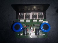
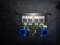
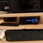
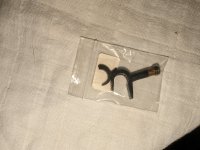
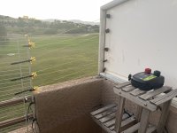
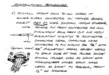
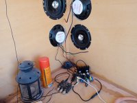
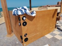
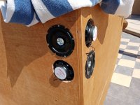
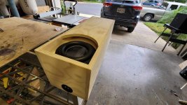
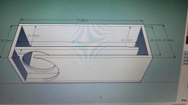
The thing looks like this:
20190213_153313_resized.jpg

By my standards, tidy enough that I am happy - but not a thing of beuaty and wonder.

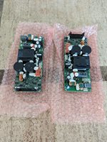
What is it? What is going on in that box?

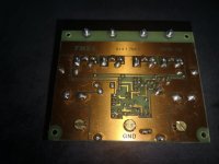
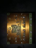
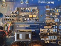
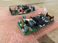
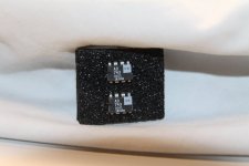
The heart of the thing is the PIC32MZ2048:
20190214_163533_resized.jpg

This is a generic PIC32MZ pcb that I use for all my projects. It comprises the PIC32, EEPROM, regs and headers for LCD and general I/O.

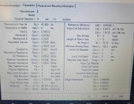
Running this 2 way crossover with 4th order slopes, and two parametric EQ's the memort is like 5%, RAM 7% and CPU load about 40% from what I see at 49,218ksps.

Huh? 49,218...

The reason for this is that this is an integer divisor of the 252MHz PIC clock, meaning the MCLK and LRCLK and BCLK are all nicely locked together without jitter.

In an embedded DSP, sticking to "normal" clock rates might look nice when you write the number down, but is actually meaningless. Unless you want to process digital data from external. Then I'd need to do a SRC... This clock rate works really nicely for the hardware...

The DSP has two "things" going on:
- The entire SPI read, DSP processing and SPI output occurs in an ISR that is triggered by the SPI buffer being half empty. Meaning this is rock steady on timing for keeping the SPI full for / from the ADC and DACS.
- The user interface is run when the ISR is not keeping things busy...

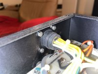
Other things in the box are the power supply and header breakout for the ADC and DACS...
20190214_163505_resized.jpg

Not a lot to say here, supplies power and stops cables getting too out of control. Again I sent this PCB off to the fab, as I tend to do a bunch of audio stuff from the PIC, eg my signal generator uses this, as does my PC based distortion meter.

The ADC plugs onto the power supply PCB. Samples data rns across the ribbon cable (every second wire earth) to the power supply board, then back to the PIC.

The PIc sends SPI / I2S to the DACS, two of them in this case, again via the power supply PCB.

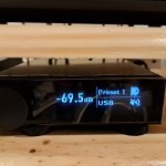
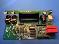
The user interface is on a 128 by 64 LCD, and is about as pretty as an engineer is likely to make it...


Volume control, with bar graph. In this case I am doing volume digitally. The tests I did against analogue volume chips showed that a CS4398 generates less distortion (if you can measure either of them). Its not that the analog chips are bad, but that the CS4398 is really good!

If you look on the right you might see the unloaded spot for the volume chips...

20190213_153327_resized.jpg

Save,Load config, Set up crossover, PArametrics.

20190213_153401_resized.jpg

20190213_153458_resized.jpg
Select crossover slopes etc.

And delay.

The parametric is similar, choose your CF, Q and gain and off you go.

Things I ponder adding are compressors, limiters and suchlike. These would be a complete doddle to add, as it really is just peak tracking and comparisons - but the audiophile in me always stops me at the last minute.

With about 60% processing spare, I could add an extra channel or two, or a bunch more parametrics.

All audio processing in this is:
- 24 bit SPI / I2S in and out
- Converted to 32 bit data
- With 64 bit accumulator for all DSP functions which is shifted back to 32 bit for storage

By doing all this in integer things really click along, so there is great lattitude for other things. I am pondering effects eg for guitar.

This is all coded in C32, microchips free compiler, which at times frustrates the hell out of me. I am not really a programmer so relearn every time I do these things, and their documentation is - lets say - complicated.

So whats it cost me?
- The PICS cost less than a burger
- The breakout board has more in value in LM317s than the PIC I suspect...
- The ADC and DAC are the expensive bits...
- CS4398's are probably US$10
- CS5381 are a touch expensive, I have lots of these as I was using them for my distortion meter. Perhaps a CS5361 at US$10ish would be more sensible - their performance is not far off the CS5381.

As you can see those boards are home made - the input and output op amps are either NE5532 or LM4562, which in this implementation I cannot tell the difference between even using fancy test gear.

All up this is probably $200 of stuff from my shelves, and a ton of time.

If you would like to play with this, or the code, feel free to drop a line and I can copy it to you.

By the way, the code is close on identical to the code that controls my ADAU DSP crossover, but the DSP ISR (plus SPI/I2S interface) replaces the external ADAU chip...
  • Like
Reactions: Vavilen
Projects by fanatics, for fanatics
Get answers and advice for everyone wanting to learn the art of audio.
Join the Community
507,915
Members
7,893,509
Messages

Filter

Forum Statistics

Threads
406,478
Messages
7,893,509
Members
507,915
Latest member
joenxxx24