Converting an old B&W 802F Series 1 to Active

I am the original owner of a B&W 802F Series 1 with the sealed woofers cabinet with the Fibrecrete heads. They are sitting there and I don't know what to do with them.

I am thinking of converting this into an active system using the MiniDSP Flex. I don't have high decibel needs and feel the 4 8" woofers can get me down to the last octave. My thought is that it would cost me more to create something similar than simply repurposing it. I have the amps necessary already.

https://www.minidsp.com/products/mi...Gvi4Gfh7ngP9pwaeiEi7jpIuTh-P-Qb4aAl9bEALw_wcB

Any ideas why this should not be done? Or why it might be a good idea.

Measuring Capacitance loading of Phono stage?

Hi,

I have a Shure V15 III catridge that works best at 400-500 pF capacitance loading.

The Preamp quotes 40pF loading, cables are supposedly around 100 pF and so logically I should add a 300 pF capacior, but I would prefer to measure if this is possible.

My DMM is not up to snuff, I have been recommended to buy an ESR, but I thought I would ask everone here what is normal practice in this case.

I was intending on leaving the preamplifier off, taking the leads off the cartridge and measuring from that point with the tunrtable plugged into the phn stage (valve)

Thoughts?

Repairing wood for flush driver mounting

Hi

I am currently restoring these speakers. Unfortunately, quite a bit of veneer has broken off underneath the drivers. What would be the best way to fix this in order to secure mounting without any leaks?
Planning to fill out the gaps with either wood filler or spray putty and sand as even as possible.
Then fastening the woofer ring with silicone and use gasket tape or some kind of caulk underneath the tweeter.

Other suggestions would be greatly appreciated. TIA! 🙂

PXL_20230809_095236693.jpg

I have a brand new sealed 12" SVS woofer out of a PB 1000 Pro. What should I do with it?

I contacted SVS to see if they can sell me an empty cabinet with the plate amp but they won't because I don't have a serial # to match a sale of the subwoofer. Pretty lame excuse but whatever. I own an office furniture company that builds custom cabinets so I have a million options. I have this external subwoofer amp: https://solen.ca/en/products/dayton-audio-sa1000-subwoofer-amplifier-rack-mountable.
I'm thinking of just recreating the SB 1000 with the same box dimensions. I'll just lose the "Pro" aspect of it because I won't be able to control it from my phone.

Any other suggestions? Does anybody know what the cutout should be for the 12" SVS driver? I've been told 11".

Thank for any help!

Bifurcated Horn like Cobreflex For 8" Woofer

Hi, Are there disadvantages to bifurcating a horn in a similar method to a University Cobreflex, though for an 8" woofer crossed at 100hz? Also, why not double this formula and incorporate two more horn channels in the vertical orientation also? The primary benefit I see is working with smaller bore channels allows for greater efficiency gains in a small volume of horn space. Any caveats or suggestions are appreciated. Here is a diagram of what I have in mind though incorporating a 6"-8" woofer rather than compression driver.
Reflex_horn_loudspeaker_drawing.svg.png

Vented Subwoofer Box with 1500 liters equipped with 2 pcs. Focal Audiom 15ax

on the attached pics you will see an example for a very stable cabinet (outer size in cm: 220x154x64) for 2x Focal "Audiom 15 ax" with a volume of approximately 1500 liter. Additional there are two diagrams with different kind of vented area (first long and small, second more close to square proportions as to see at the images (585x415 mm)
The enclosure was realized with beech multiplex (25 mm thickness and 11 layers).
Inside of the enclosure there was performed a closely braced. Due this step has been reached a negligible parasitic sound radiation at the cabinet walls.
I don't know commercial available subwoofers, where offers such a clean and tight bass transmission down to the lowest registers.

Attachments

  • DSC06080.jpg
    DSC06080.jpg
    716.4 KB · Views: 712
  • DSC06081.jpg
    DSC06081.jpg
    740.9 KB · Views: 642
  • DSC06082.jpg
    DSC06082.jpg
    810.6 KB · Views: 600
  • DSC06084.jpg
    DSC06084.jpg
    646.6 KB · Views: 590
  • DSC06078.jpg
    DSC06078.jpg
    749.6 KB · Views: 624
  • DSC06090.jpg
    DSC06090.jpg
    918.7 KB · Views: 479
  • DSC06077.jpg
    DSC06077.jpg
    768.1 KB · Views: 497
  • DSC06076.jpg
    DSC06076.jpg
    847.4 KB · Views: 518

DAB+ Portable Radio Panasonic RF-10DEB - the only DAB Receiver with published Service-Manual/Schematic ?

This brand don't use DAB modules from foreign manufacturers like Frontier Silicon etc. In use are obviously an own chip set.
On various German forum platforms this model is judged to be good in terms of reception characteristics.
From what other manufacturer of DAB/DAB+ stuff are such service manuals published ?
Thanks for an advice.

Attachments

BBQ Talk

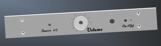
Let's discuss what everyone is running, or wishes they were running. And what you like or don't like.

I currently have two pits
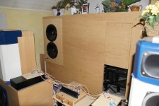
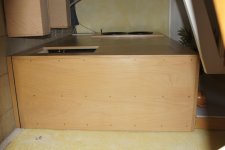
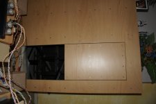
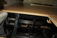
  • Traeger Timerline 1800
  • Texas Original Pits 55 gallon offset (Luling 20")
I've had a Kamado Joe Classic (Gen 1) in the past. Had to sell it when moving, as they tend to crack on long hauls.


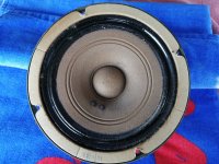
Traeger Timberline 1800

Pros
For quick cooks (grilling), or longer cooks (BBQ) that I don't have time to babysit, I use the Traeger. It works great on some foods, like salmon and chicken. It's excellent at holding low temps. It will cook reliably down to 165F, and really shines with smoked Salmon and jerky. It also does chicken very well. I think this is probably because it produces a drier heat than other types of cookers, which helps the skin to crisp more.

Cons
It's hard to get a good sear or get it to run consistently above 450F... despite what their marketing suggests. It also doesn't have the airflow that a offset can produce, so the quality of the smoke isn't quite as good. Finally, it is electric, so I have to cover the control panel when its raining out, which is a pain.

Would I do it again
I like the convenience of a pellet grill. But for the price that Traeger charges for the Timberline series, I'd probably look at a Yoder or a Mak instead.


Texas Original Pits Offset Smoker

When I want the best BBQ I can make and want to spend hours tending a fire, I use the offset. It's configured as a Texas-Style direct flow (top down cooker) pit. It makes fantastic ribs and brisket. It's also great if you have a friend that also like to BBQ, and you want an excuse to sit around for 12 hours burning a fire and drinking beer.

Pros
A direct flow offset arguably produces the best BBQ you can make. The top down cooking nature of this style allows the fat to render on the top without burning the bottom. And the draft these cookers can produce allows them to run a little hotter than other cookers. They also produce a very high quality smoke. Finally, running a stick burner has a primal appeal that's hard to replicate with other cookers.

Cons
A good pit will be physically much larger than other styles of cookers. You also want one that's made with 1/4" tick steel, which will make it very heavy... think 400+ pounds at a minimum. A good pit will be expensive and a cheap one will need to be extensively modified. Finally, these pits need constant attention. You'll be feeding or tending the fire every 15 minutes for hours on end. Note for everyone.

Would I do it again
The Texas Original Pit wouldn't be my first choice. The stack is too small and short, and exit point it too high - which is difficult to modify. For the same price that these run new, there are better options. However, good pits can be very expensive, and I found this one locally at a fraction of it's retail price. If I was to buy a new offset and money wasn't an option, I'd lean toward Smoke Norths pits or maybe Fat Stacks.

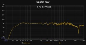
I have an older model of the Luling. To get it to run properly, I had to modify it as follows:
  • Semi-insulated firebox using 3/4" firebrick
  • Stack extension to increase draw
  • Two grate-level TelTru thermometers
  • Water pan (1/4 size food pan)
  • No baffle plates, other than a small 2" lip at the firebox opening that helps to create a swirl in the air flow.
The placement of the waterpan took some trial and error to get right and likely had the biggest impact on getting it to run well. I run it under the grate at the firebox throat. In this position, it helped immensely to even out temps across the cook chamber. I run with 5 degrees end-to-end. I think this is because the Texas Original Pits have a very large opening. Much bigger than a Franklin Pit or Smoke North Pit. I think partially blocking this with the water pan helps to control the airflow and force the draft upward.


Kamado Joe Classic

I'd don't actually own this anymore, but will still give my thoughts

Pros
Very versatile, and simpler to run than an offset. These can run from 200F to well over 700F. Great for slow and low BBQ and also wonderful for direct heat grilling. They can run hot enough to run a pizza stone - Something the Traeger struggles with.

Cons
It takes about an hour or so to get running, which can be tough for quick weeknight cooks. They hold temp well, but do still need occasional tweaks. Which makes it a bit tricky to cook with if you're doing an overnight cook - Like a pork shoulder or brisket that you want to serve at noon. They're best to buy new as the ceramics will crack with use and time - the warranty is very useful in this regard.

Would I do it again
I'd love to get another Ceramic Cooker - whenever I can get spousal approval. I like the Kamado Joe, Big Green Egg and Primo cookers. I lean toward a BGE, as my local retailer has a large stock and can handle warranty claims. But I like the made in the USA nature of the Primo.

So... what's everyone else running?

Interest in PCBs for Omicron headphone amplifier

This group buy is now closed. All Omicron boards have been manufactured, assembled and tested (if requested) and shipped to participants.

If you want to be notified of future events concerning the Omicron headphone amplifier, drop me a PM.

Also, be sure to read through the main Omicron discussion thread - it is relatively short at 11 pages but is choke full of information.

Programming SigmaDSP chips (e.g. ADAU1701) using USB on STM32 microcontroller

I am designing a class D amplifier that will utilize the ADAU1701 DSP. On the same board there will also be STM32 MCU that has USB capabilities. The USB will be used for audio class and firmware updates but since the MCU also has several I2C and SPI buses it would be very nice if it could directly support programming of the ADAU1701 from Sigma Studio.

This would allow the user to connect the amp board directly to the PC where Sigma Studio is running and there will be no need to use external USBi programmer (such as the CY7C68013A based tools).

The question is: has anyone tried to implement this? I am a bit clueless where to start. Would that be even possible or is the external programmer the only option?

3.1 A/V question

Hello everyone, I purchased this 5.1 decoder off ebay and I’m having difficulties getting it off the ground. It has dismal pre out voltage and my tv remote switches functions on it haphazardly. I’ve bought some cool little signal amplifier boards but I’m on the fence about dealing with the remote thing. It seems to break down the surround information into discrete channels which is cool but the remote glitching is diminishing the spousal acceptance factor.

https://www.ebay.com/itm/3254510898...UcG3IQTTzC&var=&widget_ver=artemis&media=COPY

If I can live without the rear surround channels is it almost the same to sum the L&R channels to mono for the center and subwoofer then just run the L&R signal for the front mains? I can input stereo analog instead of optical into the 5.1 board but the pre out voltage is still a problem. I understand that it just creates a faux surround sound from a stereo analog input so I’m not interested in dealing with the thing if I’m not getting actual 5.1.

I’m using the Dayton Audio Kabd boards in the receiver I built.

I suspect that it may require doing the L-R L+R thing which I don’t feel like doing. This is my stereo as well as tv sound and I don’t want to play with the mains music delivery.

Onkyo 805 internal amps vs. Quad 405

I picked up some brand new Elipson Legacy 3210’s a little while ago for my small secondary 2.1 setup. Right now I’m powering it with my Onkyo 805 which is highly regarded for its amp portion. Would a Quad 405 power amp be an upgrade? I have one sitting downstairs and I’m curious before ripping stuff apart for an AB comparison.

If the 405 is considerably better are there any upgrades/updates I can do as a very inexperienced DIYer with amps?

Please help modify this circuit (uncomplicated)

Hi,

I have a 4th-order high-pass filter crossover module. I'd like to use it only as a 2nd-order high-pass filter.

Please help me how can I rewire it to achieve the goal?

Attachments

  • 4th.png
    4th.png
    128.1 KB · Views: 122
  • 2nd.jpg
    2nd.jpg
    63.3 KB · Views: 116
  • 366544847_23898206493098045_5693973058706109144_n.jpg
    366544847_23898206493098045_5693973058706109144_n.jpg
    62.5 KB · Views: 105
  • Installation notes_MX Modules.pdf
    Installation notes_MX Modules.pdf
    3.8 MB · Views: 118

Musical Fidelity B1 doubts

Hi,

I'm restoring an old Musical Fidelity B1 amp. I've found some pics and schematics in the web, but it seems that my model is quite different: apparently it seems to be a very first version, or even a pre-series unit (serial # 00049)

Especially, I have not found any pot able to adjust the bias current (see pictures). Moreover, R40 and R46 resistors have never been mounted. The only adjusting point is a 2K trimmer mounted at R30 place on right channel only , I suppose to allow a preset balance between the two channels.

No way to balance the DC output and to adjust the bias?

Many thanks in advance, Paolo

Attachments

  • Musical Fidelity B1 b.jpg
    Musical Fidelity B1 b.jpg
    680.3 KB · Views: 243
  • Musical Fidelity B1 c.jpg
    Musical Fidelity B1 c.jpg
    606 KB · Views: 225

Help with 18 inch Sub Enclouser vented (2)design

Hello Friends,
I have 2 18 inches sub driver and wants to design for them. I have the parameters and tried my best to design on a software but was unsuccessful.
If anybody can please give me a design dimensions I’ll be grateful.
Driver 18 inch 1500 W 4.5 inch in out coil. Pure paper cone.
NOMINAL DIAMETER: 18 inch / 457 mm
RATED IMPEDANCE: 8 ohms
PROGRAM POWER: 3600 W
POWER HANDLING CAPACITY: 1800 W
SENSITIVITY: 97.0 dB
FREQUENCY RANGE: 30 – 1000 Hz
EFFECTIVE PISTON DIAMETER: 395 mm / 15.55 inch
MAX. EXCURSION BEFORE DAMAGE: 54 mm / 2.13 inch
MINIMIM IMPEDANCE: 6.8 ohm
VOICE COIL DIAMETER: 4.5 inch / 114 mm
VOICE COIL WINDING MATERIAL: Copper
VOICE COIL LENGTH: 34 mm / 1.34 inch
NUMBER OF LAYERS: 2


Thiele - small parameters
RESONANCE FREQUENCY (FS)30 Hz
DC RESISTANCE (RE)5.40 ohm
MECHANICAL FACTOR6.70 Qms
ELECTRICAL FACTOR (QES)0.29 Qes
TOTAL FACTOR0.28 Qts
BL FACTOR (BL)30.50 T x m
EFFECTIVE MOVING MASS (MMS)260.0 g
EQUIVALENT CAS AIR LOADED (VAS)220.0 liters
EFFECTIVE PISTON AREA (SD)0.120 m2
MAX. LINEAR EXCURSION (XMAX)14.0 mm
VOICE COIL INDUCTANCE @ 1KHZ (LE1K)1.38 mH
HALF-SPACE EFFICIENCY (EFF)1.90%
Mounting Information
OVERALL DIAMETER465 mm / 18.31 inches
BOLT CIRCLE DIAMETER442-447 mm / 17.4-17.6 inch
BOLT HOLE DIAMETER7 mm / 0.28 inch
FRONT MOUNT BAFFLE CUT-OUT424 mm / 16.69 inch
REAR MOUNT BAFFLE CUT-OUT 424 mm / 16.69 inch
VOLUME OCCUPIED BY THE DRIVER6.5 liters / 0.26 ft3
CE MARKINGYes
SIZE
WEIGHT15.2 kg / 33.51 lbs
HEIGHT212 mm / 8.35 inches
DIAMETER465 mm / 18.31 inches

Need help with adjusting a Kenwood TK-140X

Hi all,
I've just finished a repair and overhaul of a Kenwood TK-140X. Finally, I would like to turn the potentiometers a bit to really have done everything. However, I only have a circuit diagram of the device and unfortunately cannot find any adjustment instructions for the preamplifier (which is unusual anyway) or for the power amplifier.
Has anyone ever compared this device and/or documents on it, or can anyone help me in any other way?
Thanks in advance for reading and any help

Leak 3007 cassette tape player - manual

Would anyone know where I can source a service manual for a Leak model 3007 cassette tape player.

I dragged this out of storage so I can go through and digitise my collection of old tapes, but it has frequency response and level problems on one channel. I cannot find a service manual online and suspect it will be difficult because the unit was purchased in the 1970s.

I would be really grateful if anyone can point me in right direction.

Many thanks,

Purifi EVAL1 Ghent case build instruction

Hi, this is my first post on this forum. I have however been here many times reading a lot about how to build my nCore mono amplifiers a few years back and also on how to build a stereo Purifi EVAL1 amplifier very recently.

However, I was not able to find a clear step-by-step instruction on how to build a stereo Purifi EVAL1 amp. So I created an instruction myself. I figured it would be nice to share it here as many like me would try to find such an instruction here.

I used the Ghent Audio stereo Purifi case kit, Ghent Audio harness, Hypex SMPS1200A400 and the Purifi EVAL1 module.

Hopefully you like my step-by-step guide. If you have suggestions or find errors, please let me know. Thanks!

Link: iCloud

BR,
Richard

I cut my speaker in half & I need help restoring the sound

Hello, I cut a bookshelf speakers depth in half then doweled and glued the two parts back together. I’d like to get it back to its original quality (it’s a Sony SS-CS5). Can I just add more damping material to the interior or am I going to need to make a box that is the same internal volume? I can just make a new box on a cnc, but to keep that volume and depth of 4” (total) it would need to be almost double the length it currently is. I’ll attach the dimensions of the original, what I made, and if I kept the same volume and depth.

I’m thinking if I need to make a new box I could make it out of 3/4” maple plywood instead of the 1/2” mdf, if that would make a good difference.

Also, is there any way I can find specifications on the speaker drivers themselves?

Thanks.

Attachments

  • SS-S5 Orig Box.png
    SS-S5 Orig Box.png
    126.4 KB · Views: 93
  • SS-S5 Halved Box.png
    SS-S5 Halved Box.png
    107.4 KB · Views: 88
  • SS-S5 Prosp Box.png
    SS-S5 Prosp Box.png
    48.8 KB · Views: 94

PA system

Hi, I know very little about PA systems, I run a small choir with 4 concerts a year, two of which are outside. We have an existing PA system that work very well. Subzero 815, 8 channels,300w peak rated 200w 100w x2 The speakers are passive 100w RMS 15 woofer 45--20K. my question is we want to add two more speaker to the kit. It is not to increase the volume but to allow drection when outside. Can I do this whit my system and if so what speakers should I add? Please be non tech. Thanks

Using 2 subwoofers with different characteristics to improve overall performance?

This is a wild idea, far away from an implementation plan. I am just wondering if the idea is worth pursuing.

I love transmission line enclosures. But they have disadvantages like a dip at the 5th harmonic. Other minima can be mitigated with damping material. But more damping material has an adverse effect on the lower frequency range.

Currently I am using a large transmission line in my home cinema. The room is small (5x4 meters) and I have quite an uneven bass experience at different locations in the room.

In ancient times, we used to build stereo speaker systems which were left and right as equal as possible. If I recall, there were problems with bass amplification due to room resonances. But I don; t recall bass cancellations effects as bad as I have now with single sub woofers.

So I was thinking. What if I split up the current huge transmission line into 2 separate lines with about the same but unequal channel length, and half the channel area. Use 2 smaller drivers with a smaller area. So the channel area / driver area ratio would remain the same as recommended per design rules. The total volume of both sub woofers would be roughly equal to the volume of the single sub I have now.

Then, make the design of the transmission line length different for each of the drivers, so dips and peaks do not coincide. In addition, each sub would be placed at a different side of the room.

I assume this would lead to a more even bass reproduction throughout the room because of the different locations of the speakers. And a more even frequency response because the two transmission lines.

Or is this just a nonsense idea and should I better build 2 equal sub woofers and drive them as part of a stereo system using left/right amplifiers. Instead of combining both bass channels in a single sub channel?

Best way to bypass tone controls on Fosi Audio TB10D (TPA3255)

Greetings. I have a Fosi Audio TB10D on order. I secured it for a good price but I want to have the option of bypassing the tone controls.

It seems to me I could replace one of the tone control potentiometer to add one with a built in switch, then use something like this audio relay to bypass the tone controls.

Any thoughts?

Aliexpress - Ultra-small Double Pole Double Throw Polarity Relay Module Mini

On reflection, what might be better is to use the switch on the potentiometer as the power switch, and the existing power toggle to enable the tone defeat...

Single Bass Array from in wall 3-way speaker

Hey people!

As I do some changes in my listening room I try to perform some measurements - probably interesting for someone.
This is a listening room for mixing/mastering after non environment principle which also works as my measurement room with some additional mobile absorbers. For my test listenings with KH120ii I changed the usual layout and added additional absorption.

My main speakers have their low frequency drivers close to the points where they need to be for a single bass array. And I wanted to show you that this works and is a fairly easy way to have better low frequency performance.
Here is the setup:

Measurement setup - pic.jpg


I did 6 different microphone positions but all on about the same plane 10-20cm after the little table, varying up/down and left/right position (the directions a BSA should work). Cause of the not perfect positioned LF drivers I expect them to work as array till 70-80Hz.

Here is the variation from the KH120ii lf driver at mic positions:
KH 6 pos.PNG

That's actually not bad - my room is extremely well dampened. Measurement is a sweep of 2s, no windowing at all. But at 100Hz it's about +-8dB and at 70Hz +-4dB. No room measurement system of the world can do anything against that.

And that's the array:
REF 6 pos.png

I got a lot more low frequency content - that's the glory of closed speakers tuned to the room. At 70Hz I have about +-1,5dB and at 100Hz (where the array is not working any more) I'm still better with +-6dB (but most curves are pretty close, only 2 extreme mic positions are far from them).

For a more scientific view I would have to compensate the distance of the mic and absolute level and take better care about these microphone positions - but I hope it's clear that it has a positive effect and with thoughtfull positioning of your lf drivers you can chancel a few room resonances - for "free".

(p.s.: this only works when the music/film content is mono at low frequencies! Which it mostly is)
  • Thank You
  • Like
Reactions: AllenB and GM

Luxman L100 pointers needed

Hi.
I am working on a Luxman L100, which has weird behavior. It sometimes works, other times one or both channels will output some 40v to 50v DC without the protection kicking in. I think it is a gnd issue, but haven't seen any bad wires, traces or solder joints. When it works, the sound is good, idle current and DC offset is within spec. It will sometimes work for half a day at a time. Temperature does not seem to influence it much, as the weird behavior sometimes appears from cold start.
Other times it will play a while before the error occurs.

I would be happy if someone could give some pointers on where to look first, as this amp isn't exactly the most fun to poke around in.

/Jørgen

help needed locating power transformers of Esoteric P70 transport

Dear, all.
I am posting on behalf of a dear friend of mine.

I used 9 years a Teac Esoteric P-70 CD-Transport as my system source and got a superb quality out of it.

Lately I made a mistake and burnt its 2 power transformers by input of 230 Vac instead of 110 Vac.

The 2 transformer primary sections burnt.

Now, I am looking to replace those 2 transformers.

The Teac service Center in USA, Germany and Japan said that it is obsolete (do not have it any more).

They appears at page 7 it ems 2-23 and 2-24 of the device Service Manual):

1. E00561920A power transformer, RCOA A (US, C)

2. E00561820A power transformer, RCOA D (US, C)

I disassembled them from the device and found on them the following:

Both of them are 30VA R-core transformers made by KITAMURA KIDEN CO. Japan

1. E005618-20A KRT-15-P-007S3 K2X3SK TT2KY1

2. E005619-20A KRT-10-P-007S1 K2X3SK TT2KY1

I also tried to find a live e-mail to contact KITAMURA KIDEN Co. to order those transformers with no success.

Please anyone, Please help me find those

(new, second hand or just a live contact to KITAMURA KIDEN Co.).

Thanks in advance

SMD Emitter Resistors Anyone?

Hi,
Anyone tried using SMD for Emitter resistors?
I found this on Mouser (https://www.mouser.sg/datasheet/2/303/RWS710_1_12_41-768831.pdf). Footprint is not that small, but the derating specs looks better than most THT and the ppm/C not bad either. Price is decent too.
I’m planning to build an Elliott P3 amplifier so it’s approx 60W and I never need anything bigger honestly. I know many advocate Mills MRA for their non-inductive properties, but they are expensive and selection is limited (at least where I am)
Cheers everyone and stay cool in this hot summer.

help with bass reflex port response

Hello to everyone, it is been a while since i last postet on this forum. I recently build new speaker cabinet for my seas excel drivers. I just need your opinion on the port frequency responce. I use the W26fx001 woofer in 60l cabinet with 70mm diameter and 260mm port lenght (front port). The port measurement shows that the port is working just fine in the low end but there is something at 200-500 hz. It doesn't affecting the overall speaker responce but what is that? port resonances? The woofer near responce dont show significant cabinet resonances. Or just the port noise due to the air blowing at the mic? You can see the port responce with the crossover filter aplied also. the cross frequency is at 400Hz LR24db and at 1600Hz LR24db. The other speakers are the W15ch001 and the T29cf002 tweeter. The speakers is active with electronic crossover using IIR for the filters and EQ and FIR for the LR filter linearization. And of course delays are also applied on the mid and tweeter. The speaker sounds great but just wanna know where the port energy at 200-500Hz is coming from.(can't sleep at nights 🙂 )

Attachments

  • port near.jpg
    port near.jpg
    72.5 KB · Views: 190
  • port near with filter+eq.jpg
    port near with filter+eq.jpg
    65.1 KB · Views: 181
  • woofer near.jpg
    woofer near.jpg
    67 KB · Views: 158
  • total fr.response.jpg
    total fr.response.jpg
    64.9 KB · Views: 148
  • total reversed.jpg
    total reversed.jpg
    66.9 KB · Views: 141
  • total step response.jpg
    total step response.jpg
    53.5 KB · Views: 140
  • total impulse response.jpg
    total impulse response.jpg
    55.5 KB · Views: 172

DIY Voice Coil Winding Machine

CNC Winding Machine

Facebook group: Arduino CNC Winding Machine
Arduino Project Hub:
CNC Arduino Winding Machine

1659691418153.png

1659691436998.png


*Updated Codes download below updated 5th August 2022
  1. Winding Machine GUI v0.3.4 Beta.zip - Visual Basic Source Code(Required Microsoft Visual Studio)
  2. Winding Machine GUI v0.3.4 Beta.exe - Winding Machine GUI exe file
  3. Winder_Shield_v0.3.1.8.zip - Arduino Firmware
  4. Wiring Diagram(Due) v0.3.zip - Arduino Due Wiring Diagram in Microsoft Visio
Login to view embedded media Login to view embedded media Login to view embedded media Login to view embedded media Login to view embedded media

Attachments

  • Control Buttons.png
    Control Buttons.png
    15.7 KB · Views: 584
  • E-Stop.png
    E-Stop.png
    13.1 KB · Views: 539
  • Limit Switch.png
    Limit Switch.png
    27.4 KB · Views: 553
  • Logic Leveler.png
    Logic Leveler.png
    26.8 KB · Views: 528
  • Speed Pot.png
    Speed Pot.png
    13.5 KB · Views: 546
  • Stepper Motor Controller.png
    Stepper Motor Controller.png
    81.2 KB · Views: 553
  • Toggle Switch.png
    Toggle Switch.png
    12.9 KB · Views: 560
  • SD Card Connection.png
    SD Card Connection.png
    44.6 KB · Views: 564

Memphis 16-MCD1500 repair help

First post.. thanks in advance for any help.

I have a Memphis mcd1500 that had blown up or at least had some bad Ird3205.. I sourced them Nos from out of country .. and replaced all of them and all the ird 640 also the irf 9640 .. the amplifier will power on now no protection light comes on but it isnt receiving a drive signal from the board... I believe it to be the chips are blown but Memphis has sanded off the part numbers .. or if any of y'all could think up something different it may be let me know .. I'd appreciate it ..

I removed all the amp section MOSFETs and rechecked but I have no drive signal ..

Any idea what the part numbers are in the ic chips??

Attachments

  • PXL_20230626_062200341.jpg
    PXL_20230626_062200341.jpg
    591.5 KB · Views: 179
  • PXL_20230626_062215268.jpg
    PXL_20230626_062215268.jpg
    538.8 KB · Views: 159
  • PXL_20230626_062234247.jpg
    PXL_20230626_062234247.jpg
    673.1 KB · Views: 159
  • PXL_20230626_062236304.jpg
    PXL_20230626_062236304.jpg
    809.1 KB · Views: 186
  • PXL_20230626_062238415.jpg
    PXL_20230626_062238415.jpg
    661.4 KB · Views: 181

Monolith THX satalite CBT

Hi all,

I don't know that much about the limitations of CBT line arrays, but can a bunch of small 4.5 inch coax drivers be effectively used in a line array or CBT with 4m listening distance?

I know these measure very well:
https://www.soundandvision.com/content/monolith-m518ht-51-thx-subsatellite-system-review

Erin is about to release a spinorama on them that looks promising apart from SPL limitations/distortion.

80db/1w each, but they are very cheap.

What do you think?

Hello

I'm new here, I was cleaning up some stuff and came across a Leach low tim amplifier I started building more than 10 years ago. I purchased all the components , etched and partially populated the boards, then kind of got stuck at matching transistors and diodes. I would like to finish the amp but its seems beyond my current skills and tools I have. I am here lurking and reading for the most part.

Contributors to BASS

Gents, I've been working with various sets of speakers for some time now, improving components, wire, adjusting things as I go. What you you say would be the primary contributors of gaining more bass out of any given set of speakers? For instance, does the amount of dampening material - less or more contribute? Value of capacitance / mH, longer tube, shorter, etc? Driver? If tackling a pair of speakers, where would you zone in first?

Alchemist Kraken APD8A MKII

Hello all, I just stumbled into 2 nice examples of these in working condition. Not pristine, but no damage, and a cleanup will do them nice. While trying to figure out what they were I ran into some people that mentioned upgrading resistors and replacing caps. I was wondering if anyone here has messed with them and had any advice, or just wanted to take a look at the design and recommend some upgrades. I am interested in upgrading one and being able to compare it to the other. I am amateur DIY guy, can read values, unsolder and resolder well enough. I would only be looking for info on what to pluck out and replace/upgrade. Looks like it could be fun. I also always ask before I get into something like this, is there any lethal voltage I could encounter in the amp itself, not the power supply? Any thoughts folks? Here are a couple links that might inspire you to look around.

Edit, I think these are late model 1?

https://alchemisthifi.info/ranges/kraken/alchemist_kraken_apd8_power_amplifier.htm

https://www.audiog.com/en/item.aspx?item=2442

https://www.darkhorseaudio.co.uk/portfolio/alchemist (this is an upgrade of the integrated amp tht looks to have a similar build)

http://www.audioreview.com/product/amplification/amplifiers/alchemist/kraken-apd8a.html (a couple reviews mention some upgrade ideas)

High Gain Tube Preamp PCB, power supply on or off-board?

Hi all,

I got the bug to make another guitar distortion making device around the same time I realized I never bought a 5150 when I was a teenager. Below is a screen shot of a PCB layout that is 80% done for a 5150 preamp. I have a Toroidal Transformer collecting dust that seems well suited and I'm weighing options for where to put the B+ rectification and filtering. As you can see my first inclination was to put it in the left side of the PCB but I'm wavering and considering a second board because I'm concerned about rectifier noise and proximity.

It may not be clear but I'm following a ground bus approach with the most sensitive signals on the far right. The first two filtering stages are separated by a balanced filter per Merlin's Grounding Chapter to dissuade rectifier currents from polluting audio. I'll be tying the PCB ground bus to earth at the input end as well.

I also need to cram in a regulated DC rail for the heaters and possibly a low voltage solid state buffer on the output. That alone may push me into a separate supply board but I could also stick a 3rd party module in there I guess.

For those who have packed their AC-DC section onto the same board as signal what methods did you use to avoid noise pollution?

Attachments

  • Like
Reactions: exlabs

Chip Amp before another amp for noise reduction?

Update 1: The high pass is not for noise, it's for the ported full range speaker.
Update 2: As @diyMartin points out, the NE5532 won't drive a speaker. I put it as a placeholder but it's misleading.
Update 3: Also thanks for pointing out that the neg output of the TDA7297 cannot be grounded as I did in the sketch.

Hello there.

I have been trying class A/B amps and a tone preamp.

I took the noise out of the TDA7850 with a capacitance multiplier.
1690792674227.png


I ran the preamp with a battery after replacing the ICs with ones I know are original, still have to check the ones I got with it.
1690792716390.png


Both work now if the source is a phone. But... They don't like a desktop computer or laptop with a charger.

.....

The TDA7297, connected to a switching power supply, and to the desktop computer, doesn't care. Zero hum. I love how it sounds, I only use a few watts. A TPA3116d2 I have doesn't produce hum either in this setup.

1690793387433.png


I recently got a toroidal transformer with auxiliary outputs, so I could run a TDA7297 and another amp without sharing the same transformer output lines. So, two questions:

1) If I use separated outputs from the toroidal transformer, can I run an amp after a TDA7297 board like the one I have above with little gain so that I can reject line noise? The ground is still shared... The NE5532 is a placeholder, I would put another amp with some gain.

2) Is a 60Hz high pass like this one OK here? assuming the amp to feed has input impedance > 10k Ohm.

I power a pair of 8ohm full range speaker and I don't use more than a few watts. This is the idea, not an exact schematic...

1690793581502-png.1198142


I got a scope and I hope it help me debug issues... Not there yet, learning. BTW, the house electricity is not good, it's 130V and it doesn't have ground, online L and N.

Attachments

  • 1690793502585.png
    1690793502585.png
    113.1 KB · Views: 112
  • 1690793581502.png
    1690793581502.png
    22.5 KB · Views: 444

Modular Preamp / Heaphone Amp Chassis ? (move to another section if more appropriate)

Creation of the UMS specs for heat sink in addition the 10mm*10mm hole pattern add-on plate on Hifi2000/Modushop chassis is great for flexibility in an amp / power amp.
Yet, having build one amp+preamp into 1 chassis, I am on the path of building more and slowly wishing there would be a standardization on preamp/headphones amp boxes
But instead of UMS specs for transistors placement, there would be UMS specs for:
  1. front panel: power switch, led, Alps volume control, source switch : always standards position
  2. back panel: power inlet, RCA inputs, RCA outputs : always standards...
There is already a nice case from Hifi2000/Modushop for the B1 Kong preamp, just lacking the hole for the headphone jack. The shop was nice to send me the 2D of the front panel so I could adapt to another front panel (4U to put the Korg preamp into a big “power amp” box), so there is the base for a “UMS specs for preamp/headphone amp”

Something that would be “made for ACP+ preamp” & adaptable for other like Noir, Korg, Pete Millet Nutube board and so on.
Reasoning
  1. ACP+ doesn’t have a well made chassis like ACA. Having one would make it nicer and could be integrated in style with the current ACA chassis
  2. ACP+ has RCA binding post fixed on the PCB board whereas others don t, = if backpanel tolerances OK for ACP+, "free" RCA should be easy to install.
  3. ACP+ board is the biggest compared to others (from what I gathered) so, if it’s fits inside, everything would.

To do
  1. I have not checked yet if an ACP+ board fits a standard chassis given the depth of the board with welded components back and front and standard Galaxy chassis dimensions
  2. Also to be done: checking the height of the ACP+ and others to see if 1U is ok or more height is required…
  3. Every component of ACP+ being welded on the PCB lead to lots of constraints... to be checked/compared with others boards.

Precise dimensions of the ACP board are needed, they could be reverse-engineer from Nelson article, but would do that only if people would think the idea has merits and there could be a connection with the DIY Audio store and/or Hifi2000/Modushop…Also, I don t have an ACP+ myself, so there could be a few mm of misses…Ok to throw ideas around, not for manufacturing a real product...


So do you think this is something (the overall idea/direction) that could be interesting for some?

Attachments

  • Concept.jpg
    Concept.jpg
    502.2 KB · Views: 105
  • Concept-Box.png
    Concept-Box.png
    6.1 KB · Views: 109
  • Front-Plate-rear_view.png
    Front-Plate-rear_view.png
    10.5 KB · Views: 108
  • Front-Plate-front_view.png
    Front-Plate-front_view.png
    14.3 KB · Views: 97
  • BackPlate-with-lots-of-leeways.png
    BackPlate-with-lots-of-leeways.png
    12.1 KB · Views: 106
  • ACPplus-in-300mm-MiniDissipante-check200mm.png
    ACPplus-in-300mm-MiniDissipante-check200mm.png
    48.2 KB · Views: 113

Compact subwoofer box for Peerless SLS-P830946

Hello everyone,
I've been trying to design for the first time an enclosure for a subwoofer with a Peerless SLS-P830946 sw. I came up with a 12 L box (final shape not considered yet), with a port tuned for 30 Hz. Made some calculations on WinISD and the result is a slot port of 30 cm2 cross area, 3 x 10 cm, about 78,6 cm long. I attached some graphs of spl, max spl and port air velocity. the slot port would be folded in the inside of the enclosure.
The whole project is for a car subwoofer that has acceptable extension and loudness and does not take too much space in the small trunk of my car.
Anybody can tell me if I should revisit something in the project or if there are better ways to achieve my goal?
Thanks in advance!

Attachments

  • Max SPL.png
    Max SPL.png
    69.5 KB · Views: 105
  • Port air velocity.png
    Port air velocity.png
    59.4 KB · Views: 93
  • SPL.png
    SPL.png
    68.6 KB · Views: 95
  • Transfer function magnitude.png
    Transfer function magnitude.png
    69.4 KB · Views: 99

Which characteristics are more influent on the sound of SET amps?

Hi,

the title has been chosen to explicit that this is a pour-parler kind of thread, to better understand the preferences many people have on the SET amps.

I would like indeed to ask your opinion on which characteristics make SET amps so special compared to other kind of amps.
Is the predominance of 2nd (and then 3rd) harmonic distortion?
Is the absence of gnfb and so a different saturation behaviour and recovery after peaks?
Is the relatively low DF, generally between 2 and 4, and the consequent interaction with the speaker (more low-highs, even if less controlled)?
Others?

Thanks in advance.

J270 fets NOS build your own Beast of a 1000 fets!

Would anyone have any interest in some NOS J270 fets??? I used to work for Audio Research corp and I have about 10,000 of these i horded when we cleaned out the warehouse one year. I boiught a bunch of parts from the company and it's time to start letting go of them. Build your own Beast of a 1000 Jfets!!!
these are currently about $4each at Mouser, $2each in 1000 piece quantites. I am open to offers. looking to sell them in large lots if not ALL in one shot. preferably.
PM me for details.


ZC

20230724_094745.jpg
20230724_094754.jpg

Attachments

  • 20230724_094800.jpg
    20230724_094800.jpg
    529.7 KB · Views: 90
  • 20230724_094851.jpg
    20230724_094851.jpg
    389.6 KB · Views: 97

Hafler Output Mosfets

Found this container of Hafler Mosfets in my stash. these were part of my ARC Cleanout 10+ years ago. they all appear to be QN112's except for 2 are the 176's it appears some have been tested/graded??

$50 for the lot shipped in the USA

Attachments

  • 20230729_121306.jpg
    20230729_121306.jpg
    316.1 KB · Views: 175
  • 20230729_121309.jpg
    20230729_121309.jpg
    497.5 KB · Views: 196
  • 20230729_121438.jpg
    20230729_121438.jpg
    492.6 KB · Views: 209

Air Dielectric Variables Capacitors -- NH USA -- pots -- Ohmite resistor

Best offer

Attachments

  • 20210903_163520.jpg
    20210903_163520.jpg
    1 MB · Views: 278
  • 20210903_163548.jpg
    20210903_163548.jpg
    1,002.4 KB · Views: 259
  • 20210903_163659.jpg
    20210903_163659.jpg
    1,016.7 KB · Views: 246
  • 20210903_163719.jpg
    20210903_163719.jpg
    1 MB · Views: 228
  • 20210903_163727.jpg
    20210903_163727.jpg
    1,007.1 KB · Views: 234
  • 20210903_163733.jpg
    20210903_163733.jpg
    1,001.4 KB · Views: 211
  • 20210903_143342.jpg
    20210903_143342.jpg
    747 KB · Views: 211
  • 20210903_164114.jpg
    20210903_164114.jpg
    928.8 KB · Views: 209
  • 20210903_163805.jpg
    20210903_163805.jpg
    978.7 KB · Views: 186
  • 20210903_163816.jpg
    20210903_163816.jpg
    980.6 KB · Views: 222

Western Electric Altec 755A woofers drivers Acoustic Research AR-1 speakers alnico full range -- NH USA

$4000

Work perfectly.

WESTERN ELECTRIC ALTEC 755A woofers drivers Acoustic Research AR-1 SPEAKERS alnico full range

Attachments

  • IMG_20200124_125824.jpg
    IMG_20200124_125824.jpg
    736.3 KB · Views: 252
  • IMG_20200124_125833.jpg
    IMG_20200124_125833.jpg
    810.5 KB · Views: 205
  • IMG_20200124_123107.jpg
    IMG_20200124_123107.jpg
    697.6 KB · Views: 181
  • IMG_20200124_123109.jpg
    IMG_20200124_123109.jpg
    696.3 KB · Views: 207
  • IMG_20200124_123445.jpg
    IMG_20200124_123445.jpg
    364.7 KB · Views: 184
  • IMG_20200124_123455.jpg
    IMG_20200124_123455.jpg
    366.1 KB · Views: 209
  • IMG_20200124_125244.jpg
    IMG_20200124_125244.jpg
    661.8 KB · Views: 176
  • IMG_20200124_125259.jpg
    IMG_20200124_125259.jpg
    853.4 KB · Views: 190
  • IMG_20200124_125328.jpg
    IMG_20200124_125328.jpg
    453.3 KB · Views: 211
  • IMG_20200124_125335.jpg
    IMG_20200124_125335.jpg
    473.6 KB · Views: 168

For Sale 17x GRS PT6816-8

I want to sell 17x GRS PT6816-8.

I want €500 for all of them, the buyer pays the shipping fee.

The drivers are currently in Stockholm, Sweden. Local pickup would of course be preferable.

They have only been used during testing of the drivers and speaker designs. My reason for selling is that I want to build a physically curved CBT and the driver is too tall to work well in that application. They shine, however, in a straight array.

All drivers are in their original cardboard boxes as received from Parts Express. I also have the original outer shipping box with packing from PE.


Consistency across all drivers is great as can be seen in my measurements of them:

Distortion: https://drive.google.com/file/d/1Pnbsi0WBYmTebrhg_wYINsAWpoJWUaO9/view?usp=sharing (ignore frequency response, they were measured at close distance in a vice with the goal of consistent measurement conditions across all drivers, thus not a good method for frequency response. The frequency response measures as the posted response in the PDF spec of the driver.)

Impedance: https://drive.google.com/file/d/1Neo_xRSz7W4rkoZBHE-D1KE5SBQU_bMm/view?usp=sharing

Attachments

  • IMG_0135.JPG
    IMG_0135.JPG
    598.5 KB · Views: 263
  • IMG_0136.JPG
    IMG_0136.JPG
    632.8 KB · Views: 295
  • IMG_0137.JPG
    IMG_0137.JPG
    617.2 KB · Views: 257

LM4250 project, help me troubleshoot this?

New here, and pretty new to electronics too. I've been working on a guitar humbucker active preamp based on the LM4250 X5 difference amplifier design.

I've gotten so far as to get a working breadboard done and ordered couple board prototypes from JLCPCB.

Here's the design:
lm4250 project.png


C2 is a ceramic cap, I wonder if this is causing issues? What happens, it that the preamp basically does nothing. I get the same sound out of it with or without power connected to 9V+, which is slightly less volume than without the preamp from the humbucker. I tried replacing the diode with a wire and that changed nothing.

Pass Power relay kit thread?

Is there a dedicated thread for the Pass power relay kit that is in the DIY store? Did multiple searches but could not find anything.

My Q: can a LED and associated current limit resistor be easily added (with minimal additional components) that would show either output is muted or show output is functioning? LED need not show both states; one state or the other is sufficient (will just change color of annunciation LED). Relay has only two poles, so cannot use one pole to turn on/off an LED as both poles are needed for stereo use.

New Solder Rig day!

My faithful hakko 929 finally bit the big one, went in to solder, pressed and the iron hand piece part broke in half.

Playing with new FX-951. Seems to be the perfect replacement! Need to get a few additional tips. Perfect timing. Iron pre kit, XA 252 is at post office for pickup Monday, just in time.

Russellc

For Sale - Completed M2X Mono Blocks, and Zu Druid V speakers + Undertone Sub

SOLD

Before I try and figure out Shipping these monsters, I thought I would throw them up for local pickup. (Mobile, AL)

I am currently cleaning out my closet prior to yet another move/downsize prior to retirement. Keeping my commercial equipment, shedding the DIY. Starting with the heavier stuff.

Amps - $500 with pickup
  • Monoblock pair DIYAudioStore Deluxe 4U cases (IMG_0164.jpgIMG_0165.jpgIMG_0166.jpgIMG_0168.jpgIMG_0169.jpgcustom front panels) M2x - MJ on/off circuit - Toroidy sealed transformers - SLB power board. M2x boards with upscale components, and Harris MOSFets.
  • Daughter cards - Norwood, Cedarburg, Tuscon, MountainView, Austin, IPS#6, IPS#7, and some assorted DIP Op Amps, Hakuin cards in the boxes now

Speakers $1000 with pickup (I will get the shipping boxes out of storage as well)
  • Zu Audio Druid V in gloss black
  • Zu Audio Undertone Subwoofer in gloss black

Old Scott 388B refurb project - mystery diodes

Hi,

While swapping big output caps on my Scott 388B I incidentally broke a diode leg in the amplifier output section. The diode is marked SR1-5 and described in the service manual as "silicon rectifier". I attached diagram of my Scotts' output section with these diodes marked.
I know very little about diode types and I could use some forum help to choose the right type for replacement - specific to the power output section of the amp. I only know that the diode should be rated for 70V as this is what comes out from the connected transistor.

My questions:
  • what type of diode is good for amp output section(normal rectifier or maybe Schottky)?
  • does material (silicon in this case) matter?
  • amperage rating? (my guess 3A might be good enough but I don't really know deciding factor here).

Screen Shot 2023-08-07 at 10.53.23 PM.png

Thank you,
-Peter

Is this a flawed design?

Bought a pair of floor-standing speakers from a DIY guy. I have positioned it in a relatively small room(12x11ft)! This sounds okay but I think the highs are not sharp enough and the soundstage feels below. If I bring my ears down (sitting on the floor) at the tweeter level, it sounds right.
Is this speaker design flawed? Should I use stands for this to compensate? Or any other recommendations?

Spec-
Woofer: HiVi D6.4 MKII
Tweeter: HiVi K1
Crossover Point: 2700hz (12DB/Octave)
Impedance: 5 Ohms
Sensitivity: 92DB
Power: 100-200(W)
Dimension: 35x10x12 (in)

Attachments

  • Schema.jpg
    Schema.jpg
    35.1 KB · Views: 176
  • speaker (1).jpg
    speaker (1).jpg
    130.9 KB · Views: 194

Help with the essentials for a TT and Phono Stage Verification Check

This group helped me with some early questions on my brother's TT set up. I am grateful. That thing is still going strong.

I am hoping for some additional information for another situation...

I know enough to be dangerous, and I am familiar with the basic TT terms. I can find my way around basic test gear (DMM and scope) along with REW etc. as needed.

I could read more, and learn more, but I'm in a time crunch, and ... truthfully, I won't likely ever own another TT for myself. This is also a unique situation (for me).

Here's where I find myself.

A good friend has inherited a very costly (by my definition) TT rig. Without getting into debates re: its merit. It holds incredible sentimental value, and it will not be replaced / sold for something better, but cheaper / DIY etc. We both assume, but we're not sure, that everything was transported safely and that all the parts and pieces are there.

I feel confident (for now) with a bit of coaching from this incredible community that if it has been transported well, that I can get it running for him ... and perhaps get it running well. From what I've seen so far... everything looks in order, but I have not seen it in person.

Relevant stuff -

TT - Basis B Signature 2500. It does not have the super-fancy external motor control / PSU.
Phono Stage - Asthetix Rhea
Arm / Cartridge / Stylus - Unsure at this point. I haven't seen it in person, and current photos are not usable.
No vacuum gizmo.

What I am hoping for...

Some basics of what to check other than does it turn and make music.

The Rhea is a tube stage. So, is there anything a novice DIYer with ambition could be pointed toward to make sure that it's working 'properly' other than turning it on and making sure it plays music? I'll assume that no one has twiddled any knobs and that his father had it set up for the cartridge... but is there an easy way to check that? I have no idea when it was last powered up. I'd prefer to not even open the lid, but if I should, I can. I'm familiar with safety practices when working with tube gear. Are there any 'simple' measurements someone should do, or is it best that if it makes music to just leave well enough alone? When I buy a used amp, I run it through some basic distortion tests. Is there something similar for a phono stage?

I am familiar with TT basics like azimuth and tracking force, but do these things typically go 'out of adjustment'? What about the TT could or should be checked to ensure that no harm comes to it when we first give it some juice and put a record on? I can grab some proper tools as needed, but I don't know if I need one of those protractors or ... anything.

The motor / belt and table are currently separated. Any guidance on belt tension and how to set that? Manuals for this thing rare as hens' teeth.

Lastly... I'm assuming, but I'm not certain that the speed adjustment / control is... well... contained within the motor assembly and is simply automatic. There are no adjustments that I'm aware of at the moment. Guidance is appreciated. It looks like you just plug it into the wall, and it's supposed to turn at the right speed regardless of mains fluctuations (even w/o the super fancy optional PSU). Change between 33 and 45 by moving the belt on the pulley. It'll only be used for 33. How can I check the proper speed? With all the extra things that were used by the previous owner like a super-fancy record cleaner etc. I'd assume there's a strobe (do people still use those?) or something to check RPM, but if not I can find one.

Any guidance is greatly, greatly appreciated in helping to get what hopefully will be an incredible TT rig playing beautiful music in its new home. I know I can't wait to hear it... and I'm not even a 'vinyl guy'.

With thanks in advance,

Patrick

What are the formal paths to expanding my understanding of circuit design?

Going back to school for a degree in Electrical Engineering is the obvious path I see. But perhaps there are others that I'm not seeing? Are there trade schools that would be helpful in this regard? Other possibilities?

Assume for the sake of this post that I'm specifically interested in formal approaches, and set aside the wealth of information available on the internet.

Densen Audio DM-10 schematic

Last month had a bad fight with this amplifier. Has been in service, not repaired.After figuring out that without schematic will be shooting in the dark... also because of curiosity for their "no global feedback" design, decided to draw it off from the PCB. And there was no surprise - it have global feedback. Also distorting capacitors, wired like 69 on the input... they are there for nothing different than distortion.

Bad construction, difficult for repair - should remove front panel, knobs, input selector, power LED... after that the PCB can be slightly turned aside.

First problem - caused by previous service - was broken the power input screw terminals - the wires from transformers are single core (directly from the transformer winding) and are not flexible. It's very easy to break the terminals with them.

Second - 0,7V offset in the output. Was suspected transistor or diode... all measured good on the PCB. Started off-PCB check - gain, leakage... all OK. Moved to the other channel and others channel transistors on this - the problem remains. Checked all resistors... still not working. At that moment started to draw the schematic 😀 After all... few hours later, found that C6* is shorted and can measure 100 ohms on it :mallet:


As we can see, there IS global feedback 🙂 T8-T9 what are doing there? Soft clipping, current limit, active biasing?

Attachments

  • image_2021-05-04_033913.png
    image_2021-05-04_033913.png
    104.5 KB · Views: 1,673
  • image_2021-05-04_034115.jpg
    image_2021-05-04_034115.jpg
    206.2 KB · Views: 1,141

ready made board for Preamp with unbalanced and balanced input/outputs

I wonder if there is any ready made boards for a pre-amp with both balanced and unbalanced inputs/outputs.

I know there is many other aspects to think about, for example passive/active but just want something good and not noisy 🙂

I'm not so good in electronics (maybe I can improve?) but can solder somewhat OK.

Understand that this is a vauge question, but I appreciate any directions.

Thanks!

Field coil driver for OB design advice sought!

Hello my dear audio DIY fellows,

I bet many of you in here already tried out field coil driver for open baffle design ? What is your recommendation for a good field coil driver for OB design that do NOT break the bank? I'm looking for good/ hifi quality sound here.
So far I have tried out so many FR conventional magnet drivers (Ferrite, Alnico, Neodymium) from 6.5 in to 15 in FR with very good result for OB.

Lately, i came across some readings about file coil driver that peaked my interest. Before jumping into the deep, I want to seek your advices for some good FC driver brand, should I go vintage or a good/new brand? What are they ? Some of the Do's and Don'ts that I should watch out for with the Field Coil driver ? One thing I know is you need a really high voltage supply for FC driver, should I go SS or Tube PS for them ? with a high voltage supply, does it affect my preamp/amp output in anyway ?

Any inputs are welcome and thank you in advance!
Warmest regards,
Tom

Problem with Philips PM5131 generator

Hi guys.

My old generator developed a fault over night.
The frequency cannot be adjusted with the big dial anymore. It appears to be stuck at the low end of the dial. It can still be changed with the 3 range selection switches, but still stuck in the low end of the respective range.

When the unit is switched On, the frequency starts high and the drops over the first 1-2 seconds. The drop looks very "controlled" and well behaved. - I'm suspecting the the error is around the sweep function, but none of the other controls vary the frequency.

The output signal looks perfect and amplitude can be adjusted.

I know that a few components look very hot, but I think they are located in the amplifier section and I'm pretty sure that they looked burnt the past few years ( should replace them, yes..).

Any ideas?

I have the service manual, but I cannot figure out where to start looking. I would really like to restore this beauty. Look at the internal build quality.

Kind regards TroelsM

IMG_20230807_223859602.jpg
IMG_20230807_223829655_HDR.jpg

Attachments

Recommanded nearfield passive studio-monitors?

I've noticed you can buy good and old studio-monitors for cheap, for example, the PMC TB2 cost 350$: The drivers cost around 180$, and I'd gladly add 170$ to avoid the carpentry and deal with the electronic wires.

Although I'm looking for more offers like that, with better-more expansive drivers.

My budget is around 1,200$.

P.S. I got a powerful amp.

Gain stage and phase

Im going through the gain stages of my amp, just to get a grip of each amplification stage. Trying to understand how the coupling caps effect the phase going into the last stage of preamplification...
Strange as I see it, the last coupling cap would have 2 signals 90 degree's out of phase... I must be missing something?

Really started because I couldn't find any information about the tube config (long tail, cascode etc..) that fit the last stage in this 12AU7 config..
Do tubes (grid to plate vs grid to cathode) change the phase that Im not accounting for ?

Attachments

  • gainstaige MS300B.png
    gainstaige MS300B.png
    20.4 KB · Views: 200

FS: Autoformer 120/240 VAC, 5000 VA

I'm trying to help a buddy out. He has this autoformer that he's looking to sell. It was part of a pallet of Amazon returns that he bought. I think it was returned because the transformer mounting bolt was slightly loose so the transformer wiggled a bit. I opened it up and there's no damage inside. I tightened the bolt and tested the transformer. It works as far as I can test it.

This autoformer takes 110/120 or 230/240 V AC and turns it into 120 and 240 V AC. It's supposedly rated for 5 kVA. The power rating is probably inflated a bit, especially given that you can't actually pull 5 kW from a regular wall outlet, but judging by the size of the toroidal power transformer in it, I'd say it's probably around 2 kVA. It would be useful if you have a European appliance that you want to use in North America. Do note that this is not an isolation transformer. There is no galvanic isolation between input and output.

Anyway. These run about $200 on Amazon. Any reasonable offer will be accepted. The transformer is located just south of Calgary, Canada. It comes in its original box so it can be shipped, but it's pretty heavy so shipping will probably be a bit costly.

Tom

Attachments

  • IMG_2464.jpeg
    IMG_2464.jpeg
    254.8 KB · Views: 106
  • IMG_2465.jpeg
    IMG_2465.jpeg
    231.9 KB · Views: 97

Freq Response of Reactive Load

Hey folks

Apologies, I'm still in the asking question phase of life!

I've built a reactive load box, here is the circuit, with a tap off to go to an audio pcb board (between the 47k and the 1k resistors)

Screenshot 2023-08-06 at 18.40.58.png


In LT spice it gives me the impedance response I want and a flat frequency response. However, when I test it with ARTA and white noise I get this:

Screenshot 2023-08-06 at 18.42.08.png


Really (obviously) noticeable when I plug in the guitar amp and listen to the output (I have a speaker emulator on the headphone output)

I can't work it out. Is it layout? here is the prototype:

Screenshot 2023-08-06 at 18.44.22.png


????? Maybe lead dress
Projects by fanatics, for fanatics
Get answers and advice for everyone wanting to learn the art of audio.
Join the Community
507,673
Members
7,883,690
Messages

Filter

Forum Statistics

Threads
406,001
Messages
7,883,690
Members
507,673
Latest member
peedub