Hi,
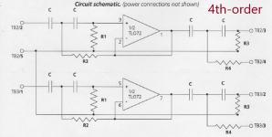
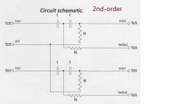
I have a 4th-order high-pass filter crossover module. I'd like to use it only as a 2nd-order high-pass filter.
Please help me how can I rewire it to achieve the goal?
I have a 4th-order high-pass filter crossover module. I'd like to use it only as a 2nd-order high-pass filter.
Please help me how can I rewire it to achieve the goal?
Attachments

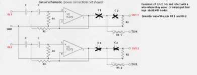
Here is my idea.
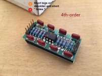
I think to completely remove the TL072s out of the board, then, tap the pin no. 2, 3, 5, and 6 of the TL072's sockets to be used.
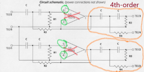
But I don't know if I can leave the unused components (in the orange circle) at their place or should I remove them as well?
Will this idea work?
I think to completely remove the TL072s out of the board, then, tap the pin no. 2, 3, 5, and 6 of the TL072's sockets to be used.
But I don't know if I can leave the unused components (in the orange circle) at their place or should I remove them as well?
Will this idea work?
Attachments
I'm afraid that there may exist another TL072 on somewhere outside the module.
To my understanding, the 4th-order active filter is created by cascading two 2nd-order filters. Thus, each 2nd-order circuit have its own TL072.
And the TL072 presented on the 4th-order module is a part of the second 2nd-order filters. However, this is only my assumption.
To my understanding, the 4th-order active filter is created by cascading two 2nd-order filters. Thus, each 2nd-order circuit have its own TL072.
And the TL072 presented on the 4th-order module is a part of the second 2nd-order filters. However, this is only my assumption.
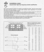
This board is probably a plug-in module that connects to another board with an op-amp voltage follower. The "passive filter" is then actually a second-order Sallen and Key active filter.
@xXBrunoXx see https://www.diyaudio.com/community/...ting-a-higher-order-slope.402037/post-7421406 for some context.
@xXBrunoXx see https://www.diyaudio.com/community/...ting-a-higher-order-slope.402037/post-7421406 for some context.

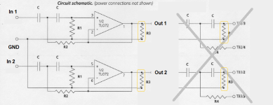
The simplest solution is to add two wires, one from each op-amp output to the corresponding module output, and leave everything on the board. The capacitors of the second filter section are then bypassed. Restoring the modules to their original state then only requires the removal of the two wires.
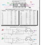
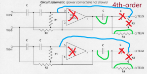
Here is the new diagram that I try to draw by myself.
Can anyone please check it whether it would work or not?
The red crosses refer to removal. The green lines refer to bypassing. And the blue lines are adding wires.
Can anyone please check it whether it would work or not?
The red crosses refer to removal. The green lines refer to bypassing. And the blue lines are adding wires.
Attachments
Last edited:
Now, I’m thinking it may be easier to build a second-order module than modifying the existing fourth-order module. What do you think about it?
However, since I have very little knowledge about designing the PCB, could anyone please help drawing the PCB schematic regarding the picture attached in post #9?
However, since I have very little knowledge about designing the PCB, could anyone please help drawing the PCB schematic regarding the picture attached in post #9?
Try here: https://sound-au.com/project81.htm You can buy a PCB from Rod also which makes things much simpler.
Yes, that should also work.Here is the new diagram that I try to draw by myself.
Can anyone please check it whether it would work or not?
The red crosses refer to removal. The green lines refer to bypassing. And the blue lines are adding wires.
Now, I’m thinking it may be easier to build a second-order module than modifying the existing fourth-order module. What do you think about it?
However, since I have very little knowledge about designing the PCB, could anyone please help drawing the PCB schematic regarding the picture attached in post #9?
A piece of perfboard cut to the right size should do.
- Home
- Source & Line
- Analog Line Level
- Please help modify this circuit (uncomplicated)