NAD 1300 Only One Channel Working

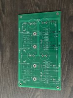
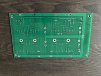
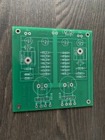
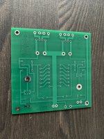
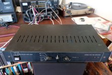
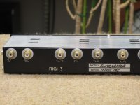
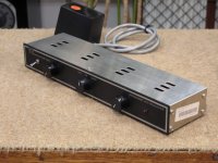
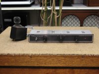
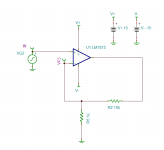
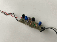
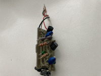
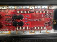
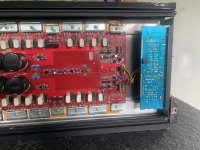
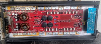
Picked up a NAD 1300 pre amp. Upon initial testing, knobs were scratchy, had a low hum and only one channel worked.

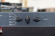
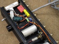
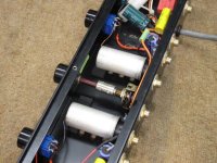
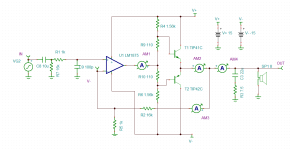
I used deoxit on all the knob/buttons, removed the old board glue (which I have heard can become a conductor) and inspected and resoldered some questionable joints, including the output RCA jack.

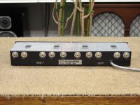
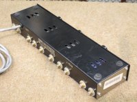
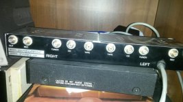
I also swapped out the RCA jacks from the pre amp to the amplifier and the bad channel appears to be the left side of the pre amp.

The hum is now gone as is the scratchiness, but still only have sound out of one speaker. However, when I plug in my headphones, both speakers work fine. Also, when the volume is all the way off, I can still faintly hear the music in the one working channel.

Any thoughts on what might be causing just the one speaker to work?

The one channel sounds great...would really like to hear what the pre amp sounds like in stereo!

Balanced Zen Line Stage Preamp PCB

PASS Balanced Zen Line Stage Preamplifier and Power Supply (PL45AR0 & PL45BR0) Boards. Items are brand new. I had to make 5 sets and used one set for myself, So I'm selling the rest. $30 plus shipping for 1 set.
Please let me know if you're interested.
Thanks.

Attachments

  • IMG_0157.jpg
    IMG_0157.jpg
    695.1 KB · Views: 177
  • IMG_0158.jpg
    IMG_0158.jpg
    665.4 KB · Views: 192
  • IMG_0159.jpg
    IMG_0159.jpg
    682.6 KB · Views: 154
  • IMG_0160.jpg
    IMG_0160.jpg
    664.3 KB · Views: 187

NAD 312 - no sign of life, need some help to know where to start

Hi! I’m new here. I don’t usually ask about my problems on forums because I usually find the answer I need from older posts.
I can’t find anything that could help me resolve my problem.

I bought a Nad 312 amplifier from a guy thinking it was at least powering up. Sadly, it doesn’t. There is not even a glimpse of sound or light.

I’ve already had experience repairing old amplifier when they gave some sign of life but the sound wasn’t great. Changing caps and putting contact cleaner spray.

As I said, there is no green light at the front and no apparent buzz or sound coming out of the transistors.
It must come from the beginning of the circuit on mains side, but I’m wondering if you had any idea of where to start looking.

Thanks for your help. Wish you a good day!

PS: here are some pictures of the amp circuit

IMG_8357.jpeg

IMG_8358.jpeg

IMG_8359.jpeg

IMG_8360.jpeg

IMG_8361.jpeg

JBL D2430H D2 compression driver bolt size

Hi gang, I recently bought the jBl D2 I mounted it on a car horn that’s a 1.4” horn and my goodness what a good driver.

By far , the best CD I’ve ever used. I like it better then the TAD TD2001. This JBL has the best highs I’ve ever heard…

So I’m buying another set and adapting them to another horn, the other horn which is better, doesn’t have the holes drilled for the bolt pattern,..

Does anyone know the bolt patter offset or know where I can find a drawing?

Thanks in advance

Andrew
B4665109-3C92-4F4A-B0FD-0126E7101A66.jpeg
A2D81D7C-4131-48A8-B5E4-9590C7EC5217.jpeg
1F07A0DF-CBB3-45F7-8385-6CABF4BE9D0E.jpeg

Miro NOS TDA1540 DAC in Simultaneous Mode

Sold.


This is a NOS I2S to simultaneous mode TDA1540 dac board designed by Miro. I have built two boards, and i am only keeping one board for my own system. I bought enough spares to populate 5 boards (MOQ by JLCPCB 😀 ) but i only managed to complete two at this moment. It is built with care and high quality parts, tested to work with stability. Your own PSU and i2s source is required to complete this DAC for it to sing.

The DEM decoupling film caps are a mix of good quality Shinyei and Rubycon. PSU Decoupling caps are good quality Panasonic FM (even lower impedance than FC series), bypassed with Epcos film caps. Resistors used are either Vishay or KOA. IV op amp is a pair of genuine OPA604 , which i have kept for years but they are totally unused and only for tests of this DAC.

This sale also includes a programmed CPLD board (the blue board with Alter Max II chip). It receives i2s signal from your source, converts it to offset-binary data needed for TDA1540 DAC. The VHDL code is written by Miro, and i have loaded the program to the CPLD board so that you don't need to bother about programming issues. Miro has a tutorial on how to program the CPLD board if you are interested to find out more, although this has been done by me.
https://electrodac.blogspot.com/p/tutorial-how-to-programm-altera-cpld.html

The CPLD board has been wired to the DAC inputs by soldering. Trust me, it is more reliable and sound better than just using Dupont cables with connectors. I had occasional weird noises when i used those because i find that sometimes the connection is not tight fit and moved a little. With the signals at those frequencies, loose connections is a problem.

So basically everything is wired up and tested, and will be shipped as such. Get a i2s source of your own, some psu boards and transformers, connectors and box it up for a complete dac.

This dac is designed by Miro and more info can be found here :
https://www.diyaudio.com/community/...s-input-nos-r-2r.354078/page-309#post-7272246

Miro also designed the PSU for this dac (not included in this sale):
https://www.diyaudio.com/community/...s-input-nos-r-2r.354078/page-309#post-7272253
Please study the power supply requirement carefully if you intend to use your own psu design.

Things to note :
1. All components, including the pair of TDA1540 chips and op amp are new, which is only used for the testing of this DAC.
2. Do read the design information provided above. I used all the information to complete and test the DAC.
3. Although the DAC board has been tested to be working, it is still wise to know and follow the start up instructions in the link provided above : https://www.diyaudio.com/community/...s-input-nos-r-2r.354078/page-309#post-7272246
4. This sale is for the TDA1540 DAC board + CPLD board only. PSU and USB-i2s board in the pictures below is for illustration only.

Price for the working DAC and CPLD board (as boxed in red in the picture attached below) is 220USD, including shipping worldwide registered. And as usual i will buy coffee for Miro. 🙂
  • Like
Reactions: yogiDIYbear

Help for hard to find Off-On-On switch

I've been searching high and low but couldn't find this type of switch. I modified the picture to eliminate the connection at "2":
https://global.discourse-cdn.com/digikey/original/1X/9575ce4e87e3ee1bef34244ec4c7bc2e1f66377c.jpg

Off-Mom-Mom.jpg


The purpose is to avoid relays in a power amp by first switching on the power -which has turn-on thumps- and with a second throw switching on the speakers, keeping the power up of course. I think this is a very elegant solution.

I found these https://www.digikey.be/nl/products/detail/e-switch/PB300DTQ/6126492
but 0,3A @ 28VDC is not suited for power and speaker connections.

Over here is exactly what I'm looking for so perhaps the tube guys can point me to anything useful:
https://groupdiy.com/threads/power-on-off-thumps-and-plops.77677/post-990387

Thanks for any help,
Hugo

Attachments

  • Off-Mom-Mom.jpg
    Off-Mom-Mom.jpg
    18.8 KB · Views: 87

Kenwood L08M circuit discrepency

I am working on another pair of L08M's , one of which has some fried resistors. In checking the transistors around these, I removed Q25 and Q27 only to find they are both NPN, Q25 being a 2SC1279 and Q27 being a 2SC2378, both of which are identified as such in the tranistor listing of the circuit.

However, the schematic of the circuit shows an NPN/PNP pair in a symmetrical arrangement, with the other pair of Q26 being a 2SC2378n and Q28 being a 2SA1023.

Am I missing something here?

Peter
btw circuit attached

Attachments

AUDIOMOBILE SA-1000 Power transistor T0-3 type #0602016 8101 blown and seek a replacement(s)

Greetings I own a 45 year old amp, AUDIOMOBILE SA-1000. Power transistor blown. Its a T0-3 type, "S" brand "SOLITRON" I think

Numbers on it are 0602016 8101

I cant find anything online, Uggggggg any help will be much appreciated, need new ones as well as some advice in regards to these blowing. My 45 year old amps are all working fine BUT this particular one. It ran hard for a while in my other car, but after it thermal shut down I pulled it but I think i hurt it. Been blowing output transistors (2) so far and now.... Power source is dead. This poor amp. LOL....

I just bought a couple more SA-1000's so I will have spares to blow up soon. Would like to get this one fixed.

Any help, THANKS!!!

BDBD 2022

VTL Pre-Amplifiers - Overview wanted for all older Models

VTL Pre-Amplifiers - Overview wanted for all older Models

Until now I have found this models:
  • without model/type naming (Stereo RIAA Pre-Amplifier - maybe first version) - U.K. made (HAND BUILD IN GREAT BRITAIN)
  • MAXIMAL (two different front plate designs) - go to
https://www.diyaudio.com/community/threads/schematic-wanted-for-vtl-preamp-maximal.158725/page-2
- MAXLINE (same as MAXIMAL but without PCB area for RIAA-Phono MM stage) - go to
https://www.diyaudio.com/community/threads/schematic-wanted-for-vtl-preamp-maximal.158725/page-2
  • INTEGRATOR
  • ADL DELUXE
  • SUPER DELUXE
  • THE ULTIMATE PRE-AMPLIFIER (Dual Mono)
https://www.diyaudio.com/community/...ded-vtl-120-deluxe-or-ultimate-preamp.400749/

some URL's:
https://www.vtl.com/about-vtl/who-we-are/
https://www.stereophile.com/features/607vtlfeat/
https://www.stereophile.com/interviews/david_manley_tubes_logic_amp_audiophile_sound/index.html
https://www.diyaudio.com/community/threads/vtl-book-david-manley.396522/
https://www.diyaudio.com/community/threads/wtb-the-vacuum-tube-logic-book-david-manley.356839/
https://www.usaudiomart.com/details...id-manley-kt90-kt99-kt88-6550/images/4312232/
https://www.worthpoint.com/worthopedia/vacuum-tube-logic-book-david-manley-1657481534
https://www.aussieaudiomart.com/det...id-manley-kt90-kt99-kt88-6550/images/4312230/
https://www.audiosciencereview.com/forum/index.php?threads/david-manley-vtl-book-4-loan.28455/
https://rec.audio.tubes.narkive.com/oZGxbXgU/in-praise-of-the-manila-book
https://www.eserviceinfo.com/preview_html.php?fileid=212756&previewid=190321
https://www.frihu.com/un-roehriges/vtl-roehrenverstaerker/

https://www.diyaudio.com/community/...ded-vtl-120-deluxe-or-ultimate-preamp.400749/
https://www.diyaudio.com/community/threads/schematic-wanted-for-vtl-preamp-maximal.158725/
https://www.diyaudio.com/community/threads/vtl-deluxe-tube-mystery.280724/
https://www.diyaudio.com/community/threads/help-with-vtl-preamp.40259/ (INTEGRATOR)
https://www.diyaudio.com/community/...e-valve-pre-amplifier-by-david-manley.349885/ (ADL)

Attachments

  • VTL without Model-No front-I.jpg
    VTL without Model-No front-I.jpg
    94.4 KB · Views: 186
  • VTL without Model-No front-II.jpg
    VTL without Model-No front-II.jpg
    97.7 KB · Views: 147
  • VTL without Model-No rear.jpg
    VTL without Model-No rear.jpg
    150.2 KB · Views: 171
  • VTL Integrator open-top-I.jpg
    VTL Integrator open-top-I.jpg
    107.5 KB · Views: 206
  • VTL Integrator open-top-II.jpg
    VTL Integrator open-top-II.jpg
    97.9 KB · Views: 203
  • VTL Integrator open-top-III.jpg
    VTL Integrator open-top-III.jpg
    116.4 KB · Views: 294
  • VTL Integrator open-top-IV.jpg
    VTL Integrator open-top-IV.jpg
    103 KB · Views: 217
  • VTL Integrator rear-I.jpg
    VTL Integrator rear-I.jpg
    85.1 KB · Views: 200
  • VTL Integrator rear-II.jpg
    VTL Integrator rear-II.jpg
    90.4 KB · Views: 194
  • VTL Integrator rear-IIV.jpg
    VTL Integrator rear-IIV.jpg
    62.4 KB · Views: 189
  • VTL Integrator rear-IX.jpg
    VTL Integrator rear-IX.jpg
    74.3 KB · Views: 190
  • VTL Integrator rear-X.jpg
    VTL Integrator rear-X.jpg
    72.7 KB · Views: 177
  • VTL Integrator front-IV.jpg
    VTL Integrator front-IV.jpg
    88.6 KB · Views: 233
  • VTL Integrator front-III.jpg
    VTL Integrator front-III.jpg
    88.1 KB · Views: 224
  • VTL Integrator front-IV.jpg
    VTL Integrator front-IV.jpg
    88.6 KB · Views: 194

Preamp Tubes matching in circuit

Hi guys,

I was wondering if matching preamp tubes in an actual circuit by measuring Ia (anode current) is a valid matching method.

I've ordered a bunch of Russian tubes that are supposedly matched. They come with a nice sticker and matching Ia and S numbers. When I place each tube in the same circuit and same position and measure Ia, I get various values that are sometimes 30% different than its matched tube. Does this mean that they're not matched?

Is placing the tubes one by one in the same position and matching them based on their Ia draw a valid way of matching them?

My circuit is the Aikido preamp using the Russian 6N2P and 6N1P.

Thanks

Alpine 3566 problems powering up and un-muting

LATCH problem, amp will mostly power up with just B+ and ground connected - it'll draw 2.6A and the status/power LEDs go green. +-22vDC and +-28vDC rails referencing secondary ground, but then referencing amp ground the rails are offset by 12v meaning secondary voltages are not well centered only when RCAs are disconnected though. 5M Ohms between RCA shields, non-bridging terminals and B- indicating a floating condition.

Amp passes barely a sound indicating possible muting issue.

Starting with LATCH problem, REM doesn't do anything. Taking a look at IC703, Q7027/Q728 now...

The Loudspeaker III by T. G.

Hi,

Brandnew design... The-Loudspeaker-III

tweeter Horn between the mid and the bass driver.
What do you think of it, please ?
The horn is flipped 6% toward the ceilling, . And the center to center is huge. Why is it not an issue ?

Can you please comment about that ? Is it time aligned or just "lobed" ? Still symetric LR12 ???


Ok, such loudspeaker must have dynamic and slam, but can it has a good soundstage and good enough fusion of the drivers ?

I2S DSD Playback issue on RPi4

I built a Raspberry Pi4 streamer with an I2S HAT (that supports DSD 512 out) to use with my Denafrips Pontus II DAC and installed Moode OS on it. The set up has been fairly straightforward. I hear a strangely mild white/hissing noise from the speakers when I play DSD files. Clarity and volume also dips to the point it sounds worse than FLAC/MP3 files. A bit more context on what I've tried-
  1. I matched the I2S PIN configuration on the I2S HAT with the Pontus II (PIN setting 5)
  2. FLAC/MP3 plays amazingly well with so such static/hissing noise.
  3. Played the DSD track from NAS and locally from the RPi4 SD card. I hear the static in both set up.
  4. Moode player shows DSD 2.822 MHz as the playback bitrate on its display, but Pontus II only lights up 48Khz and 4X LEDs. DSD LED doesn't light up.
  5. I've set 'DSD Native' as the playback setting on Moode. I tried 'DSD Over PCM' but there is no sound output at all.
Any ideas on what might be causing this issue and how I can resolve it? Thanks in advance! For next steps I plan to remove the I2S HAT and try USB output to DAC.

Link to the I2S HAT I'm using: https://www.aliexpress.us/item/3256803457718766.html

Model 91 schematic?

Does anyone know where online I can find a schematic of the Western Electric "model 91" amp? I can't seem to locate one.

I hear it described as a classic. The single pentode voltage amp/driver stage is interesting. Any thoughts on a #32 pentode driving a #45? I have two laying around.
I can't decide whether to do that, or just use a 6F8-G direct-coupled.:scratch2:

Joel

connecting multiple PSUs together to supply different rails???

Hi,
I was given an old audio processor but it doesn't have a psu.
It requires +/-12v DC, and 5V DC. Unlike most computer psu's a high current -12v rail is required.
I can't find an off-the-shelf PSU that will provide exactly what I need so I was wondering if I could use multiple PSU's to do the job?
So If I have 2 x 12v psu's and connect the + from one to the - of the other that gives me the +/-12v I require.
I have another 5v psu I can use, so should I connect all the 0v points together?
Here is a rough diagram that will hopefully explain what I mean:
PSU example.png


Please let me know what you think.

  • Locked
Elsinore MFC kit complete with assembled crossovers

SOLD> Elsinore Mk 6 MFC speaker crossovers with upgraded components and assembled by one of the forum experts. There's about $700 in these. Looking for $375 shipped to lower 48. With parts supplies being as sketchy as they are, if you're planning an Elsinore build this is the easy way to do it and you're getting better parts for less than sourcing the standard parts.

Aleph H Schematic - Revealed at Last

Many ... many ... many moons ago, I adapted the Nelson Pass` Aleph circuit topology to build a nifty, but ridiculously overbuild headphone amplifier that I named the Aleph H. I thought it was pretty cool, and circumstances came about that presented the opportunity to have my DIY project reviewed by Srajan Ebaen of 6Moons. Turns out Srajan liked it too and gave it a very positive review.

Somehow, I just never got around to publishing the schematic here for others to use. Periodically through the years I have had pokes from diyAudio members who have read the review and want to build my version, given its reviewed and 6Moons approved status. I have always shared with those that asked, but stupidly never taken the extra few moments to post it here.

That laziness ends here! :whip:

I have finally attached the schematic for the ciruit I built.

A couple of important notes:

1) The component numbers in my schematic DO NOT MATCH with the component numbers for the Aleph-Mini group buy boards. Be careful to ensure the right components end up in the right circuit locations.

2) All resistors are 0.25W rated except for the ones labelled in my schematic as R22, R23, R29 and R35, which are 3W rated.

Please forgive my excessive tardiness, and hopefully those who buikld this circuit will enjoy it as much as I do.

Attachments

  • Aleph H Schematic.GIF
    Aleph H Schematic.GIF
    31.6 KB · Views: 6,283

Tango FX-40-5 Output Transformers (Pair)

These are used but in superb condition. Ideal for 45, 2a3 or 300b push-pull.
I am looking for 300E for the pair plus shipping.

These are original Hirata Tango transformers. Secondary connection for 4, 8 and 16 ohm.

My email milosnesic606@gmail.com

Attachments

  • 20230703_200509.jpg
    20230703_200509.jpg
    493.2 KB · Views: 177
  • 20230703_200401.jpg
    20230703_200401.jpg
    363.3 KB · Views: 173
  • 20230703_200246.jpg
    20230703_200246.jpg
    486.1 KB · Views: 188

ATM31R mod recommendations

Hello diyAudio,

I just created this account because I am looking for some help with my first mic-mod. I got 4 of this old ATM31R microphones. I really like their look and also the capsule doesn't sound too bad, but they are quite noisy. They work well if I use them with loud sources and for close setups. But in situations where they need more gain the hiss is quite noticeable. So I was wondering if I can get more out of them. I can try to redraw the schematic. I've done some mods before and I am not new to diy. But I am no expert in electronics

Transistors are K223 and C1775. Any recommendations 🙂? Maybe try some new caps? Or different transformer to get more gain?

Thanks in advance
Matthias

Attachments

  • tempImagegAHoGN.jpg
    tempImagegAHoGN.jpg
    234.8 KB · Views: 81
  • tempImagexEnphn.gif
    tempImagexEnphn.gif
    829.6 KB · Views: 80
  • tempImage0Frmk4.gif
    tempImage0Frmk4.gif
    1 MB · Views: 84
  • tempImageIqfezu.gif
    tempImageIqfezu.gif
    1 MB · Views: 77
  • tempImagevFiFPJ.gif
    tempImagevFiFPJ.gif
    1 MB · Views: 87

SSE finished, some questions

Just finished another SSE built. Got some question about biasing. I used Hammond 374BX and EL34 tubes. While using 5AR4 rectifier tube, I measured B+ 428V, Plate 424V, Cathode 30V and I use a 560 Ohm bias resistor. This computes to 53 mA biasing current and (424 - 30) X 0.053 = 21 W dissipation.
Shall I drop the resistor to 450 Ohm or so to bring the current up to 66 mA like what George specified in his design?

Attachments

  • tubelabSSEBottom.jpeg
    tubelabSSEBottom.jpeg
    153.4 KB · Views: 188
  • tubelabSSEAmpTop.jpeg
    tubelabSSEAmpTop.jpeg
    117.3 KB · Views: 189

Now This is a sub! Bertha...W bin

I stumbled upon these renderings/plans and i am pretty darn sure that these are the subs used in the GSA system at district 36 in nyc. The bass from 4 of these on a small(ish) dance floor is unreal!! As i mentioned in another thread, this system produces the strongest bass i have ever heard! (i've been to my fair share of clubs with good systems installed)

here they are, the EAW bertha...

An externally hosted image should be here but it was not working when we last tested it.

bertha1.jpg

bertha2.jpg

An externally hosted image should be here but it was not working when we last tested it.

here they are in the GSA stack...
An externally hosted image should be here but it was not working when we last tested it.

ultimastack1.jpg

and im pretty sure Gary Stewart uses the crown 5002 to power each one...so with two woofers and bridged on that amp i figure about 5000rms? 😀
zouk6.jpg


obviously these are permanent install only and they are not meant to be moved around at all.

I'm Back and it's time for a new Near / Mid field Monitor. Thoughts and Stuff.

Well - It's been many years since I built my ONKEN Full Range with all your help, of course.
So it's time for another build, you know, now I have had a rest. 😍.
I want to design and build a nice multi way Studio Monitor for my Home Recording Studio. Possibly ending up with a 7:1. But wait....just a Stereo Pair to begin.
Anyway, I was inspired by this little "Mini Rig" (a mini version of the classic main monitors found in commercial studios) I found on Pinterest (Steven Walker; builder):
PartsExpress.jpg
I have the list of speakers used - there are PartsExpress / Dayton Audio Paper Cone Reference speakers - 6". I could go a little larger (enclosure) - or stick with something this size. Could go Dayton, could go...Fostex! I certainly DO want this horizontal axis. And I definitely DO NOT want rear Porting. But I DO want textile / silk dome type Tweeterers. Just like my Event 2030 BAS - current monitors.
Have looked at the full size versions of these at Wilmslow-Audio: And there is an additional "Mid/Tweeter"...something to think about.
So: Hello Again and:
1. Thoughts?
2. So what Speaker Building Software are we all using these days? I have Winows, Osx / linux if needed. Hmm... any good Open Source/Donation Apps?

Thank You, Ahhh, It's good to be back amongst, well, people who at least understand.
MWOAH! 😍

PS: STILL listening to those Onken's, Every Day, amped up to the big TV my wife insists on...And so are my Children ! Yes! I have 2 nowadays. Baby Shark sounds GREAT through them😀. (the Onken's, not the childr.....you get the idea!)

Xx. T

Scanspeak FRD files for Vituix

Hi everyone

I am trying to get to grips with learning to use Vituix but I am falling at the first hurdle due to not being able to find frd files for the drivers that I am using.
Can anyone point me in the direction of where I would find frd file for the following drivers:

Scanspeak - D3004/660000 (tweeter)
Scanspeak - 15W/4531G00 (mid/bass)
Scanspeak - 18W/8531G00 (woofer)
SB Acoustics - SB23MFCL45-8 (sub woofer)

I've probably missed something obvious but I can't find them anywhere. Any help with this will be appreciated.

Thanks

Paul

Dynaudio BM15A amplifier modification

I have a pair of dynaudio bm15a that I have never quite been happy with the sound of . theres a slight harshness to the trebble i have the passive version that uses a different tweeter and crossover frequency and i much prefer the sound of those .
I had the idea of using the amplifier and bass driver and altering the inbuilt active crossover to lower the crossover frequency to allow me to crossover to a pair of avi nuetrons about 300htz using their internal passive crossover turning both speakers into one set of three way speakers .
could someone please have a look at the schematic and tell me if this is realistic or not . if not could I somehow patch in my own active crossover before the amplifier part of the pcb and still make use of the amp
many thanks
ps it's the mk2 version I have

Attachments

Two-transistor Vbe multiplier

I'm trying to use the Vbe multiplier (d) shown in http://www.renardson-audio.com/B-amp.html but I'm not sure which one is the "sensor" transistor.
D. Self refers to the same circuit in his "Audio Power Amplifier design" 6th edition book: "The first transistor is the sensor." But cant say which is the "first".
I would appreciate some help.
Thanks.

Attachments

  • vbemult.gif
    vbemult.gif
    4.3 KB · Views: 713

Ming Da MC-3008-A2 Mono Blocks

Very curious, can anyone comment on the sound and quality of the Ming Da MC-3008-A2 40W Mono Blocks from Pacific Valve?...

I can't find any reviews. The tube topology is (2)12AX7, (2)12AU7, (2)300B, (2)805 tubes. I don't have a schematic, but is it a good design with decent OPT?...

I am going to run it as a integrated amp with a Cambridge Audio CDP 640v2. Speakers are Paradigm S40 v3.

Thanks Guys!

Question for old-timers, before the Internet old-timers.

On another thread I discussed buying a random set of cheap, used speakers in order to transplant the drivers from my ugly Schneiders. I abandoned the idea but the wheels were already in motion. I had committed to buy some speakers with 11ltr cabinets for £1.

On the back the label says, "Made in Sweden for Tandy UK" & "Carbon-Fibre Woofer."
Tandy went bust last century, back when carbon-fibre cost a fortune. I just need to check with connoisseurs that I'm not emptying the contents of the Holy Grail down the crapper so I can make an Ikea footrest.

Power Jack Mounting Material

I’m installing this DC power jack on a little boombox build and want to know how important the mounting material is. I no longer have the acrylic mounting plate that parts express sells, but I do have some scrap plastic (from a container lid) I’m about to use.

Would plastic be unsafe and for future builds would wood or metal mounting plates be safe?

Thanks!

Input transformer for Pascal S PRO2

Dear All,

This is my first posting here, my question is if a 4:1 input transformer would work on the Pascal S PRO2 module.
The gain of the S PRO2 is 26db and it has a 2k2 input impedance.
My tube preamp has 20db gain from parallel 12au7, anode output, output impedance 2k5.
I found the following transformers: Lundahl LL1545 and Jensen JT 10 KB-D.
Would this work or will I loose too much gain because of the 4:1 transformers?
A alternative could be a output transformer in my preamp.

Any thoughts or experience about/with this?
Kind regards!

Difference in Inductance - How does it affect MM Cartridge sound?

Hi!

Inductance of MM cartridges plays a role in their sound signature. Obviously i'm not attesting anything new or revelatory.

Not sure i understand exactly how it affects performance but was pretty surprised to find out how much different the same stylus sounded on cartridge bodies with different inductance (otherwise identical).

The two cartridge bodies belong to the same family, with interchangeable styli.

One is a Shure M55E (pre-2000, Mexico made) and the other is a Shure M44-7 (post-2000, Mexico made). Used the same stylus on both for evaluation (N55E Improved, original stylus). Cartridge headshell used, turntable, VTF and all the other variables were kept identical.

According to my LCR meter, the cartridges showed the following values:

Shure M44-7
Resistance: R 681Ω, L 680Ω
Inductance: R 568mH, L 606mH

Shure M55E
Resistance: R 690Ω, L 690Ω
Inductance: R 759mH, L 721mH

Didn't expect them to sound as different as they did, given the above values.

Resistance is almost identical, being only 9Ω and 10Ω higher on M55E, for each channel respectively.

Differences in inductance are more pronounced though. 191mH and 115mH higher on the M55E, for each channel respectively.

Links to audio recordings of both cartridge bodies with same stylus:
Shure M44-7
Shure M55E

When i listen the two recordings, the one with the higher inductance (M55E) sounds substantially wider in terms of channel separation and with less pronounced high octaves. The other body (M44-7), has an overall brighter rendition with a somewhat collapsed soundstage in comparison.

So, is it down to the difference in inductance?
Maybe.

My only reservation is that there might be other factors affecting the result, which i'm unable to identify/measure.

Regards, Nikos.

Transcoding Dolby Pro Logic to 5.1 surround

Hi all,

I recently got a soundbar that doesn't correctly decode/upmix stereo matrix surround sound like Dolby Pro Logic, and I was wondering if there might be a DIY way to take a DPL input and transcode it into something the soundbar will recognise (e.g. DTS 5.1 via optical, or maybe something through HDMI).

I am wondering about a couple of possible ways I might go about this:

1. Using hardware decoding
Seems like there are chips you can buy that decode this stuff. So perhaps I could build a device that feeds a stereo signal through the chips, and then outputs it as a true 5.1 surround signal.
2. Using a DSP
I have been looking at various Raspberry Pi solutions for DSP. I found a github that seems to have profiles for EqualizerAPO that purport to be able to at least somewhat properly upmix these signals (here). So I am thinking maybe I could achieve something similar using Like a HiFiBerry DAC+ Digi with a Raspberry Pi. It would need to be fairly low latency to meet my needs though.

I am not super experienced in this area, I can code and solder but I'm not much of an electrical engineer.. still I would be interested in attempting something like this as a kind of long term project/learning experience. If anyone here has any insight into whether something like this is practical/possible I would be very interested to hear about it! I understand there are some licensing issues around this stuff, but a lot of the discussions I have read online are really old so I am hoping there has been some progress I haven't uncovered in my search.

Any similar projects/recommended reading would also be welcome.

And, if someone has already solved this problem - well that would be awesome!

Thanks.

For Sale Delta Audio Leach Amp

If there is interest I plan to sell a Leech Amp based on Delta Audio 10 transistor design (on eBay). Very nice sounding amp, but I have accumulated too many amplifiers, and this one needs to be rehoused from its prototyping case. With the toroidal transformer it is very heavy, so I would entertain selling the channels mounted on the heatsinks separate from the transformer. I am thinking $100 per channel ($200 for the pair) plus extra for the Bridgeport magnetics transformer (I have to look this up), plus the packing and shipping cost (local pickup in Connecticut possible)

Let me know if the price seems fair.

300B schematic recommendations

Hi Folks,

I already have a pair of this output transformers:
c15fca_935edb6d3ed6479a94189931dbc492bf~mv2_d_2785_2084_s_2.jpg


Primary: 2,5k or 3,4k
18W

I would like to build a 300b stereo amplifier or two mono amplifiers for my HiFI.

For the moment I have a SE PCL 86 amplifier with 4watts, which is actually enough for my speakers, but I hope to achieve 2x8watts with the 300b's.

There are a lot of schematics:
6SN7-300B-Single-Ended-Tube-Amp-Schematic.jpg


27007945296_230cbf611d_o.gif


schematic.gif


I would like to know which one fits my output transformer best - or if there are other schematics - feel free to post them here 😉

What would also be nice: If the amp wouldn't need a preamp - I thought about an aikido preamp to drive the 300b but the schematics from tubecad require different primary impedances.

Have a nice day!
Felix

Mcintosh MC431M in power guard

I have a Mcintosh MC431M, when it is turned on, there is a loud noise in the speakers before the power guard light goes on.
I have removed it from the car and connected it to a power supply without speakers, same thing happens, it goes into power guard mode.
I have opened it up so I can see the circuit boards and components, there are no visible caps leaking or anything.
The problem seems similar to https://www.diyaudio.com/community/threads/pls-help-strange-mcintosh-mc431m-problem.165344/
But there was no solution posted. I only know basic electronics, and I can't find anyone to help with the repair in my area. Does anyone have any clues where to start?

Question regarding dipole driver

Hi all. I have a question regarding dipole drivers. Situation is I have a set of 2-way speakers with a low 1.5khz crossover. Tweeters are toast and no replacements are available. Having looked around I have found a ribbon tweeter that is a near perfect replacement. The only issue is it is a dipole design while the speakers are a sealed box. My question is what effect will the sealed box have on the tweeter response? I know there are a ton of variables so I don't expect a specific answer but more of a generalized one.... will it change low end response of the tweeter or it's power handling or efficiency? Since I want to use it in a sealed box anyway would it work better to seal the back of the driver? Thanks for any insight.

Phonic P8A reloaded

Hi everyone,

I want to share with you my experience of the last half a year spent modifying these "monitors" made by Phonic. After reading the only review online ( Test: Phonic P8A - Studio - AMAZONA.de ) I acquired them for something like 200$ which I considered to be a goo deal. And it is, to certain extent - the P8A have some issues.

Let's start with the bad:
  • Unknown origin metal dome tweeter, slightly different model in each speaker (!) that sounded extremely harsh
  • Front firing ports are non-functional. The extremely cheap plastic they were made of was all warped, God know how someone could manufacture this. (No photos, I threw them away but trust me those were THE worst imitations of ports I've seen)
  • Extremely unpleasant sound, with weak bass, elevated 1kHz range I had my ears hurt after an hour of listening.
  • The crossover was all over the place, I have the transfer function of xovers, see attachments. Obviously the "24dB/oct LR" is a bit overstated in the specs. Not to mention the ridiculous 15dB boost at 20kHz.

Now the good:
  • Reasonable build quality, nice finish of the cabinet box.
  • Very nice and compact amp design with toroid transformer (I'd estimate about 250W), all enclosed in nice metal casing.
  • Plenty of circuitry to play with (2xTDA7293 for bass, another one for the tweeter, auto-off circuit, overload protection, plenty of opamps in the signal path to play with)
  • Nice looking woofer with cast frame, from the looks identical to the one used in Behringer B2031 ( http://i836.photobucket.com/albums/zz286/my_graphs/Behringer B2031P/DSC03709.jpg?t=1290059946 )

So now that I had a pair of crappy speakers, some spare money and a huge motivation to learn more about speaker building, I started modifying the hell out of them. Here's what I did:
  1. Relocated the ports to the sides of the cabinet, changing them to 4cm PVC tubing in the process (WinISD helped a lot)
  2. Completely refinished the cabinets
  3. Laid about 1" of rockwool on inside walls
  4. Changed the tweeters to Seas 27TFF
  5. Completely redesigned the crossover and settled on a mixed active/passive solution

See attchments 2 and 3 for what I ended up with. I'm very pleased with the sound and new appearance of the speakers, it was a long but very interesting journey to this point, with some quite radical design choices. There are things I'd do different now but that's probably the case with just about any project.

If anyone is interested, i can post some (a lot) more details.
K.

Attachments

  • p8a native xover.jpg
    p8a native xover.jpg
    86.3 KB · Views: 563
  • p8a finished spl.jpg
    p8a finished spl.jpg
    75 KB · Views: 545
  • IMG_2378.jpg
    IMG_2378.jpg
    261.4 KB · Views: 592

Visaton WG148R Waveguide: Highest SPL tweeter with flat faceplate?

There are several threads here about matching tweeters for the Visaton WG148R waveguide which is a powerful addition to the speaker designers' toolbox.

I am looking for a 1" dome, w/ flat faceplate, with the highest top-octave efficiency as possible. I want to match it to a woofer that's 94-95dB 2.83v/1m. The max efficiency of the system ends up being constrained by the tweeter.

Most 1" domes don't go past 91-92dB. In the top octave, mass prevails over horn coupling, so the waveguide won't increase the SPL much if at all in that range. Therefore we need a tweeter with high BL, low impedance, and low mass.

Also for this waveguide you need a flat faceplate, otherwise you have to mess around with gaskets and mods.

Are 28-29mm domes too big to match the WG148R?

Other threads have discussed SEAS and Peerless 25" domes, ie https://www.diyaudio.com/community/threads/xt25-visaton-wg-148-r-with-pictures.285240/ and https://heissmann-acoustics.de/en/test-wg148r-noferro-900/ but none of them reach into 94dB sensitivity territory.

Any suggestions?

18 Sound ND3ST

18 sound ND3ST compression driver. Barely used. Mostly employed for tests. No sign of use. See pictures.
The price for the pair is: 490€
European shipping is 25€, international shipping is 55€, if you want insured shipping please ask for price. Payment by PayPal, satispay or bank transfer in advance.
my email is franco.cauda@gmail.com

Attachments

  • IMG_1045.jpeg
    IMG_1045.jpeg
    600.1 KB · Views: 100
  • IMG_1044.jpeg
    IMG_1044.jpeg
    827.7 KB · Views: 108
  • IMG_1046.jpeg
    IMG_1046.jpeg
    604.4 KB · Views: 105
  • IMG_1047.jpeg
    IMG_1047.jpeg
    780.9 KB · Views: 127

Pioneer SX-1250/5590 EQ board issue

Having a problem with an SX-5590 that has a problem on the equalizer board. The receiver had already been serviced and recapped by a previous tech.

I couldn't duplicate the issue at first but then noticed a bulged cap (470uf, C12). When I pulled the cap it read 63uf so, I replaced it. After I replaced it I monitored the output of a 1khz sine wave on my scope, through the phono inputs (I use a little RIAA circuit in-line to match the signal before going to the input). What I noticed was at about 9:00 on the volume, the wave would get distorted and then it would trip into protection. Lowering the volume took it out of protection but I didn't like that distortion. So I pulled the board and replaced all the transistor pairs in the right channel where I saw the bulged cap, and when I tested, R44 and R45 (150r) smoked. Nothing was installed backwards, and I used the correct subs (KSA992, KSC1845) or so I presume based on research and other threads that give viable substitutes. Dim bulb does not protect the resistors from smoking. So I pulled the board again and went through rebuilding it; new caps (again), all transistors replaced including both 2SA850/628A with KSA1013, and replaced the burned resistors. Put back together, tested on the bulb, no smoke. Ran a signal through the phono stage for about 15 minutes and everything was fine but then R44 smoked again. R45 was fine. I checked D5 and it was shorted/open. Replaced it with a 1N5252B, replaced the resistor again, and the same thing happened on power up.

I've never had an EQ board smoke before. Any insights on where to look? Obviously I'd have to disconnect power to the EQ board to test the power supply otherwise it will just keep frying that resistor in the meantime.

IMG_5714.jpeg
IMG_5713.jpeg

Tone Control for LM3886

LM3886 based amp with sub output

I want to build a LM3686 gainclone based amp with sub output.

Im beginning to find parts – mainly the mechanical parts, but plan to begin making the pcb´s in late October.

I have come across a sew problems, so I hope you can help me out.

The Sub
Im planning to make the sub signal just like the left and right. But should I add extra electrolytic capacitors for the sub channel?
My plan is to use the sub, just as a supliment to my normal speakers(Old Rauna Njord), that might need a little extra in the lower frequencies.

How do I “Make” the sub signal? I would like to merge the left and right signal, and cut off the frequencies above lets say 500Hz. But I would like to be able to adjust the cutoff frequency with a digital potentiometer, so I can control the cutoff frequency with a micro.

Tone Control
I want a tonecontrol. But I want to be able to control it from my microprocesser and not by buttons. So it can be controlled with a digital potentiometer. This way I can make my amp really minimalistic, but still have the features that an integrated amp has.
So Im looking for a good 3 channel tonecontrol solution with bass, mid and treble and volume control.

Any links og suggestions is highly appreciated.


Peter

newbie question about RPi+Volumio/Moode sound quality

Hi there,

Before I ask my question here's a very little bit about what I have and what I'm trying t do.

I've recently been trying to evaluate different computer based digital audio streaming solutions.
My current setup is 2x Raspberry Pis, 1x 3B+ and/or 1x 4B.
USB to a Topping E50 then RCA to my amp then Duntech Marquis speakers.

I have my CDs ripped to FLAC and SACDs to DSD and sitting on a NUC running Win10 and available via a network share.

I'm currently trialling Volumio and Moode and trying to do AB listening tests.
Configuration of both is stock standard straight out of the box....no plugins, no CamilaDSP etc.
There is a slight but almost imperceptible difference between an RPi3B+ and the RPi4B with either software.

I was however surprised to hear quite a difference between Moode and Volumio.
Considering both should be able to deliver bit perfect streams to my DAC, can anyone advise why Volumio ad Moode sound different out of the box?

Thanks in advance.

Krell CD-1 Player: Successful repair of Remote Control unit

Purpose:
  • To share my experience repairing a Krell CD-1 player's remote control unit.
  • Although this content is relevant to both the Solid State and Digital Source forums, as the primary focus of this report is the identification and replacement of broken components, I felt best to share this content on the Parts forum.
Equipment:
  • Krell CD-1 player serial number 99209281 (Fig. 1), supplied with infra-red remote control (Fig. 2).
Krell_CD-1_Player.jpg

Figure 1: Krell CD-1 player, serial number 99209281 - photo taken August 2023.

Remote_Control.jpg

Figure 2: Krell CD-1 remote control unit - photo taken after repairing, August 2023.

Background:
  • This Krell CD-1 player I purchased new in 1992 from Loyalty Sound Ltd in Calgary, Canada. Overall, I was very pleased with the performance of this CD player throughout 10 years of worldwide assignments. Although it was in full working condition, sadly I had to put my Krell CD-1 into storage in 2001 due to shortage of living space.
  • Unfortunately, during the last international move the remote control unit got packed in a different box from the CD-1 player, with the 3 AAA batteries remaining inside the remote control unit. This led to leakage of the battery's electrolyte, further leading to corrosion and damage to the remote control's internal components rendering it inoperative (Fig. 3). Note corroded battery terminals, damaged electrolytic axial capacitor, broken (missing) resistor - more to come later.
Remote_Control_PCB.jpg

Figure 3: Remote control unit circuit board showing corroded, broken components.
  • Other than the Owner's Reference manual that came with my original purchase, I have no access to Krell's circuit diagrams or service instructions, and so contacted Krell customer service to enquire what could be done. Krell's Customer Operations Manager, Timothy Rogers kindly replied that it may be possible to send the unit back to Krell for repair, however with a minimum service charge of 1hr ($125) plus international shipping costs we deemed it probably wasn't worthwhile.
  • Although I had no experience with repairing a remote control unit, I decided to investigate and attempt local repair if possible.
Failed components:
  • With no circuit diagram, no service instructions and unable to identify the values of the corroded/damaged components presented a challenging puzzle.
  • After cleaning as best I could the circuit board (Fig. 3), I then attempted to recreate a circuit diagram by observing and continuity checking each of the circuit board traces. Hopefully, Figure 4 describes a reasonable recreation of the Infra-red transmitter circuitry, with the unidentifiable components labelled in Red.
Presumed circuitry of Krell CD-1 Remote Control.jpg

Figure 4. Presumed circuitry (broken) of Krell CD-1 remote control - infra-red transmitter section only.

Damaged Capacitor:
  • The only remaining legible markings were the number "10" and the letters "PHIL-". Judging from the blue jacket colour I assumed this to be a Philips electrolytic capacitor, rated 10 V.
  • Testing the capacitor out of circuit measured a capacitance of 17.2 uF and an ESR of 8.3 ohms. Presuming this to be a 22 uF, 10 V rated capacitor, the measured capacitance was low and the measured ESR was high, necessitating replacement.
  • This was replaced with a fresh 22 uF, 16 V rated electrolytic axial capacitor.
Broken/Missing Resistor:
  • Before this resistor fell apart and crumbled, I was lucky to observe three colour bands; 1st Blue, 2nd Red and 3rd Silver. This colour band combination equates to a resistance value of 0.62 ohms, which seemed suspiciously low.
  • Assuming the 1st and 2nd colour bands of Blue and Red respectively were correct, but unsure what the proper resistance value should be, I inspected the third colour bands of some actual resistors (Table 1).
Table_1.png

Table 1. Comparison of actual resistors, their resistance values vs. colour codes
  • Side note, I first learned the resistor colour code when I was a teenager in high school, where the Black coloured band signified a blank or non-value.
  • However, after researching this I now learned that the colour White can also be used to signify a blank or non-value, which solves the puzzle of the original installed resistor. The 3rd colour band was most likely White, not Silver - shows you can still learn something 50-years after high school!
  • So that's what I used, a fresh resistor of 62 ohms having colour bands; 1st Blue, 2nd Red and 3rd Black.
Test Measurement:
  • Still apprehensive whether a 62-ohm resistor was the correct value or not, and with no visible indication to the human eye whether the infra-red photodiodes were transmitting or not, I conducted a test to observe how the circuit performed. Test setup is described in Figures 5 and 6.
  1. 62-ohm resistor lightly tacked in place for the test.
  2. External 4.5 VDC supply connected to the battery terminals.
  3. Oscilloscope connected from the minus battery supply to anode of the two infra-red transmit diodes.
  4. Touch pad buttons were activated to start signal generation.
Oscilloscope_Test.jpg

Figure 5. Test setup - External 4.5 VDC connected to terminals, oscilloscope connected to battery minus terminal and photodiode's anode.

Test infra-red transmitter circuitry.jpg

Figure 6. Test of infra-red transmitter section after circuitry repaired.
  • To establish a baseline position of the oscilloscope trace, with no DC power applied the oscilloscope channel 2 input was grounded (Fig. 7).
Ground_Reference.JPG

Figure 7. Zero-signal reference, oscilloscope channel 2 grounded.
  • With the 4.5 VDC supply connected, a stable rest voltage of ~ 1.51 VDC was observed on channel 2 (Fig. 8).
Static_DC_Voltage.JPG

Figure 8. Rest condition, touch pad buttons not activated.
  • Finally, when pushing the buttons on the touch pad, different coded pulse trains could be observed. An example of one pulse train captured on the oscilloscope is displayed on channel 2 in Figure 9.
Sample_Pulse_Train.JPG

Figure 9. Active condition, example of a coded pulse train when touch pad button activated.
  • Based on this test result (Fig. 9), it showed the remote-control unit to be functioning.
  • After removing external DC power, the 62-ohm resistor was fixed properly to the circuit board (Fig. 10).
Repaired_Circuit.jpg

Figure 10: Repaired circuit board of remote control unit - note 62-ohm resistor colour coding Blue, Red, Black (not White).
  • Operating the remote control with the CD-1 player, I was pleased that 17 of the touchpad's 19 pushbuttons functioned properly, the only two inoperative buttons being the "PREV" and "NEXT" buttons. These two buttons are situated closest to the corroded battery terminals and probably became contaminated from the battery's leaking electrolyte. Still, 17 out of 19 working buttons is 90% functional (far better than 0% or having to scrap the remote control).
Next issue:
  • After operating reliably for several days, the remote control suddenly stopped working.
  • Opening the unit up again found nothing untoward, all replaced components still intact.
  • Tracing the signal flow from the touchpad confirmed control pulses of ~ 1.2 V amplitude were flowing to the input of the infra-red transmitter section (Figs. 11, 12).
Test Touchpad Control Pulses.jpg

Figure 11. Test of touchpad's control pulses.

Sample_Touchpad_Pulse_Train_In.JPG

Figure 12. Example of control pulses coming from touchpad when button activated - approx. 1.2V amplitude.
  • This test showed the touchpad and its digital circuitry were functioning properly, suggesting something wrong again in the infra-red transmitter circuit.
  • Suspecting the input transistor 2SC548B (#7003 in Fig. 11), a check of its Base-Emitter forward bias showed an unstable and strange voltage, > 0.9 V vs. an expected ~ 0.6 V (Fig. 13).
2SC548B_Forward_Bias_rising.jpg

Figure 13. Measured forward bias of original transistor 2SC548B - note unstable voltage with fluctuating final digit.

- The 2SC548 being an obsolete series I replaced it with a spare 2N3904 NPN transistor I had. A check of this transistor's Base-Emitter forward bias showed a typical ~ 0.6 V and stable (Fig. 14).
2N3904_Forward_Bias.jpg

Figure 14. Measured forward bias of replacement transistor 2N3904 - typical voltage value and stable.
  • With the new 2N3904 transistor installed in the circuit board pleased to report the remote control is now operational again!
  • Just a minor issue, the physical orientation of the Emitter and Collector leads is flipped between the original 2SC548B and the replacement 2N3904. The easy remedy is to install the replacement transistor 'backwards' to align the Emitter and Collector positions (Fig. 15).
2SC548B_replaced_by_2N3904.jpg

Figure 15. Orientation of transistor at 7002 (left) vs. reversed orientation of replaced transistor at 7003 (right).
  • What caused the original 2SC548B transistor to fail? It was only when I gently removed this failed transistor from the circuit board that I noticed its plastic case was broken (Fig. 16). One theory could be the leaked electrolyte from the batteries penetrated the transistor case causing it to weaken and eventually fail.
Broken_2SC548B.jpg

Figure 16. Original transistor 2SC548B with broken plastic case.

Final Notes:

  • The reason for this writing is to share my experience repairing the remote-control unit of a Krell CD-1 player, it's not to bypass factory repairs, just to share what worked for me. Hopefully no more failed components.
  • Finally with the circuit board installed back in its case (Fig 2.) and fresh AAA batteries installed, pleased to report the repaired remote-control unit now operates happily with my CD-1 player!
  • Like
Reactions: newvirus2008

TSE 2A3 C3

It wasn’t supposed to make a difference but, my monoblocks vastly improved when I replaced the recommended Elna 4700uf with something fancier. I’m not saying what I used so as to keep any discussion theoretical. I’m not shilling for anyone.

I understand that ac has a direct path to ground at the other (-) end of the filament but this cap sure looks like a cathode bypass cap across the 1 ohm filament of the 2A3.

The reason I became even curious about this is because I also recently built a 45 version TSE that utilised (fancy) filament regs (that have no cap at all there, in addition to other “thought-provoking” properties) and it sounded so good I thought my 2A3 amps were broken.

I’m curious what the ee’s and George think. Am I trippin?


While I’m here, I’d like to say thank you for all of it. I learned a lot from building these circuits and have enjoyed their sounds immensely over the years.


Jason

LM337: a new epidemic?

The power supply of my mckinnie pre-preamp died, so I bought a small 317/337 PS kit to replace it.
The negative leg didn't work, no biggy, I ordered a handful of LM337 from Aliexpress. All bad.
I ordered another small batch from eBay, Germany. All bad. It turned out they're the same items as Ali.
The prob appears to be some kind of a short between Vout and Adjust, so Vout is always ¦Vin¦ - 2V, regardless of the setting.
Out of curiosity, I ordered another batch from eBay China, but they've not arrived yet. We'll see if this is epidemic level.
Finally, I've got some NOS Motorola 337 from eBay France, and all is well.
I don't usually have problems with parts from Ali, but stay away from the 337 for now,

LM337-CN.jpg
LM337-bad.jpg
LM337-good.jpg
  • Like
Reactions: rockies914 and TNT

Group Buy for mosfets for FC CEN IV through hole US and Canada ONLY

Dear all,

This is a group buy for US and Canada residents only for ZVN3306/ZVP4424 matched sets for the FC CEN TH group buy.

Please list your name and the number of sets you would like. US and Canada residents ONLY.

I will compile the number of sets needed and in the future give an exact amount of dollars per set. At this time, cost is approximately $3.00 for a set and around $10.00 to ship. This is subject to change.
  • Like
Reactions: alazira

Solid Audio F2000 Demons

GD gents,
Does anyone have any schematics or similar schematics for solid audio f2000 amplifiers? The board is very similar to American Bass SQ3000 amplifier.

I got this one in and several demons to work out, severely mixed amplifier components, to-247 and to-220 in both channels, with the shorted components removed, the unit goes into protect. Disabling protect, the unit powers up ok with good rail and regulated voltages. But there seems to be DC at the R-ch Spk terminals.
Haven’t disassembled fully yet, still assessing.

Attachments

  • IMG_9566.jpeg
    IMG_9566.jpeg
    512.4 KB · Views: 167
  • IMG_9568.jpeg
    IMG_9568.jpeg
    648.5 KB · Views: 167
  • IMG_9569.jpeg
    IMG_9569.jpeg
    613.9 KB · Views: 146
  • IMG_9570.jpeg
    IMG_9570.jpeg
    599.1 KB · Views: 135
  • IMG_9567.jpeg
    IMG_9567.jpeg
    420.5 KB · Views: 152

  • Poll Poll
Found an old Fluke 8030A...

What would you do with an old Fluke 8030A in my place?

  • Keep it as it is and display it as a museum item as it's not worth using anymore

    Votes: 0 0.0%
  • Do a quick internal cleanup and use it for very basic stuff only

    Votes: 3 50.0%
  • Restore it as much as possible (new caps, resolder everything, cleanup contacts) and use it normally

    Votes: 3 50.0%
  • Restore it (as above) + have it recalibrated for everyday "workhorse" use

    Votes: 0 0.0%

Hi all,

while cleaning up my attic, I found an old Fluke 8030A bench Multimeter. It works, but shows imprecise readings. Getting rid of it is out of the question, but I don't know what I should do with it...

Cheers

Denis

Capacitor input causes Offset Increased

Recently made this schematic, and working properly, but my problem is without any capacitor when I connect from mobile out as a input direct there is no offset change or ZERO OFFSET WITH 1uma current, but I want to ad a opamp for that have input a cap but when I ad a cap offset goes 45mv , so do I need a servo circuit?? Or any circuit changes that will fix d problem 🙏

Spitfire Mk9 model made for me by my son

Hi guys, i thought i would share, what i think is a wonderfull model my son made for me

I used to make lots for him when he was a young boy, so he said he wanted to return the favour by making me one.

He does commisions so he is way better than i ever was, and i think you will agree, its pretty good as he works off the original design plans from supermarine and adds all of the wiring and pipework etc that doesnt come with the standard kit-he also replaces some items with more acurate after market parts 🙂

Attachments

  • IMG_20230802_080753.jpg
    IMG_20230802_080753.jpg
    560.7 KB · Views: 342
  • IMG_20230802_080845.jpg
    IMG_20230802_080845.jpg
    320.1 KB · Views: 344
  • IMG_20230802_080854.jpg
    IMG_20230802_080854.jpg
    373.2 KB · Views: 339
  • IMG_20230802_080956.jpg
    IMG_20230802_080956.jpg
    276.2 KB · Views: 329
  • IMG_20230802_081014.jpg
    IMG_20230802_081014.jpg
    288.5 KB · Views: 329

Transformer volume control - TVC by dvb

This stereo 23 steps transformer volume control is a 6th generation proprietary design. Its primary function is line level control volume but contains such a high quality permalloy that you can use it also - inverting cables in the back - as fixed step-up line level transformer or adaptable to DAC stages or MC step-up for moving coil cartridges!!! It is also small (actually the smallest I've seen), compact layout and nice looking 🙂

The basic version is a 1:1, 10k:10k, 80H@20Hz, but other transformer ratios can be made. The logarithmic curve is according with IEC 60393-1 code 15A law. For this 1:1 version see the THD figures for 0.7Vrms at highest step (with the soundcard having about 0.0005% THD in loopback), also the frequency response 10-100kHz, these specs being of course in the same ballpark at any step.

Price: 650 Euro w/o shipping for basic version
(other transformer ratios and balanced options available for some extra - to be agreed what's possible or not 🙂 ). Also, I can provide it wire terminated to be mounted inside your chassis.

Thanks, take care!

Attachments

  • 07V left.png
    07V left.png
    30.6 KB · Views: 182
  • 364222760_3402878013298344_1739548626169610684_n.jpg
    364222760_3402878013298344_1739548626169610684_n.jpg
    608.5 KB · Views: 169
  • fb1n.jpg
    fb1n.jpg
    438.3 KB · Views: 155
  • fb2n.jpg
    fb2n.jpg
    793.4 KB · Views: 155
  • PXL_20230730_172929544.jpg
    PXL_20230730_172929544.jpg
    398 KB · Views: 160
  • sweep tvc.jpeg
    sweep tvc.jpeg
    247.1 KB · Views: 165

My Horrible Day

Began two weeks ago when I got partway through assembling a PSU for an OMICRON HPA. Then realised I'd ordered SMD rect. bridges not THT. I devised a cunning plan to straighten the legs on the SMT parts and solder them in place. It worked just fine the legs went over the THT holes. Then I discovered that the res. caps that sit close to the bridges wouldn't fit because the SMT parts protruded 0.5mm too close to them.

So I ordered some THT parts. They arrived and my day began.

I desoldered the SMT bridges. The holes in the PCB were full of solder of course. 6 of the 8 cleared with braid, the other two were complete swines. Eventually got them clear using liquid flux and a fine pointy iron bit and banging the board on the table. Was just finishing up when my sleeve caught the top of the flux bottle and I had a flood of rather nice smelling liquid flux.

I got workpiece, components and tools clear in the nick of time, fortunately the flux is quite thick and flows relatively slowly. I cleaned up with IPA. Soldered the replacement bridges in and the res. caps fitted. Hooray!

Then I put in some smaller film caps, almost as soon as I'd done it I realised I'd soldered the wrong caps in two places. This was especially irksome because I'm aware of my lack of electronics knowledge, how much harder it makes fault finding, and I bust a nut to remain organised and double or triple check everything before soldering. But not this time grrrrrr.

Desoldered them, cleared the holes (eventually) and went looking for the correct caps. I know I've got them, but can I find them? No. They were in a box with all the other bits for the PSU with their board references written on their bag. But not any more, they've been stolen by aliens. Obviously.

Also, I kept finding sticky patches on my worksurface where I'd swear no flux got to, and having to break out more IPA to clean them.

At that point I decided I was doing more harm than good and went for a break. Came back, looked at the mess and decided I'd had enough for the day...

Questions about making Hi low, low high Z box for using mics with guitar pedals.

Hi there,
I have started to build a box that I want to use on stage so I can run my own effects. Vocal pedals are too limiting imho. Something like the eventide mixing link or the radial vocoloco, but more simple and not $350+

So mic in > transformer > fx loop > transformer > mic out

I’m wondering: do I need a preamp and not just a transformer? If so, is there a simple/small diy xlr preamp kit that could fit into a small enclosure? I keep wondering what is in an audio interface because it probably costs next to nothing.

Also, is there a specific set of transformers someone could recommend? I took one out of DI box and another one out of an in-line low-high z plug. But after the first run prototype I want to make a better one with any revisions that come to mind. I hope to keep the cost as low as I can but still sounding good.

I’ve seen some very small preamp pcbs on Ali express but not sure if I should but the bullet or if I will run into issues with PSU requirements/complexity.

If you were going to build such a device and wanted to keep it simple, how would you go about it?

Polystyrene Cap Replacement, any Benefit?

Hi Gents, I've read so much on this, but don't think reached any kind of definitive conclusion - what is the consensus here on any benefit to replacing polystyrene caps?

I'm working on a rotel amp, they tend to use these in the signal path - any benefit you guys think of replacing these with WIMA polypropylene? Or maybe something with different tolerance?

QUAD FM4 problem

Hello all! I recently bought a Quad 44 that came with a faulty FM4. It couldn't pickup stations and was drifting. After opening it up I saw a number of faults, leaking capacitors and a blown AFC capacitor. The battery though had been replaced and had not leaked on the board, which was nice. I scraped away the paint around the areas of the leaking electrolyte until the copper was clean, put some flux and solder on and cleaned up with a solder braid. No traces seems to have received any serious damage. After that I performed a full recap and replaced some resistors that had taken some damage.

It's now working, stations are precisely at the frequency they should be and reception is good. The bandwidth ends at 104.3 which seems kinda low though. The problem I'm faced with is that at turn on number 3 on the pre set is on, and the rest of the pre set's, as well as the "Tune" button, is not selectable. So it's stuck at number 3. I've measured the 1n823 diode and there's 6.21volts across it. I've also replaced all 1n4148 diodes. I've also replaced the LED diode which was broken. The rail voltage sits at exactly 12volts. Could this be a fault with the TMS1000 chip? Anyone else had this problem and know's where to look next?

6CM5 (EL36) Vacuum Tube pinout question

HI All,

I am just beginning my journey with vacuum tubes and was hoping to build an amplifier. I picked up a mixed box of old/used/nos tubes that contains 16 x 6CM5 (EL36?) tubes that may be candidates for an amplifier. I have noticed several brands of tubes (AWA, Mini Watt, Radiotron, Toshiba) with either 5, 6 or 7 pins on the base. I don't have a tube tester yet but thought I would just check continuity for the heater between pins 2 and 7. This checks fine for all the tubes but I also get continuity on pins 3 to 8 on the 6 and 7 base pin models. Is this correct or are these tubes shorted ? I managed to find several datasheets but that often indicates pin 3 is an "Internal connection".

Any help appreciated, clearly I have a way to go 🙂

Richard

The new Mark Audio CHN-110 6" driver

Did someone already build something with this driver? It took my attention also when they were announced a year ago or so and they finally (thanks covid for the delay) came availeble in my region so i ordered a pair. I'll probally design an own enclosure but i was wondering if someone did already do something with it and what their impression was.

Specs and graphs that are published promise a lot i have to say, and my first sims also. I'm thinking to make a 40L ported cabinet tuned to 38Hz with it after simulating some options. If the data is correct this could be a deal breaker at 60€ for such an 8"(actually a 6.5" if you distract the bezel) i think...

Fet10HL Audio/Video Input not working

My Threshold Fet10HL works perfectly with the exception of the Audio/Video input. I have tried known good sources and other inputs to make sure the problem did not exist in the source. It is definitely the preamp Audio/Video input that is causing the issue. I get no sound from any source using the Audio/Video input on the preamp. Any idea what conponent/components could contribute to this problem only existing with that particular input?
Projects by fanatics, for fanatics
Get answers and advice for everyone wanting to learn the art of audio.
Join the Community
507,666
Members
7,883,363
Messages

Filter

Forum Statistics

Threads
405,990
Messages
7,883,363
Members
507,666
Latest member
Fpa420