Professional 500 Series Host / Mini Lunchbox / S500 Docking Station from Sound Skulptor in France

Professional 500 Series Host / Mini Lunchbox / S500 Docking Station from Sound Skulptor in France, a known vendor of S500 devices.

It can be used if you want to make a S500 device a stand-alone device, or just want to test it in different circumstances.

It contains low noise power supplies for +/- 16v and 48v phantom power and possibilities via a screw terminal to patch the module as wanted. It comes incl. documentation, which though not contains information how to patch the screw terminal.

The screw terminal is labeled, but seems to prerequsite that you know the S500 system well. The list price of the product is Euro 380. My price is Euro 160 plus transportation Euro 15 inside the EU. It is like new.

Help with modifications to speaker plans - Sub design

Hi all,

First time posting so just want to say a big thankyou to everyone on here - it's an absolute wealth of knowledge that's been super useful in helping me get to grips with some of the basic concepts of speaker design.

I'm trying to design a sub to support an altec 816 cab, I've been thinking about trying to build the C-Sub from speaker plans, link below, but make some modifications to the width and depth of the box such that the altec will sit nicely on top - in its current state the altec would overhang on all sides.
https://www.speakerplans.com/index.php?id=csub

I'm quite happy with modelling how the volume changes affect the tuning of the rear chamber of the box using Win ISD, that's fine. What I'm unsure about is how these same changes will affect the top chamber?
Could anyone please explain how I'd go about this - would it be a valid option to just keep the volumes of each of the chambers the same whilst messing with the width/depth or will I need to also think about changing the top vent size.

Also open to any suggestions of sub designs which would better suit this altec cab (slightly modified, and to be fitted with faital pro 15PR400).

Many thanks!

My FR10HM corner-ceiling-floor-array

Intrigued by some corner array projects here, I decided to build myself a pair for the summer house. After some investment analysis I went for the cheap path and got 50 pcs of:

FR 10 HM - 8 Ohm | Visaton

Cost was 310€ taxed and shipped via Mouser.

Corners are 190+ cm high so 18 drivers in per array.

6x3 => 3,75 ohm.... any other way to do it?

I hope for the 20/80 rule to kick in 🙂 and to get some really nice experiences for a less amount of euro. This place is not heated during the cold and damp winter so better not go full in this time. Next version will have to be with 10f/ if this seem to turn out well 🙂

Pictures and impression as things unfolds...

//

Attachments

  • gtha4.png
    gtha4.png
    103.2 KB · Views: 1,214

TA-F444ESII

TA-F444ESII Hi I'm after any info regarding this model as I have recently purchased this amp not working. The problem is it is going into protection after around a minute 30 seconds. It does have an LED lit on the right channel but not lit on the left. Now should both LEDS be lit up or should they both be out? I am aware of resistors going out of spec and have ordered them. Any pointers would be greatly appreciated THANKS IN ADVANCE!

ML-335 or 336 Service Manual

Greetings Folks,

Am working with a family member to diagnose and repair their treasured ML-335 which an uncooperative authorized ML repair center performed repair work on and sadly still has issue which the dealer is unwilling to diagnose and repair without an additional fee. He can’t afford another multi thousand dollar fee , so I’d like to, help, but before I get in too deep into D&R I’d like to ask if anyone in the community would be able to please share the service manual or any circuit diagrams?

Thank You in advance. Phil

RF BD1000.1 repair

I have a bd1000.1 that I'm finally getting around to repairing. I was the original owner, bought new from the dealer. Years back I remember there was no drama with it... worked well,. Just suddenly went into protect the moment you turned it on and that was it.

Opened it up... saw c59 and c60 caps have vented out the top - removed them. Also found J105 (one of the two 16-18awg solid U shaped bars) was loose. Looks like one end wasn't soldered at all and the other end burned. Cleaned it all up and soldered both sides well. I couldn't spot them on the schematic but they appear to bring input power to the opposite side of the board.

Amp turns on now. Protect light comes on for a few seconds and then goes out as voltage builds. Is that normal? It reaches 86v.

I don't have suitable replacements for c59/60 yet. Can I put a light load on it to test it without them, or should I wait?

Cabinet refinishing

Hi, firstly I'd like to introduce myself (couldn't find an introduction forum), so "hello" to everyone!
I have a pair of JBL L110s, the cabinet is in quite good condition but the veneer isn't great anymore, bits are missing etc. I'm no good at woodwork so new veneer is out of the question. So, if I patched up the missing bits of veneer so the surface was nice and even, what sort of finishes would look good on them? I'm thinking of something that I can spray on but I'm open to other suggestions 🙂
Thanks in advance.

Purpose of a resistor in an “off the shelf” budget Crossover?

My recent project is to experiment at improving the sound of a pair of 2-way 1980’s Spectrum 208’s base reflex speakers with an 8” woofer and 3” paper cone tweeter crossed over at 2500 HZ. The base response is excellent so the original woofer was retained. The upgrade will be for the an off the shelf 2nd order crossover and ¾” dome tweeter. This is a budget project to achieve state of the art audiophile sound for under $100 in parts :>).
After plugging the tweeter hole and then routing it to fit the new Peerless ¾” tweeters the fit and appearance was excellent. The results has been a big improvement to the original paper cone tweeters and in fact I am enjoying the sound immensely.
This leads me to requesting thoughts on the design of this budget off the shelf 2nd order crossovers (see images). Face it, it is cheap at $9.50 but it was a significant improvement over the original 1st order crossover I replaced. As a note, I did replace the 6.8 uF electrolytic capacitor with a poly film capacitor of the same value. That is one large capacitor!
My questions are:
1.What is the purpose of the 4 ohm resistor installed for the tweeter in this general application crossover? I ask this since my woofer and tweeter are within 1db sensitivity so why would this 4 ohm resister be added?
2.If I where to add an L-Pad to the tweeter, would I remove the 4 ohm resister from the XO?.

Any thoughts would be welcome!

Attachments

  • CO_Photo.jpg
    CO_Photo.jpg
    58.4 KB · Views: 181
  • CO_Schematic.jpg
    CO_Schematic.jpg
    22.3 KB · Views: 135

For Sale HP 339A in very good working - without covers

For sale nice working HP339 A- both Oscillator/Analyzer
I checked this machine after cleaning the switches with pure alcohol as suggested and it works well on all ranges. The THD is below -102dB. 20-20Khz. When i bought slight mod was done with multi turn preset to adjust harmonic distortion and I have not seen any other mod in it so a good machine for some one to tweak if he is interested. I could not find the covers ( I had them with me but do not know where I placed it in my Garage. So it is offered without covers. I prefer US buyer as it is easier to ship. Contact me by (conversations) message. The REW screen shows lot of 60Hz noise due to using single ended connections on RTX 6001. I also would suggest adding PSU capacitors to reduce Mainline noise along with Metal sheet cover. Contact me for price/shipping costs. Paypal is the preferred method .

Kannan

Attachments

  • _DSC4300A.png
    _DSC4300A.png
    708.7 KB · Views: 128
  • _DSC4305.JPG
    _DSC4305.JPG
    377.1 KB · Views: 114
  • _DSC4306.JPG
    _DSC4306.JPG
    226.9 KB · Views: 96
  • _DSC4313.JPG
    _DSC4313.JPG
    254.1 KB · Views: 108
  • _DSC4310.JPG
    _DSC4310.JPG
    254.4 KB · Views: 115
  • HP339A-4.jpg
    HP339A-4.jpg
    362.8 KB · Views: 124

Best selected version NE5532 and OPA2132....

Hi, some information.
Which is the best version of opa2132 both in smd and dip8? Someone says that the best and selected version is "A"...opa2132A...but I've searched and it doesn't seem to exist.
Same question for NE5532. Someone tell me that the best version is ne5532AP. It is true?
I need the best smd and dip8 versions of both chips.

Thanks for any help.

Slim subwoofer design

Hello everyone!

I've just signed up so please excuse my lack of activity in the forum.

Recently I sold my SVS PC4000 and I've been looking to go down the DIY route.

I've had some experience with a DIY subwoofer before - but I literally just wired everything up.

This is my current room (see attached image). I have a space behind my sofa (if moved forward) that can accommodate an enclosure/s up to a combined total of: 118" wide x 14" deep x 31.5" tall (about 30 ft3) - however this space also needs to accommodate the amplifier.

I sold my PC4000 because although it had some quite nice low end rumble, it severely lacked midbass impact. My girlfriend also prefers the idea of having the subwoofers "hidden" away behind the sofa.

I've been watching some tutorials on WinISD, but I'm just struggling to get to grips with it all. I've also messed about with SubBox Pro. I can't decide on what would be the best configuration balance of: number of enclosures, size of enclosures, which drivers etc.

I had originally thought two enclosures, one with a UM18-22 and the other with something like a 18TBW100. The Dayton being tuned to a lower frequency for more ULF and the B&C being tuned higher for midbass duties.

I came across this design which uses a NSW6021-6 in a sealed ~6 ft3 box and it seems to perform really well for the size. Would 21" be overkill for me?

My room is about 2150 ft3 split in to: a main listening room (1750 ft3) and an attached corridor (400 ft3). However, I'll be moving in a couple of years to a larger place, and the living is likely to be double the size that it is now. When that time comes, I'll be happy to repurpose the drivers/amps in to the appropriate enclosures then if needs be.

My budget is about $2500 USD (but I can stretch a bit more). I live in Singapore so while getting things shipped here is expensive, it isn't impossible.

Any advice is most welcome.

Thanks!

Attachments

  • Ricku Layout - 1 - Current.jpg
    Ricku Layout - 1 - Current.jpg
    305.2 KB · Views: 363
  • DSCF2357-1.jpg
    DSCF2357-1.jpg
    780.3 KB · Views: 366
  • DSCF2379-1.jpg
    DSCF2379-1.jpg
    446.9 KB · Views: 453

Soundlab P115CV rebuild

I recently bought some pretty banged up soundlab p115cv’s of Facebook marketplace and got some decent use out of them before I managed to blow all the drivers in them. I’ve tried to find replacement drivers so that I could use the old crossover but haven’t had any luck finding them online. This has lead me to want to design my own crossover and buy new speakers to fit into the cabinets. I need to get 6 tweeters (5 piezo style and 1 horn) and a subwoofer. I want the speaker to work with a thoman amp that puts out 2x350w at 8ohms and was wondering where to start the crossover design to complete this goal. Should all the speakers have the same impedance and be connected in parallel with resistors to reach the desired ohm raiting? How should I tackle the wattage, would the total rms raiting if the drivers need to equal that of the amp?
Any help would be greatly appreciated

Solar Powered CD Player Mod HELP

I know very little about CD players and audio equipment but I want to learn and this seems like a fun little project. I don't want/need any wonderful sound or anything. Just something that works and doesn't break too easily. I think it would need to be powered via a DC power source. How would I go about creating a CD player? Not from scratch, I would buy the drive, etc and make it look cool. How would I be able to hook it up to a smaller solar panel system? How would I be able to find all the parts? What parts are even needed? Please help!

Martin Logan panel dip in response

I had my ML Aeon i panels rebuilt by Russ Knotts in 2020. Initially the frequency response was acceptable (blue line below) but now there is a big dip below 5KHz. The woofer crossover is 450Hz so you can see that the left hump in the red line is basically all from the woofer, and the panel itself has little volume below 5KHz. Ignore the overall level difference in my chart because they were measured at different levels, but you can see below 400Hz and above 5KHz the speaker is basically same as my 2020 measurement, but the panel is not making any volume below 5KHz now.

Any idea what would cause that? Is it likely to be the panel or electronics? Both speakers measure nearly identically both in 2020 and now.

1692857364063.png

New More Quiet Air Pump for my ET-2 arm

Hi All, due to an accident with my very durable Medo AC0110 air pump, I am now looking for a new more quiet air pump for my ET-2 tonearm.

I have found a direct replacement but I want a more quiet pump around 15psi for my ET-2. I will be using an exiting Air Pressure regulator and just a low noise pump now.

any info on where I may find one will be greatly appreciated.

Measuring frequency response of an amp with a multimeter?

What device do actual techs use to measure the frequency response of an amp? 20Hz-20khz.
Can you play a 20Hz- 20khz sweep from something like a WAV file or CD and monitor the voltage of the amp's speaker jacks and note any deviations with a multimeter? This would be assuming your source of the sweep has a "flat" output, which I suppose you could measure/monitor before running it through the amp. Would you measure with the amplitude of the source turned up to like 90%. Just thinking 100% amplitude could introduce clipping. Thanks.

SB Acoustics 3-way Build Idea

I have been itching for a new project and I've been considering a lot of ideas. I keep coming across rave reviews of the SB acoustics SB15 and SB17 drivers with their various cone materials. I understand that the SB23 size motors are not quite as good. I am planning a 3-way (+sub).

I use a miniDSP 4x10 active system and also run 4 mono CSS SDX10 subwoofers which I am keeping. I like to use sealed woofers on the mains with a 2nd order electrical high pass that coincides with the natural rolloff of the woofers if possible so a 60hz to 80hz sealed box f3 is actually ideal but the subs play quite cleanly up to even 150hz if needed.

I think for this project I would really want to try the MFC cones. My thoughts were to use a pair of SB17MFC as woofers with a single SB15MFC as a midrange. What I am not so sure of is where to go for a tweeter. I would hope that the midrange would play nice up to 2.5khz. I could use a steeper crossover if necessary of course.

Since these drivers appear to punch well above their price point, I don't really feel the need to be stingy with the tweeter. But looking at the SB acoustics tweeters, I don't see anything that stands out as great at a glance until I get to the Satori line. I might also consider some kind of ribbon because I would love to give one of the better ribbons a try some day... and well...you only live once.

Here are a couple tweeters I would like to try mostly just based off of other peoples' reviews. Would like to hear your thoughts on all of this or other suggestions that you really think would be a good fit.

BlieSMa T25S-6 or T25B-6
Scan Speak D2608/913000 (Formerly Peerless HDS 810921)
Viawave SRT-7

High-powered headphone amps

I want a project to keep me busy for a week or so but I'm getting slightly overwhelmed by all the options available so I thought I'd start a new thread to collate all my options.

  • I have IEMs, planars and dynamics so ideally it can drive all of those, but being able to drive planars and dynamic cans is a must whereas IEMs are optional.
  • Something more powerful than my current Atom amp would be very nice, especially as I want to power hard to run planars.
  • I want something fully discrete as the Atom is opamp-based.
  • Class A would be nice but not necessary.
  • Since I live in Hong Kong, getting a cheap chassis from taobao isn't a problem, so there's no need to set aside too much money for that.
  • I have a hot air gun and know how to do SMT soldering.
  • Nothing too expensive please, I'm a student!

Beveridge OTL amp

Hi Everyone,

I just picked up a pair of Model 2SW1's that are going to need some work. The panels look ok and I've examined them and no burns , flapping or peeling of the aluminized mylar.

The amps have been muddled. So much work is needed. Can anyone say what type of diodes are required in the voltage multiplier PIV and current?

Thanks.

Attachments

  • Beverigde amp schematic.jpg
    Beverigde amp schematic.jpg
    368.8 KB · Views: 334
  • 2swII schematic.jpg
    2swII schematic.jpg
    105.9 KB · Views: 338

For Sale Dayton Audio ND28FB-6 Tweeter Lot

Hello 🙂 I have about 60 of these tweeters, all brand new. These are identical to the ND28F-6, except for using a more compact square shaped faceplate. Someone interested in making a killer line array should drop me a line!

I would be happy to give someone a bulk discount, but I am thinking $12.50 per tweeter plus shipping and fees for those who just want a few. I think this is a pretty good deal, since these tweeters sell on Parts Express for $26.98 each.

"This compact 1-1/8" soft dome tweeter offers the best of both worlds. A low free air resonance together with a compact faceplate. Great for MTM or line array designs"

https://www.parts-express.com/pedocs/specs/275-040-dayton-audio-nd28f-6-specifications-46119.pdf

Attachments

  • 20230706_151042.jpg
    20230706_151042.jpg
    435.5 KB · Views: 109
  • 20230706_151156.jpg
    20230706_151156.jpg
    350.6 KB · Views: 100
  • 20230706_151218.jpg
    20230706_151218.jpg
    191.6 KB · Views: 102
  • 20230706_151244.jpg
    20230706_151244.jpg
    186.6 KB · Views: 104
  • 20230706_151307.jpg
    20230706_151307.jpg
    323.2 KB · Views: 99

What value pot for this pre-amp?

Greetings,

I'm working on a pre-amp that uses TL74 op amps. I don't have the pot that connects to J4 of the attached schematic. Any guesses on the type or value?

Assuming a standard pinout of:

gnd -> pot pin 1 (j4 pin 2)
out -> pot pin 2 (j4 pin 3)
in -> pot pin 3 (j4 pin 1)

I have tried several pots of various values without good results.

Thanks!

Attachments

  • Screenshot_20230825_143736_Adobe Acrobat.jpg
    Screenshot_20230825_143736_Adobe Acrobat.jpg
    59.2 KB · Views: 138

For Sale B&C 12PE32 12" Speaker Pair

Won these in a raffle at the Parts Express Speaker Design Competition a few days ago. Haven't played with them at all. I was really excited when I won them, but after looking over their specs and such, I don't think I can find a good use for them. It's a shame, they seem like top notch speakers. Anyways, I was hoping to get $275 for them in a local sale, so that I can fund a project using some drivers I got at the garage sale. Might also be interested in trades for smaller pro drivers, or honestly anything audio haha. I'm in Dayton Ohio. Thanks for looking 🙂

Muting TDA7294

Hi, I'm using this board:
https://nl.aliexpress.com/item/4000..._main.391.21ef79d2PIMP8L&gatewayAdapt=glo2nld
Powered by an ILP 7UR30, 30-0-30V 5A toroid transformer switched on via a softstart module.
The on/off switch is one with built in lighting, which switches a 12V transformer, which in turn powers a relay which switches the 230V to the soft start, as I wasn't comfortable switching the mains via the relative small on/off switch. Mayby overly complex, but it works.
TDA 7293.jpg

The amp works very well, impressive bass and minimal heat on the chip (35°C after a night of running), the picture above shows the first test set-up using a low-pass filterboard, powering a subwoofer.

What's annoying is the 'thump' when switching the power off, even after I added a relay board, which works fine when powering up, switching on the speaker output with a delay, but it's obviously too slow to prevent the thump switch off noise.

IMG_7424.JPG


I read in the datasheet that there is a built in standby/mute circuit in the TDA7294:

"Other features
The device is provided with both stand-by and mute functions, independently driven by two CMOS logic
compatible input pins.
The circuits dedicated to the switching on and off of the amplifier have been carefully optimized to avoid any kind
of uncontrolled audible transient at the output.
The sequence that we recommend during the ON/OFF transients is shown by Figure 18.
The application of Figure 19 shows the possibility of using only one command for both st-by and mute functions.
On both the pins, the maximum applicable range corresponds to the operating supply voltage"

I should not need a relay board.

The pins required are not connected by the manufacturer of my board, but I can solder a thin wire directly onto the pin.

But am I correct in understanding that I need to connect the supply voltage (30V!)to that in in order to activate the mute function?
That's scary...

Is there a schematic showing how to wire the mute/standby function, completely, so even a 70 year old (me) can understand it?

Regards, Jan.

Performance ranking of CLASS D power amplifier MOSFET.

Performance ranking of CLASS D power amplifier MOSFET.

LJM personal opinion. For reference only.
I will rank by performance index. Mainly thd+n. Instead of ranking by power.
Add some test data by the way. For reference.
I mainly use IR here. Infineon as a reference.
Other manufacturers will not do it for the time being.

NO1 IRF6645 0.004% THD+N 60W 4R(IRAUDAMP4S, IRAUDAMP5)
NO 2 IRF6785 0.005% THD+N 125W 8R( IRAUDAMP6)
NO 3 IRFI4019H, IRFI4020H 0.007% THD+N 60W4R ( IRAUDAMP7S) 【L15D,L15DSMD, L20D,L15DX2]
NO 4 IRFB4019PBF, IRFB4020PBF 0.009 THD+N 125W 8R (L15DPRO, L25D]
NO 5 IRFB4227 0.07 % THD+N 600W 2R( IRAUDAMP9, L30D)

Yamaha\Phaedrus\Clear Audio "active" phono pre

Can someone characterize the sound quality of the so-called "active" MM/MC cartridges with a micro-preamp placed in the tonearm, such as Yamaha HA-2, Phaedrus Flux, ClearAudio Absolute Phono? Are they really so complex and perfect that they justify the price of 10 k$$ like the Absolute Phono? In comparison with phono preamps located in a box and connected with carts via long cables.

MTX92001 TA

Got another mtx TA92001.

Botched repair by someone else. Fixed most of the issues I found (d401 had been flipped backwards; confirmed with my functioning 92001)

All output fets removed no shorts found between the open veers . Power supply side operates beautifully. High side 3120 optocouplers also removed.

Powering the amp up on the high side I'm getting 140vdc on both the gate and the source which slowly falls to 122vdc and stays there. On the drain I'm getting 112vdc

Low side of the output shows -115 on gate and source. Drain also shows 112vdc.

This can't be right? What part would fail and cause this? The only thing I can find faulty is one of the output inductors which I have pulled out of circuit to rewind but that shouldn't cause this issue right?

What am I doing wrong?

I've a commercial box with an 8" bass/mid and a 10" passive. The passive died of foam-rot and having tried several replacement surrounds can not get tuning correct.
So.. opted to try a reflex port..
Driver parameters..Fs = 24.2 Hz, Vas = 2.95 cu ft, Qts = 0.28, Qes = 0.32, Qms = 2.30, Mms = 29.9 gm, Re = 3.52 ohms, SPL = 87 dB, Le = 0.32 mH.
and both Qspeakers (linux) and an online calc give the following..

Butterworth B4 Ported
Vas = 2.95 ft3
fs = 24.2 Hz
Qts = 0.28
D = 17 cm
Dimensions
Vb = 1.33 ft3 = 37.66 lts
=LxWxH
f3 = 34.99 Hz
fb = 28 Hz
Dv = 2 in = 5 cm (port diameter)
Lv = 6.59 in = 16.16 cm (port length)

which match closely the commercial box volume and so I tried the port recommendations.

However, no matter whether I try a ported enclosure as shown, or a sealed enclosure, or any of the failed passive I measure only a huge peak at approx 80 Hz.
The original passive had a very compliant foam surround which perhaps no amount of weight/loading on the replacement rubber stiffer surrounds will match but I thought the reflex port recommend would make some change.
Tomorrow I may try a very large and long port and see if that can modify the peak and provide the 2 lower tuning peaks that I am told to find.

Any and all guidance appreciated 🙂

(The box and box volume are immutable due to WAF so a port tuning is desired)

Triode vs. Pentode in the same amp?

I only kinda understand this, but my understanding was that Triode and Pentode tubes were different. How are some amps able to switch between these modes on the fly? A quote regarding the Rogue Audio Cronus Magnum:

"The design’s tube complement (two 12AX7, three 12AU7, and four KT120 output tubes) now allows users to switch “on the fly” between triode or “ultralinear” (pentode)"

What is it about the design's tube complement that allows this? Is there any compromise implied in having tubes that can run in both modes, if only one is desired?

New Campbell/Holtz Travelers build

Hi everyone,

Finally getting around to posting some pics of my Travelers build I started back in July. Ordered the full kit from Meniscus and just finished them up a couple of weeks ago.

Since I spend a lot of time in my wood shop and most of that time listening to music I decided to upgrade my 25 year old Sony speakers. Figured that the Travelers fit the bill perfectly.

Used 3/4" MDF all around except for the front 1/2" baffle section. Didn't have any 1/2" MDF laying around but did have some nice baltic birch ply. Worked out perfectly. I assembled the cabinet completely and cut the speaker and port holes afterwards. This allowed me to use my vacuum bag system to apply the Koa veneer. Worked out perfectly, the cabinet is plenty strong to handle the vacuum pressure. Finished the cabinets with a sanded in Liberon Oil finish prior to cutting holes as well. This is a super easy finish that looks very nice. I probably would have sprayed with lacquer if they were going in the house but I'm really happy with how they turned out. Have had a few folks give me a hard time about these being shop speakers!

As you can imagine fitting them in the shop has been a challenge due to equipment, shelving, floor space, etc. At the moment they are actually sitting about 66" off the floor and I have them angled downward. Initially I had them in an equilateral triangle position about 15' apart. Wasn't super happy with the sound stage so I moved the speakers closer to about 11' apart. I'm liking the new positioning much better. My listening position is behind my workbench 15' away. The right speaker is about 20" from the back wall while the left is about 15". I'm going to extend the shelf on the left one so they are the same.

They are being driven by an Adcom GFA535II amp, 60wpc conservatively at the moment. Thinking about pulling some heavy iron out of my living room setup to see how the bass compares with higher wattage. I did allow for bi-amping in the setup so may try that route as well. They get plenty loud as is and I'm really starting to enjoy them. Separation is just outstanding, fun to hear all of the instruments.

I was hoping to get some comments from @jholtz in regards to the option to plug the mid. I did build the plugs and you can definitely hear a decrease in volume when plugged. I understand that their is a resistor change in the Finalist design but wasn't sure if the same values apply to the Travelers. Any input would be appreciated, always looking for an excuse to play with my new toys!

Thanks for everyone who's posted Travelers and Finalists build in multiple forums. And thanks to Jim Holtz and Curt Campbell for an awesome design.
You definitely saved me a lot of time on this build.

Cheers, Keith

Attachments

  • P1040212a.jpg
    P1040212a.jpg
    459.3 KB · Views: 915
  • P1040208a.jpg
    P1040208a.jpg
    505.9 KB · Views: 994
  • P1040203a.jpg
    P1040203a.jpg
    504.3 KB · Views: 900
  • P1040194a.jpg
    P1040194a.jpg
    431.7 KB · Views: 854

Best location for (2) Passive Radiators on the Side Panels of a small (7L) box?

300-7062_HR_0.default.jpg
I want a quick-and-dirty prototype, so I am thinking about using a .23 cu. ft. Denovo CNC MDF box kit from Parts Express (6.9 Liters). There will be a 5-inch woofer on the front panel, and a 5-inch passive radiator on either side, for a total of two. Woofer and Passive Outside Diameters are 5.8 inches. Cabinet EXTERNAL DIMS 11.5 H x 7.5 W x 8.5 in. D. The front-panel woofer position will be dictated by the tweeter's OD of 110mm (4.33 in.). However, the side-mounted passive radiators can be moved around a bit within the side panels; which, seen head-on from the side view, are 11.5 in. High and 8.5 in. Wide. In terms of up and down and left to right, are there any valid engineering reasons for choosing a position other than at the center of the X made by the two diagonal lines? I am somewhat tempted to displace the center of the opening for the passive radiator from the 50/50 position, to a position of 61% up from the bottom, and 61% toward the rear of the box. Why? Because I am, at heart, a 14th-Century Irish Peasant, and Phi, the Golden Ratio Constant, is my favorite Superstition and Totem. All comments welcome; and, have a great weekend.

Newbie Build

Hi all,

Complete newbie to speaker design so go easy on me.

I’m a woodworker and got an enquiry to build a pair of Troels Gravesen cabinets. That job looks to be going ahead which really excites me!

Having got my head back into speakers after a long hiatus I wanted to build myself a set as a starting point. Rightly or wrongly, I saw a video from DIY Perks and basically mimicked his design (after purchasing the 3D models).

Login to view embedded media
Anyway, this is the route I’ve gone down and I’m sure it’s open to ridicule, but I needed to start somewhere.

I’ll be able to get the exterior looking immaculate but want to learn how to get the most from the innards. All advice welcomed. I assume I need to buy a microphone and some software?

Mike

Wood & Varnish

A discussion was had between Scottmoose and I over wood selection for building horn speakers. Different types of finishes were also discussed. Obviously like anything else in audio, preferences and bias will depend on personal preference & thy ear taste buds. It seems the subject might make a nice discussion thread.

Here is a little of my experience with diff woods and Spawn designs...... This should get the thread started...

I've built three pair of Saburo's and two Sachiko's. One pair of Nagoaka D90's and a pair of Derek Walton inspired voigt pipes from solid pine.
All of them I've built from different wood and used different finishes.
My first Saburo was constructed from 3/4" Maple Ply. The front and sides were covered with Maple veneer to hide the ply edges. I then coated them with a water based General Finishes Polycrylic, which is recommended for Maple as it stays clear and does not yellow like some oil based poly is prone to.
The second set was made from Cherry ply with no veneer. Stained and then coated with the same polycrylic. (easy to work with and clean up)
Both were in my listening room at the same time. (photo below) To this day I still feel the Maple ply had a "livlier" sound. Perhaps quicker sounding? The Cherry had a deeper, robust sound.

One Sachiko was built from Birch ply and the other from Maple ply. A close friend of mine had my original birch ply pair that were painted black. (Photo on the Frugal-Horn splash page) He requested I build another for him from Maple and veneer the front with Mahogany to better match his room. When we swapped out the drivers and fired up the new cabinets, we immediately noticed that the new Maple cabinets had that lively sound I mentioned before.
I have a pair of Maple Saburo's about 3/4ths complete. Perhaps some Mono experiments are in order with one finished and one with no finish??
Would be happy to hear your thoughts and observations regarding wood species and finishes.
Photo below is of the Maple speakers and Cherry ones in my listening room at the same time.

Attachments

  • img_8925.jpg
    img_8925.jpg
    59.4 KB · Views: 8,810

Peerless DA25TX00-08 baffle treatment measurements

Before deciding to run the Jordan JX92s full range, 2-way designs were tried with both this tweeter and the HiVi RT1C-A. The Peerless/Jordan combo crossed over at ~1300 Hz measured technically excellent but was a bear to get there and sonically didn't do it for me. Following up on why, a few different simple baffle treatments were measured to see if something was just missed in implementation. Maybe so. The Peerless sends so much energy orthogonal to its axis that even its 1.5 mm front plate 'baffle step' apparently requires careful consideration.
The composite graph below shows the frequency response deviations caused by the different treatments versus a bare tweeter. The big surprise is the felt sheet, a lot of wreckage for an absorbent pad 90 degrees off axis. BBC-style felt looks pretty good. All plots were time windowed to remove the effect of the baffle edge. The only hint about the felt sheet's impact is a significantly increased spike in the Energy Time Curve.
A Jasper Jig is expected today to recess the tweeter for optimal testing. If it improves on its already +-1 dB response, given the very low distortion it may get a second go with the Jordan.
Suggestions welcome or feel free if you want to see some of the other measurements.

Attachments

  • Peerless DA25TX00-08 2x2 Baffle Treatments.jpg
    Peerless DA25TX00-08 2x2 Baffle Treatments.jpg
    271.3 KB · Views: 236
  • Peerless DA25TX00-08 2x2 baffle  tape.jpg
    Peerless DA25TX00-08 2x2 baffle tape.jpg
    100.2 KB · Views: 229
  • Peerless DA25TX00-08 2x2 baffle  foam.jpg
    Peerless DA25TX00-08 2x2 baffle foam.jpg
    118.5 KB · Views: 199
  • Peerless DA25TX00-08 2x2 baffle denim.jpg
    Peerless DA25TX00-08 2x2 baffle denim.jpg
    108.4 KB · Views: 180
  • Peerless DA25TX00-08 2x2 baffle bare.jpg
    Peerless DA25TX00-08 2x2 baffle bare.jpg
    105.5 KB · Views: 206
  • Peerless DA25TX00-08 2x2 baffle felt.jpg
    Peerless DA25TX00-08 2x2 baffle felt.jpg
    108.5 KB · Views: 196
  • Like
Reactions: GM

Are PASS XA.8 bridged internally ?

Not being an engineer with common engineering knowledge can sometimes cause issues in ones brain, so here I am and I am going to do my best to ask the question.

Lets look at a specif amplifier, the XA60.8. It is a mono amplifier so can only accept either left or right audio signal. It is also fully differential. The buffer stage takes the incoming signal and sends the (-) to the left output stage and the (+) to the right output stage (OS) (seen from above). Each of the output stages has a + and - out since its differential. They can be used for stereo and mono operation as in the same output card is found in the XA30.8 stereo amplifier as well as in the XA60.8 monoblock which we are using as an example.

Now it gets a bit more complicated: As lined out above, the buffer / gain stage, are sending only portion of the sinewave to the OS, meaning each of the output stages see only half of the sinewave, half of the polarity and so naturally, both sides are needed to operate the loudspeaker since the loudspeaker need its full sinewave.

With each of the output stages having one set of +O / -O and a + and - binding post, the XA mono platform have 4 sets of binding pots.
When I learned that the XA200.8 is a “differential” amplifier, I inquired of Pass Labs to provide explanation. Desmond explained succinctly, allowing a quick glance at the topology, “… the amp is effectively bridged inside. So, both terminals are hot (+/-), not unlike balanced cables. The advantages are distortion and noise cancelling, and more voltage swing.”

In the event that you glossed over the above section, do NOT try using both sets of outputs to power one pair of speaker posts with the XA200.8, or with any amplifier employing a dual differential design! You cannot safely sum channels with such an amp!

Question: How does the internal bridging work - are the binding posts bridged as in: (Left +<bridged>+ right) and (Left -<bridged>-Right) either binding post pair can be used to operate the loudspeaker ??????

Quoted source: https://www.dagogo.com/pass-laboratories-xa200-8-pure-class-monoblock-amplifiers-review-part-1/

FS-Sunvalley adjustable equalization phono stage SV- EQ1616D

Sunvalley adjustable equalization phono stage SV- EQ1616D (120V version) for sale.
I built my EQ1616D phono equilizer about 9 month ago. It worked great after first time powered on. My big impression about this phono equilizer is it definitely provides tremendous details. I hooked it up with Sansui SR-838 (Denon MC), McIntosh MX110Z and Sunvally SV-S1616D SET tube amplifier. The speakers are Rogers Studio 1A. It has low usage but it is broken in now.

Asking $1100; free shipping to the continental US (sorry no international shipping). This phono stage has fabulous reviews! Look them up!

Tubes included:
ECC83 / 12AX7  x 2
12AU7 x 1
Cossor WE274B x 1


Stereophile Review - November 2020 edition
Gramophone Dreams #42: Sunvalley Audio SV-EQ1616D phono equalizer | Stereophile.com


I made below upgrades.

--replaced stock tube sockets with Belton sockets
--Mogami W2314 microphone shielded cable which has very low microphonics
--replaced C1 film caps in input sector with Mundorf EVO oil
--replaced C3, C5 and C6 film caps with Mundorf EVO gold silver oil (bought 5mm male to female stainless hex spacers to increase the clearance below turnover select board in order to accommodate slightly larger Mundorf caps). It is also a good idea to put on heat shrink tubes on the two 30mm spacers supporting the turnover board.
--Takman resistors in signal paths (the stock resistors are already high quality ones, The reason I liked Takman is its wire terminal is stiffer than most other brands. It is easier for arrangement for point-to-point connection.)

Spec:
● Phono equalizer that emphasizes sound quality
● 2 input systems that are ideal for using 2 turntables
● Output: 1 system (MONO (L) / STEREO switchable) * MONO: L channel Input → L / R dual output
● Compatible with MM / MC cartridges (MC input: head amplifier) * MM: 47kΩ, MC: 20Ω to 50Ω
● Gain: MM35dB, MC + 22dB
* Gain can be selected according to the output voltage of the cartridge ( When HIGH / LOW) or LOW is selected -4dB (MM) /-2.5dB (MC)
● Vacuum tube: Amplification stage (V1 / V2): 12AX7, 2nd stage (V3): 12AX7, 12AU7, 12AT7 can be selected arbitrarily (according to your taste)
* The standard is all 12AX7, and if you want the smooth texture of high frequencies with a high output cartridge, 12AU7 is recommended only for V3 ( I have RCA clear TOP or Brimar to pick)
● Rectifier: Standard / diode module, option / various rectifier tubes (5AR4, 274B, 5R4 etc. can be used) ( I have LinLai 274B, WE274B, ACME 274B or ELROG 274B)
● Turnover frequency adjustment: Switchable
  → Compatible with RIAA, old AES, COLUMBIA / old NAB, LONDON, EU SP , US SP
  * Not only turnover frequency but also low frequency characteristics can be changed simultaneously according to each EQ curve.
● High-frequency roll-off adjustment: ON / OFF selection type
* When ON: Continuously variable (corresponding to all EQ curves), When OFF: No attenuation (for SP LP)

Attachments

  • 20220914_100812.jpg
    20220914_100812.jpg
    492.7 KB · Views: 125
  • 20220914_103846.jpg
    20220914_103846.jpg
    515.6 KB · Views: 121
  • 20220914_173835.jpg
    20220914_173835.jpg
    332.5 KB · Views: 109
  • 20220915_094855.jpg
    20220915_094855.jpg
    314.1 KB · Views: 118

L12v2 advise.

Calvin suggested I look at JMJ L12v2 to build an amp to drive a pair of modern ESL's (2905).

Looking at his web-page on the board he suggests:
"Due to the four power transistors it is possible to connect two amps in a bridged mono configuration"

Would this
simply be matter of bridging two boards with wire or would other
components have to be added ?

As it is current that would that is required to drive electrostatics am wondering if it is possible to parallel the output of two of these boards?

My intention is to set amp up in dual mono configuration L&R having a dedicated torrid and power supply.

Convert Sony TDM-IP1 Digital Media Port iPod Dock to RCA

I am converting the Sony TDM-IP1 Digital Media Port iPod Dock to RCA. This post was a good start to find and understand the pinout.
https://www.diyaudio.com/community/threads/sony-dmp-to-line-in.183135/

I connected:
  • AGND(L) and LGND(R) together and to the RCA GND
  • L to Left channel
  • R to R channel
  • VBUS to 5V source
  • PGND to the GND source

In the above configuration iPod starts to charge, great news. But no music. I have to disconnect the power (5V) so the music starts to play.
So I have one or another. Not sure what I am doing wrong.
Any ideas?

Attachments

  • 57DA3F06-67EA-424D-8CC4-9ADFB4D3E7DE.JPG
    57DA3F06-67EA-424D-8CC4-9ADFB4D3E7DE.JPG
    716.6 KB · Views: 240

Akai SW177 help please!

Good day. I need if someone has information about the original crossovers of some AKAI SW177 speakers, as you will see in the photo, the capacitors are exploded, honestly, I don't know what they connected these speakers to. I was looking for some information on the internet, but I didn't find anything. Thank you very much

Attachments

  • IMG-20221108-WA0056.jpeg
    IMG-20221108-WA0056.jpeg
    421.7 KB · Views: 350

Suppose you had an awesome speaker but only ONE?

(I can't figure out in which forum to ask questions of a more "audio-theretic" nature)

Suppose you came across a truly awesome speaker but only ONE. How can existing 2-channel music best be played, using the ONE plus support speakers, ASP/DSP/etc.? Any simple circuits to extrapolate L/C/R 3-channel out of 2-channel?

"How to convert 2-channel audio to 5.1 surround sound" seems to be a Frequently Asked "hook-up" Question (one can then use the ONE as Center), but I'm interested in both the theory of it, and actually listening to high-fidelity 3D sound without first remixing manually.

Surely everyone has had this "necessity" at some point.

Question About SPL Calculations

Hello All,

I am trying to calculate the resulting sound pressure levels (SPL) from two different voltages applied to a speaker (not at the same time). The speaker is 4 ohms with a sensitivity of 86 dB, for 2.83V.

For example: If the voltage difference was 0.5 Vrms, the calculation would be 0.5 x (86 / 2.83) = 15.2 dB SPL. Which I interpret to mean that the higher voltage produces a sound about twice as loud as the lower voltage.

Correct?

Cheers,
ceulrich

Sugden P28 Power Amplifier

I just received this amp from a neighbor asking me to have a look at it, reportedly it is crackling on the left channel with no sound except that.

I rarely do repairs having had bad experiences but since I know him well I agreed.

I opened the amp up and immediately got a whiff of burned parts and sure enough two of the small resistors on the left channel pcb were fried beyond belief.

I do have the other channel that works and found the same two resistors, red brown brown code but cannot find this value on the schematic which I down loaded.

It is hand written copy but I do not see this value on the diagram. I do not have a lot of diagnostic tools but is there a way to check the ouputs in place. It must have been a heavy short of some kind to fry those parts like it did.

Anyone have a similar issue like this, it appears that the left board has been repaired before as one big cap has been changed and there are burn marks on the board in other spots.

The biggest issue that the resistors burned the board itself and took out eyelets for soldering making the repair that much worse.

I feel I have opened a Pandora"s box on this one, any help or advice would be appreciated, this why I do not do amp repairs, I only build a few as a hobby.

Cheers Wayne

PS I will try and take some pics and include them sometime today..

evm 12l, or at least i hope so?

Last time I was in the attic, i saw my two, quite old electro voice pa speakers, and I got curious about the woofers. I was hoping for ev 12l, evm 12l or something similar for a twin reverb style cabinet.

I´ve been trying to decode, whats written on the back, and looking at diffrent sites. Some say it is indeed a evm 12l, but I cant´t find certainty. Maybe someone here knows more than me....😉

Is this what I am hoping for?

Attachments

  • EV speaker.jpg
    EV speaker.jpg
    826.9 KB · Views: 105

Attenuators: T-Pads, level and tonality

Hi All,

In the last few months build three attenuators.

First i built a 1/10th power 1/2 volume attenuator from Rob Robinette’s site 1/10 power switch.
(For 16ohm speaker 32r and 24r were used)

10_Percent_Power_Switch_Schematic.png


Here is the first attenuator i built

C7A62CA6-368B-42E3-B3B0-FC4980D18B19.jpeg


This drops a significant amount of volume but not enough for a 3-4 watt amp running on full tilt.

So I build a second one to place in series and get 1/100 power or 1/4 volume.

180C4FDA-48CE-462B-9D6A-3C943C08C29A.jpeg


The resistors were 33r / 5watts and ( 49 || 49 ) for 24.5r / 10watts.
While the box is very small, it should be ok for a couple of watts overdriven and is safe to use positioned second in line ( closes to the speaker) for the amps I’m using.

This combination was used for a while, though i began to wonder if i too there was a need for a bright switch of some kind.

The third i have built after reading the following threads.
Attenuator for a 15W to 25W guitar amp and Cabinet design for 5" driver - guitar use

So i built a FAHEY Simple Attenuator, however with 16r as R1, 940r as R2 and 39r as R3 of the T pad, with true-bypass switching.
This results in conversation level volumes with a 10” speaker and 3-4 watt amp at full tilt and exceedingly quiet volumes for clean tones.

D7AF8437-F127-482E-9B84-57685994C548.jpeg


03CBA8BD-4F8A-4213-BA3D-7CC3C319106B.jpeg


I use this attenuator on its own , and am impressed with the tone as well as the volume reduction.
It is brighter in the top end, than either of the other two attenuators individually or in series.

So with this in mind i played around with first adding a 18r on a lead plugged into the first 1/10th power attenuator.
This I understand would effectively make the circuit a T- Pad

Without the 18r in series it was less attenuated and more ‘full range’ / flatter sounding, not bright but consistent and clear.
With the 18r in series the tone was more attenuated and slightly high-mid range focused and ultimately more like the unattenuated amp but quieter.

This seems consistent with the posts in the linked topics above.

So i decided to hardwire 18r and have a switch to bypass it to give a choice of attenuation level and tonality.
The difference would not be dramatic but each flavour had its own character, one more suited to super clean and the other to different degrees of breakup and overdrive.

D71BB870-AF46-4B90-B1DA-AE4EC5009A7E.jpeg


However and this is the surprising part for me, when ‘bypassing’ the 18r, attenuation level is less but the tonality is the same as with the 18r ‘unbypassed’.
I tested the second 1/10th attenuator which i had not modified to make sure I wasn’t imagining anything, and sure enough the ‘standard’ 1/10 power attenuator had the full-range/flat like tonality.

Now I'm wondering, how, why or if the 18r when bypassed in the sense of ‘path of least resistance’, still plays ‘active’ part in the circuit?
This is not necessarily a bad thing, and may even allow for more tonal choices, with different values of r3, either in bypass or in ‘true bypass’.
(It is likely though that there will only be so many ‘useful differences’ and perhaps one or perhaps two switchable levels or tones combinations.)

So before I rewire this first attenuator again, this time to true-bypass the 18r to see what happens please let me know your thoughts and reasons for what i’m hearing.
While i recognise this may be subjective, please enlighten me to how what im hearing may occur in the circuit.


Cheers
CrazyNutter

LOT - DIY Audio Parts with FREE Shipping in Canada / US

The "GRAB BAG" has the following:

1 NEW Sorbothane Damping Sheet 1/4" Thick X ~5" X ~4" Duro70 Strength

6 Bolt - Nut with Sorbothane Washer / Sorbothane Bushing for ISOLATING cabinets / stands / staggered speaker cabinets (i.e. mid enclosures on top of bass cabinets etc.)

8 New Rubber feet (3/4" High X 1-1/4" diameter) with integral washer
8 Used Rubber feet (3/4" High X 1-1/4" diameter) with integral washer

LOT of "scrap" 1/4" White F13 FELT - the BEST sound absorbing FELT available (expensive)

1 NEW True 75ohm BNC (6ft) ideal for DAC to transport connection (Low Jitter)

1 NEW USB 3.0 10ft cable
1 Used 15ft USB "extender" cable

1 NEW Laser Assembly for California Audio Labs ICON II / CL-10 / CL-15 CD Players

2 Jantzen Standard Metalized Polypropylene 4.7uF 400VDC
2 Jantzen Standard Metalized Polypropylene 6.8uF 400VDC

2 NEW Female XLR RFI-EMI Noise Reducer "Cap"
10 NEW Female RCA RFI-EMI Noise Reducer "Cap"

5 Used 6' foot long FT4 16AWG Plenum / In-wall OFC Stereo Cable (Some with Nakamichi Banana Plugs)

2 Wooden Gold Binding Post Assemblies with Rings or soldered stereo FT4 speaker cables ( 5 cables each 3' to 5' long)

LOT of 16 Gauge 16 Gauge twisted stereo Pair SOLID Core speaker or connect cables

100 NEW Neutrik " NLFASTON Crimp connectors 14-16 wire

1 Origin Acoustics "Preamp" (requires 24VDC Power Supply)

12 Miscellaneous circuit boards from Sonance 2120 Cinema / Sonamp 260 power amps

100+ NEW Miscellaneous 1/2 Watt Metal Film / 1 Watt Metal Oxide Power

8 New / Used 6 Ohm 50W Heat-Sink Resistors with Flying Leads

20 Misc Transistors TO91 500mW / TO-202 1.5A etc.
20 Misc. Diodes - 1 Amp Power & 1N4148
12 Misc Resistors - 1/4W & 1 Watt
7 - 6 Amp Type DO-41 Power Diodes
5 - 0.1uF 160VDC Film Capacitors
5 - 18VDC Zener Diodes
"Bunch" of Static-Free Electronic Component Bags
A few small polarized capacitors
3 DPDT High Power Relays - 1 New; 2 USED

The following PS Capacitors are all fully functional:
10 Used 10,000uF 63V 85°C (4 Euro-Cap from Sugden AU41) + (6 from Sonamp 2120T = 2 ELNA + 4 UCC)
12 Used 15,000uF 63V 85°C (12 Lelon from Sonamp 260 MK II)
2 Used 6,800 uF 50V 85°C (2 from Rotel 931B Integrated)
4 Used 10,000uF 63V Radial Electrolytic Caps
They are all 35mm in diameter (except the 6,800uF which are 25mm) and are 40 - 50mm in height

SOLD to Ed*

Attachments

  • 20230823_181400.jpg
    20230823_181400.jpg
    773.7 KB · Views: 168
  • 20230823_181410.jpg
    20230823_181410.jpg
    811.5 KB · Views: 133
  • 20230823_181457.jpg
    20230823_181457.jpg
    874.8 KB · Views: 118
  • 20230823_181503.jpg
    20230823_181503.jpg
    947.9 KB · Views: 128
  • 20230823_181506.jpg
    20230823_181506.jpg
    957 KB · Views: 128
  • 20230823_181511.jpg
    20230823_181511.jpg
    718.4 KB · Views: 117
  • 20230823_181516.jpg
    20230823_181516.jpg
    780.5 KB · Views: 126
  • 20230823_181521.jpg
    20230823_181521.jpg
    773.8 KB · Views: 145
  • 20230823_181524.jpg
    20230823_181524.jpg
    702.6 KB · Views: 119
  • 20230823_181536 (1).jpg
    20230823_181536 (1).jpg
    727.3 KB · Views: 128

Power Selection Switch

Hi,

Does anyone know how some companies accomplish a power selection switch? I'm referring to ones found on amps like the PRS MT15 and the Peavey 6505 mini head. The Peavey even has 3 power settings. I did some web searches but couldn't find much. Not sure what is typically done for this.

Things I thought of is maybe a pentode/triode mode switch or integrating an attenuator of some kind.

Thanks

modifying a Grant Fidelity TubeDac-11 with a ESS ES9016K2M SABRE32 Ultra DAC chip

Hi All, I have no idea of how and what to do to modify my Grant Fidelity TubeDAc-11 with a ESS ES9016K2M SABRE32 Ultra DAC chip. I have the SoundBlasterX AE-5 sound card installed on my desktop but after connecting directly to the AUX connection on my Sansui AU-9500, which I'm using as a pre-amp, the sound sound is good for about 2-3 minutes. After this time, the sound become garbled, more like a tape recorder playing a tightly wound tape. Music is slowed down then garbled.

So that's really the reason to modify the Grant to accommodate the better DAC chip and rectify the sound quality problem. Is this something that is doable and how much expertise does one need to have?

Soundbar - need some practical education

I've always used a denon AVR for a 5.1 system, currently the sub is Bluetooth connected. Klipsch speakers which work well for movies. the denon takes its input from the ARC hdmi input.

now I'm remodeling the room and it looks like i have to give it up and get a soundbar. I can live with a 3.1 setup.

So id have to get rid of the denon avr, and the l/c/R klipsch speakers (they are 3 separate units). if possible, I'd like to keep the wireless klipsch sub.

so my questions and confusions are many. do soundbars process the digital formats (Dolby dd+, atmos, whatever), send the l/c/R info to the soundbars speakers, and leave a line level output for the sub and/or surrounds? I can hook my existing subwoofer Bluetooth transmitter for the sub if they do.

need some enlightenment. thx

homebrew primitive 6L6 variable high voltage supply

found a cool homebrew high voltage supply, looks like from the 40's. very crude, completely unregulated, but i'm just looking for something to give me B+ for prototyping tube preamps for guitar, so it suits my needs, and i really enjoy working with such an old basic circuit. i'm looking to restore it, and am hoping for a little guidance and help in evaluating and improving the circuit. i don't want to complicate it much and i'm not interested in any regulation, i just want to make adjustments for better component longevity and reliability, avoiding oscillation etc.

the colourful schematic is how it's hooked up currently. i've also attached the schematic of a similar power supply taken from a 1963 magazine, that i found on another thread on this site (https://www.diyaudio.com/community/threads/simple-variable-tube-power-supply.96995/), for reference and improvement ideas.

at bare minimum i plan on installing a 3 prong cord, replacing the can cap with some axials, and replacing the potentiometer as it measures 180K but should be 50K. all resistors are fat ohmite wirewounds that measure perfectly on spec. tubes are a pair of 6L6 as the pass tubes, a super handsome 5Z3 rectifier, an 0D3 and a 0C3. gonna test em and replace if needed, making sure i have reasonably matched 6L6.

in terms of operation principles, i don't know much about bench power suppy design and would like to have a good ground-up understanding. it seems the large 50K pot acting as the cathode resistor for the 6L6's, combined with the fact that the plates are tied directly to the B+, allows the cathode to approach the B+ voltage? i don't understand how there can be much if any conduction across the tube if the cathode and plate are at the same potential. it seems the pass tubes are meant to operate at low current consumption until an external load is connected?

worst conditions for the pot are dropping 400V across 50K, allowing 8mA through, dissipating 3.2W. i'd like to replace it with a 10W for a nice safety margin, but unfortunately mouser and digikey only have 2W versions. they do, however, have 25K 5W's, so i'm considering one of those in series with a 5W 22K or 27K resistor on the ground side, settling for a smaller voltage range of perhaps 250V-400V, which would still suit my purposes just fine.

but i'm wondering if the biasing setup from the 1963 magazine would be preferable in any way, where the cathode uses the same proportionate resistance to ground (100K since it's only for one 6L6), and the grid voltage is instead tapped directly from the B+. does one configuration to source the grid voltage offer an advantage over the other? the only advantage i can see is that a 100K pot will only dissipate 1.6W when dropping 400V, but the same suppliers only offer up to 2W pots at that resistance, so i'd still be stuck at the same impasse. unless this value is non-critical, in which case i could use a 250K 2W.

the filament center tap was left floating, which i'm assuming is so that the filament is free to follow the cathode to keep from exceeding the 6L6's Vhk max rating of 180V. but, wouldn't this leave the 6.3V filament output terminals floating at up to 400V DC?! of course, tying the center tap to the 6L6 cathodes like in the other schematic would do the same thing, but that's why they have a separate 6.3V transformer for those terminals... thinking i'll tie the center tap to the 6L6 cathodes so it has a reference, and just not use the 6.3V output terminals. any issue having the indicator bulb floating at up to 400V though?

adding C2 from the 1963 schematic onto the output seems like it can't hurt even with my current setup, same with adding 100R screen stoppers. the 10K grid stopper seems like a great idea too, but not sure if it would affect bias if i stick with the current biasing method?

Attachments

  • 20230824_140424.jpg
    20230824_140424.jpg
    389.7 KB · Views: 127
  • 20230824_130852.jpg
    20230824_130852.jpg
    343 KB · Views: 111
  • 20230824_125837.jpg
    20230824_125837.jpg
    371.3 KB · Views: 96
  • 20230824_125815.jpg
    20230824_125815.jpg
    513.1 KB · Views: 105
  • pwrsupsch.jpg
    pwrsupsch.jpg
    22.9 KB · Views: 117

USB Flash Drive for music (folders)

I've been using USB Flash Drives as well as a NAS for music on my streamers using the App or front panel display for navigation of the folders for Artist/Album etc.

I've just bought a little Yamaha CRX-B370D for casual listening and using USB is a bit long winded for navigation and takes some time to find the artist I want as it's not in Alphabetical order as the folders are structured. I know that it sorts files by date of file creation and I also know I can go through and add numbers at the start of the song file names so they then appear in order but not by Artist etc unless I use a number system that separates Artists and of course would take heaps of time. To overcome the time to navigate through the USB, I now only put a few Albums on the USB and when sick of them I delete and add new Albums.

The question is, has anyone found a work around to the way the player handles USB folders as the folder structure I use is Artist / Album /Song?

TC Electronics G-Major Power supply failure

Hi

I have a TC Electronics G-Major guitar effects processor with a failed power supply. It seems this is a common issue and was wondering if any diyAudio members have had any similar experiences and resolved them with a diy fix.

The manufacturers refer to local suppliers who have a 300%mark up on a replacement psu and I am wondering if it is worth the time and effort trouble shooting the psu and fixing if it is repairable.

Any advice or direction is appreciated.

Thanks
:xfingers:

piCorePlayer support of DAC in MiniDSP 2x4 HD?

I've done some googling but can't find a definitive answer.

Can the latest versions of piCorePlayer support the DAC built into the MiniDSP 2x4 HD if connected via USB from the Raspberry Pi to the MiniDSP box? Right now I'm using a HifiBerry card but for reasons I won't bore you with, I'd like to try the MiniDSP provided it will work and I won't give anything up (for example, I like the ability to control the volume from the player's interface as my amplifier doesn't have a remote control).

CAT SL1 - My own version

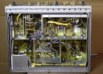
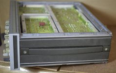
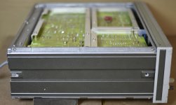
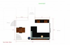
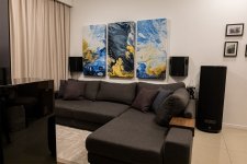
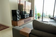
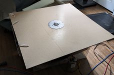
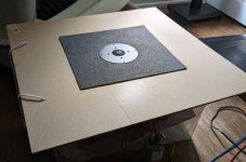
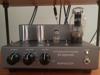
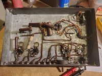
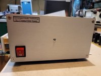
Being working on this project for the last two years. Here the final result, working perfectly.

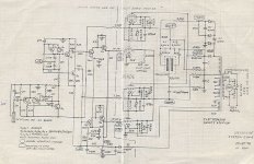
This project started when one of my friend brought me a defective SL1 (original), he said: <nothing serious, just a little noise at the output, probably a noisy tube...>, one month later it was fixed, nothing serious, yeah right... When I started to work on the unit at first I was completly lost, it was a very complex preamp, with a lot of SS parts near the tubes, very complex HV regulator section, and external power supply. I rapidly realized that the supply was defective, and that probably some other parts, these small TO92 SS parts were gone as well. I had no schematics, they were impossible to get, I was left in the dark.

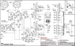
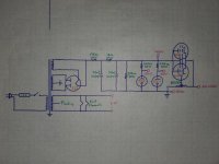
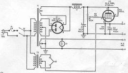
I said to my friend I can try to fix it, but it will be expensive, and will take me a long time (doing repair part time, was still working at the time). First I needed to repair the HV section, all the heaters supplies seems ok. I started to trace the HF regs section schematic, it was a mess, even worst, some part of it was inside the external supply. I worked, and worked, and finally got something that make sense. I isolated this section, and found all the defective parts, replaced them, and got a working HV regs. Then using an external lab power supply (current limited), and by isolating each tubes section, found the shorted/open SS parts driving the tubes (then are small MOSFET), and replaced all the defective ones, tracing the schematic while I go.

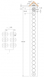
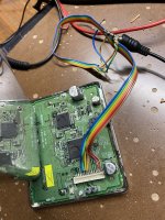
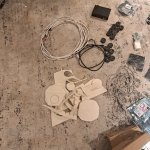
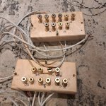
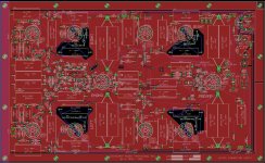
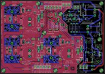
While doing the schematics, it was difficult to trace the PCB, and to see where all the traces were going, so to help me I started making a PCB, to help tracing, and figuring the schematics. When I was done I had a pretty close PCB, probably with some errors, but enough to complete my schematics and the repair.

We listend to the repaired unit and we found it was one of the best preamp we ever listened to, period. And the phono section is just gourgeous. A real reference preamp...

A few years later an other friend ask me for a recommadation for his system (he has a Pass XA30.8 as amp). He was looking for a good preamp, and a phono preamp. I told him that the CAT SL1 was doing all that, in one package. I bought a used unit from Alberta, but guess what it was intermittent. I had to repaired this one two. It has a few problem, intermittent tube sockets, and a few cold junction soldering. Repalced all the sockets, and redo the solder joint and it was ok. This unit was slightly newer than the the first one I repaired, version MKII. I used my previous info for the repair, fine tuned my schematics and PCB layout, and did the few new changes.

Then finally I had to repair a third one, this one had a severe problem. The power supply main transformer has the HV secondary burned, litterally detroyed, and the rest of the HV section gone naturally. One very bad short coming of this preamp supply is this, the main fuse will let go if one of the high current heater supply short, but won't blow if it is only the much smaller current HV section. The HV really needs its separate low rating fuse.

I was pretty close the first time, and I was confident I had the real thing. During COVID I had spare time and decided to make myself a CAT SL1, my own version. To improve on the thing I don't like about the originals I worked on I decided to make these changes:

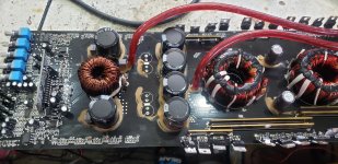
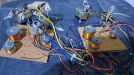
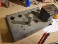
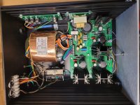
-Better made external power supply, with larger enclosure, proper layout, bigger regulator heatsinks, CRC filtering and better caps on the HV section, Separate fuses on all the outputs (Heaters and HV), and since I want SE/BAL converters in the preamp, extra +/-24V supply for these converters.
-I hate the original cable between the supply and preamp. It can't be disconnected, it is large gauge, not very good quality ( at least on the ones I saw), make working on the preamp difficult, etc... So I want a flexible cable, with detachable connector at the preamp. I know, it may not sound as good as the fixed one, but no way I'll have a captive cable on my preamp...
-Added a ground breaker to the supply, my own version of the Ayre noise filter and Furutech IEC AC inlet connector.
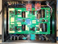
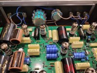
-The original used the excellent, and now gone REL-Caps everywhere (the new one have custom made caps). I cannot get REL-Caps, so used more mondain IC film caps for the supply, and Mundorf caps for coupling. For the output I went over the board with Mundorf Supreme Silver/Gold/Oil caps, bypassed with Duelund copper foil.
-The original has the excellent ROE resista resistors. One of my friend was able to give my most of the values I needed. Used a mix of Tantalum and Shinkoh and Kiwame resistors for the rest.
-The original used for volume an Electroswitch 24 steps attenuator with ROE descrete resistors. Again impossible to get, found a 4 decks one on ebay. Mounted all the ROE resistors, ans it tested fine.
-The Balance used a smart way of doing the balance without impacting on the channel crosstalk. It adds resistors on the lowering channel, in fact increasing these channel volume total value, decreasing the actual volume, while the other channel don't move, clever. Again it is using an Electroswitch rotary switch, got this one at Mouser...
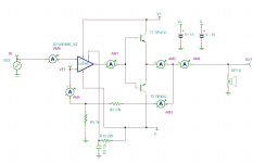
-I made a few years back small SE/BAL and BAL/SE converter PCB, using the mostly transparent DRV134 and INA2134 chips. I installed them inside the preamp. The SE/BAL input converter is only on the CH1 input, with a switch to select between RCA and XLR. The SE/BAL output converter is at the output. Since this preamp can produce HUGE output level, I installed +/-12V protection zener at the input, in fact limiting the preamp to +/-12Vpk-pk output. If the preamp is so good I may install Lundhall balanced output down the road...
-The MK2 version I saw use Cardas hook-up wiring, I used the same.

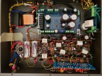
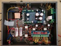
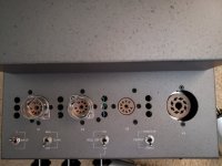
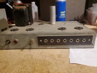
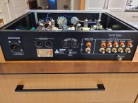
So, here my preamp, after all this work I'm very happy with the result, no noise, phono section has a perfect RIAA curve after some tuning, same gain on both channels with the tubes I used, very stable HV supply with no noise. Yes I used a clone enclosure from China but I remade completly the rear panel, and trashed the included cheap toggle switches, bought good quality C&K ones.

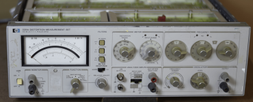
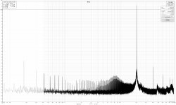
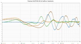
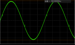
Here a few measurements:
Preamp Section gain: 25.5dB, BW 836Khz, Vout max 50Vac (limited now by the SE/BAL converter inout zener at +-12Vpk-pk), THD: 0.01%, noise <1.2mvac, Zout around 500 ohms.
Phono section gain: 45dB with external load connector. Huge overload threshold. My friend use it with a Denon DL103 without problem...

Attachments

  • 20230705_193006.jpg
    20230705_193006.jpg
    129.5 KB · Views: 566
  • Supply_s.jpg
    Supply_s.jpg
    232.8 KB · Views: 589
  • 20230810_205316_s.jpg
    20230810_205316_s.jpg
    303.4 KB · Views: 634
  • 20230810_180401_s.jpg
    20230810_180401_s.jpg
    257.1 KB · Views: 745
  • 20230810_180449_s.jpg
    20230810_180449_s.jpg
    186.2 KB · Views: 603
  • Main PCB_s.JPG
    Main PCB_s.JPG
    225.5 KB · Views: 564
  • Psu pcb_s.jpg
    Psu pcb_s.jpg
    283.9 KB · Views: 609
Projects by fanatics, for fanatics
Get answers and advice for everyone wanting to learn the art of audio.
Join the Community
507,660
Members
7,883,033
Messages

Filter

Forum Statistics

Threads
405,973
Messages
7,883,033
Members
507,660
Latest member
AlvianSuryaAudio