Hi All,
In the last few months build three attenuators.
First i built a 1/10th power 1/2 volume attenuator from Rob Robinette’s site 1/10 power switch.
(For 16ohm speaker 32r and 24r were used)

Here is the first attenuator i built

This drops a significant amount of volume but not enough for a 3-4 watt amp running on full tilt.
So I build a second one to place in series and get 1/100 power or 1/4 volume.

The resistors were 33r / 5watts and ( 49 || 49 ) for 24.5r / 10watts.
While the box is very small, it should be ok for a couple of watts overdriven and is safe to use positioned second in line ( closes to the speaker) for the amps I’m using.
This combination was used for a while, though i began to wonder if i too there was a need for a bright switch of some kind.
The third i have built after reading the following threads.
Attenuator for a 15W to 25W guitar amp and Cabinet design for 5" driver - guitar use
So i built a FAHEY Simple Attenuator, however with 16r as R1, 940r as R2 and 39r as R3 of the T pad, with true-bypass switching.
This results in conversation level volumes with a 10” speaker and 3-4 watt amp at full tilt and exceedingly quiet volumes for clean tones.


I use this attenuator on its own , and am impressed with the tone as well as the volume reduction.
It is brighter in the top end, than either of the other two attenuators individually or in series.
So with this in mind i played around with first adding a 18r on a lead plugged into the first 1/10th power attenuator.
This I understand would effectively make the circuit a T- Pad
Without the 18r in series it was less attenuated and more ‘full range’ / flatter sounding, not bright but consistent and clear.
With the 18r in series the tone was more attenuated and slightly high-mid range focused and ultimately more like the unattenuated amp but quieter.
This seems consistent with the posts in the linked topics above.
So i decided to hardwire 18r and have a switch to bypass it to give a choice of attenuation level and tonality.
The difference would not be dramatic but each flavour had its own character, one more suited to super clean and the other to different degrees of breakup and overdrive.

However and this is the surprising part for me, when ‘bypassing’ the 18r, attenuation level is less but the tonality is the same as with the 18r ‘unbypassed’.
I tested the second 1/10th attenuator which i had not modified to make sure I wasn’t imagining anything, and sure enough the ‘standard’ 1/10 power attenuator had the full-range/flat like tonality.
Now I'm wondering, how, why or if the 18r when bypassed in the sense of ‘path of least resistance’, still plays ‘active’ part in the circuit?
This is not necessarily a bad thing, and may even allow for more tonal choices, with different values of r3, either in bypass or in ‘true bypass’.
(It is likely though that there will only be so many ‘useful differences’ and perhaps one or perhaps two switchable levels or tones combinations.)
So before I rewire this first attenuator again, this time to true-bypass the 18r to see what happens please let me know your thoughts and reasons for what i’m hearing.
While i recognise this may be subjective, please enlighten me to how what im hearing may occur in the circuit.
Cheers
CrazyNutter
In the last few months build three attenuators.
First i built a 1/10th power 1/2 volume attenuator from Rob Robinette’s site 1/10 power switch.
(For 16ohm speaker 32r and 24r were used)
Here is the first attenuator i built
This drops a significant amount of volume but not enough for a 3-4 watt amp running on full tilt.
So I build a second one to place in series and get 1/100 power or 1/4 volume.
The resistors were 33r / 5watts and ( 49 || 49 ) for 24.5r / 10watts.
While the box is very small, it should be ok for a couple of watts overdriven and is safe to use positioned second in line ( closes to the speaker) for the amps I’m using.
This combination was used for a while, though i began to wonder if i too there was a need for a bright switch of some kind.
The third i have built after reading the following threads.
Attenuator for a 15W to 25W guitar amp and Cabinet design for 5" driver - guitar use
So i built a FAHEY Simple Attenuator, however with 16r as R1, 940r as R2 and 39r as R3 of the T pad, with true-bypass switching.
This results in conversation level volumes with a 10” speaker and 3-4 watt amp at full tilt and exceedingly quiet volumes for clean tones.
I use this attenuator on its own , and am impressed with the tone as well as the volume reduction.
It is brighter in the top end, than either of the other two attenuators individually or in series.
So with this in mind i played around with first adding a 18r on a lead plugged into the first 1/10th power attenuator.
This I understand would effectively make the circuit a T- Pad
Without the 18r in series it was less attenuated and more ‘full range’ / flatter sounding, not bright but consistent and clear.
With the 18r in series the tone was more attenuated and slightly high-mid range focused and ultimately more like the unattenuated amp but quieter.
This seems consistent with the posts in the linked topics above.
So i decided to hardwire 18r and have a switch to bypass it to give a choice of attenuation level and tonality.
The difference would not be dramatic but each flavour had its own character, one more suited to super clean and the other to different degrees of breakup and overdrive.
However and this is the surprising part for me, when ‘bypassing’ the 18r, attenuation level is less but the tonality is the same as with the 18r ‘unbypassed’.
I tested the second 1/10th attenuator which i had not modified to make sure I wasn’t imagining anything, and sure enough the ‘standard’ 1/10 power attenuator had the full-range/flat like tonality.
Now I'm wondering, how, why or if the 18r when bypassed in the sense of ‘path of least resistance’, still plays ‘active’ part in the circuit?
This is not necessarily a bad thing, and may even allow for more tonal choices, with different values of r3, either in bypass or in ‘true bypass’.
(It is likely though that there will only be so many ‘useful differences’ and perhaps one or perhaps two switchable levels or tones combinations.)
So before I rewire this first attenuator again, this time to true-bypass the 18r to see what happens please let me know your thoughts and reasons for what i’m hearing.
While i recognise this may be subjective, please enlighten me to how what im hearing may occur in the circuit.
Cheers
CrazyNutter
It will certainly make the attenuator into a T-pad. But it's the wrong sort of T-pad. The amplifier will "see" a load of (18+8) ohms, i.e., a 26 ohm load....i played around with first adding a 18r on a lead plugged into the first 1/10th power attenuator...
This I understand would effectively make the circuit a T- Pad
This is a pretty bad mismatch for a (valve) guitar amplifier designed to drive an 8 ohm speaker.
We know that if the load mismatch is bad enough, and you drive the amplifier hard, it can fry the output transformer and/or output valve.
I don't know if you are about to fry your amp or not - but 26 ohms instead of 8 is a bad mismatch, and bad things might happen.
Personally, I would not take the chance, if it was a guitar amplifier I liked.
If you do the math, Robinette's attenuator does not have this problem - it always presents an 8 ohm load to the guitar amplifier.
Fahey's 3-resistor attenuator doesn't have the problem either. If you choose the resistors as he indicates, the amplifier "sees" something very close to the proper 8 ohms. It is a simple and ingenious solution to the attenuator problem.
If that is correct, then you have proved to yourself that the 18 ohm series resistor does not actually do anything useful to the tone. It also puts your guitar amplifier at risk, because of the load mismatch....However and this is the surprising part for me, when ‘bypassing’ the 18r, attenuation level is less but the tonality is the same as with the 18r ‘unbypassed’.
If you've wired the bypass switch properly (i.e. it puts a short-circuit right across that series 18 ohm resistor in the "bypass" position), then that resistor cannot play any kind of role in the circuit when bypassed....how, why or if the 18r when bypassed in the sense of ‘path of least resistance’, still plays ‘active’ part in the circuit?
But when you flip the switch to the "not bypassed" position, you raise the amplifier load to 26 ohms, putting your amplifier at risk.
Can you draw a schematic showing what you mean by "bypass" vs "true bypass" in this case, so I can understand what you're actually planning to do?So before I rewire this first attenuator again, this time to true-bypass the 18r to see what happens
Once again: inserting an extra 18 ohms in series is not a good idea for the health of the amplifier.
-Gnobuddy
Hi Gnobuddy,
Thanks for your reply, I certainly don’t want to damage my amp.
The amp is a expects a 16 ohm load and I’m using a 16 ohm speaker.
I did measure the resistance of the attenuator on its own and then with a 16 ohm speaker plugged in.
With nothing plugged into the attenuator it measures 24.7 ohm.
With a 16 ohm speaker plugged in the total resistance measures 16.7 ohms.
The speaker on its own measures 13.6 ohms.
Even though I have measure 16.7 ohms at the input to the attenuator with the speaker attached does the amplifier see a different load?
Perhaps i have wired it differently to Rob Robinette circuit unintentionally.
You can see the picture of how its wired in the last picture.
I will recheck it and post a circuit of what i have wired later on today.
Thanks for your reply, I certainly don’t want to damage my amp.
It will certainly make the attenuator into a T-pad. But it's the wrong sort of T-pad. The amplifier will "see" a load of (18+8) ohms, i.e., a 26 ohm load.
This is a pretty bad mismatch for a (valve) guitar amplifier designed to drive an 8 ohm speaker.
The amp is a expects a 16 ohm load and I’m using a 16 ohm speaker.
I did measure the resistance of the attenuator on its own and then with a 16 ohm speaker plugged in.
With nothing plugged into the attenuator it measures 24.7 ohm.
With a 16 ohm speaker plugged in the total resistance measures 16.7 ohms.
The speaker on its own measures 13.6 ohms.
Even though I have measure 16.7 ohms at the input to the attenuator with the speaker attached does the amplifier see a different load?
Perhaps i have wired it differently to Rob Robinette circuit unintentionally.
You can see the picture of how its wired in the last picture.
I will recheck it and post a circuit of what i have wired later on today.
I've traced the circuit that as wired in the last picture.

Which is not how I had meant to wire it, though it look like also did this on my first revision without the 18 ohm (or switch).
So with the 18 ohm not by passed the load to the amp as is would be 32+18+16 || 24 = 16.8 ohms
with 18 oms switched out 48 || 24 = 16 ohms
When the attenuator was supposed to be off the load would be 16 ohms or 34 ohms.
So not a good condition with the 18 ohm not bypassed.
That said it seamed to work well before I added the 18 ohm
Looking at the text and the schematic on Rob Robinette's site the switch is wired oppositely from the way i have wired it.
However he states that his 1/4 power switch ( and hence 1/10th power switch) are based on the Fender Eric Clayton Tremolux.
This Topic on EL34 forums shows the switch wired opposite to Robs wiring, such that when the circuit is engaged the resistor to ground comes before the resistor ins series with the speaker.
https://el34world.com/Forum/index.php?topic=21535.0

its late and i'm getting confused which is the correct or most appropriate way to wire it.
As Robs would seem to be a Lpad / voltage divider and my wiring and the EC if the schem is correct is not an Lpad
so ive found this link and going to see what makes sense to me when i'm less tired.
https://www.electronics-tutorials.ws/attenuators/l-pad-attenuator.html
Thanks again @Gnobuddy for pointing out that i could possibly damage the amp with the 18 ohm in series
-CrazyNutter
Which is not how I had meant to wire it, though it look like also did this on my first revision without the 18 ohm (or switch).
So with the 18 ohm not by passed the load to the amp as is would be 32+18+16 || 24 = 16.8 ohms
with 18 oms switched out 48 || 24 = 16 ohms
When the attenuator was supposed to be off the load would be 16 ohms or 34 ohms.
So not a good condition with the 18 ohm not bypassed.
That said it seamed to work well before I added the 18 ohm
Looking at the text and the schematic on Rob Robinette's site the switch is wired oppositely from the way i have wired it.
However he states that his 1/4 power switch ( and hence 1/10th power switch) are based on the Fender Eric Clayton Tremolux.
This Topic on EL34 forums shows the switch wired opposite to Robs wiring, such that when the circuit is engaged the resistor to ground comes before the resistor ins series with the speaker.
https://el34world.com/Forum/index.php?topic=21535.0
its late and i'm getting confused which is the correct or most appropriate way to wire it.
As Robs would seem to be a Lpad / voltage divider and my wiring and the EC if the schem is correct is not an Lpad
so ive found this link and going to see what makes sense to me when i'm less tired.
https://www.electronics-tutorials.ws/attenuators/l-pad-attenuator.html
Thanks again @Gnobuddy for pointing out that i could possibly damage the amp with the 18 ohm in series
-CrazyNutter
Rob Rob's designs are very good , and you can stack several did to end. They will preserve tone quite well for a passive resistive attenuator. If you'd like to go further, check out ours on the Marshall forum:
https://www.marshallforum.com/threads/simple-attenuators-design-and-testing.98285/
It's based on similar principles, but reactive and multi-stage. It's written up as a DIY project and many have been built
https://www.marshallforum.com/threads/simple-attenuators-design-and-testing.98285/
It's based on similar principles, but reactive and multi-stage. It's written up as a DIY project and many have been built
Hi JohnDH,
Thanks for your reply.
Yes, I believe they are. However the circuit diagram is not clear to me which way the switching is happening.
After tracing the picture he has for building the circuit on the output jacks of an amp, it seems like, his circuit is not an Lpad and is the same as the EC Tremolux circuit.
I think I was assuming his wiring was an Lpad and i got thinking i could add the extra leg to make a Tpad. So I got confused over terms when I had wired it correctly in the form of Rob Rob / EC in first place.
I think I have learned something in the process. Will take a good look at the link you posted and likely then learn a great deal more!
Thanks for your reply.
Rob Rob's designs are very good , and you can stack several did to end. They will preserve tone quite well for a passive resistive attenuator. If you'd like to go further, check out ours on the Marshall forum:
Yes, I believe they are. However the circuit diagram is not clear to me which way the switching is happening.
After tracing the picture he has for building the circuit on the output jacks of an amp, it seems like, his circuit is not an Lpad and is the same as the EC Tremolux circuit.
I think I was assuming his wiring was an Lpad and i got thinking i could add the extra leg to make a Tpad. So I got confused over terms when I had wired it correctly in the form of Rob Rob / EC in first place.
I think I have learned something in the process. Will take a good look at the link you posted and likely then learn a great deal more!
Hi JohnDH,
A few quick questions about your “reverse Lpad” building block. I understand this to be a T-pad with zero leading resistor from another of your threads on this forum.
This you state is ok if the attenuation is say up to 7db.
Elsewhere you talk about the having the speaker see an output impedance of about 20 ohms for a 8 ohm speaker (2 - 2.5x nominal impedance).
Do you have a way to calculate different values for this block for different attenuation db and speaker loads?
When does it start being necessary to include a leading resistor of a T-pad ?
How do you estimate or calculate the output impedance of an tube amp?
Does the stage 2 of your M2 design for a 16 ohm output has 20 ohm source resistance ?
Should it be 32 -40 ohm if that block were to be used on its own?
How do you there calculate R2 ? Like this R1 + Speaker ohms || R2 = approx expected speaker load
Hope you can point me in the right direction to understand these questions.
-CrazyNutter
I can answer some of those!
So, typically, to get a given attenuation with a given input impedance, and a different output impedance, you need 3 resistors. And with the values I use, at about -7db, the leading one of a T gets to zero.
In my base design, I have an always-on first stage, which also includes an inductor. This stage dominates what the amp sees. So for following stages, I can let the input impedance of each stage drift away from the target, since Stage 1 will correct it, and so I just make sure output impedance is on target, ie what the amp sees.
The whole maths is simple at each stage but gets complex when you combine multiple stages. Also literally, because the analysis to include the coil, plus the speaker requires consideration of phase and complex-number maths. It was a good learning exercise to remember that from school!
The output impedance of a tube amp can't be measured with a meter, but is derived. It depends on the output circuit and also on negative feedback in the power stage. It also changes as the amp is driven, but the key values for my design are based around small signals, ie clean. What you do is send a constant signal into a resistive load and measure the output voltage. Then change the load to a different Ohms and repeat. Then it's algebra.
CN, there is a difficult and complicated way, but fortunately, these days there is also a relatively easy way.<big snip>
Do you have a way to calculate different values for this block for different attenuation db and speaker loads?
When does it start being necessary to include a leading resistor of a T-pad ?
</snip>
[/code]
The hard way is to learn a handful of electrical theorems, how to represent inductances and capacitances using complex numbers, and how to solve systems of simultaneous complex-number equations using matrices.
This stuff is typically taught in first-year college mathematics for engineering students. It gives smart students with an aptitude for mathematics lots of headaches and sleepless nights. Other students, lacking those particular aptitudes, may never get it. It's difficult, complicated, abstract stuff, and definitely not for everyone.
The much easier way is to download and install (free, no cost) LTSpice ( https://www.analog.com/en/design-center/design-tools-and-calculators/ltspice-simulator.html ), or another similar free circuit simulation software, and learn how to use it.
There is a learning curve here as well, but once you figure out how to use the software, you can use it to quickly simulate complicated circuits - circuits that would take hours or days of algebra if you tried to solve them by hand with pencil and paper.
There are some very well-done and helpful LTSpice tutorials by Simon Bramble here: http://www.simonbramble.co.uk/lt_spice/ltspice_lt_spice.htm
I'm attaching a screenshot showing an LTSpice simulation of a little guitar attenuator I built a few years ago. It uses a 10-ohm wirewound pot (sometimes called a rheostat), with a 39 ohm resistor connected to the wiper. The (tube) guitar amp feeds the two ends of the pot, while the 8-ohm guitar speaker goes between the far end of the 39 ohm resistor and ground.
This particular attenuator has no inductors or capacitors in it, so it behaves very nearly like a pure resistor (no changes with frequency) as far as the amplifier is concerned. (The speaker itself does have an impedance which changes with frequency, but very little of that gets back to the amp through the 39 ohm resistor.)
In the pink ellipse near the top right of the plot, you can see that I told LTSpice to calculate (amplifier output voltage)/(amplifier output current). This ratio tells you the load that the amplifier is seeing.
This equation is plotted as the bright red line. It is flat, straight, and constant - doesn't vary with frequency - because there are no inductors or caps in this circuit.
If you look along the left edge of the graph, you can see the second pink ellipse showing the actual value (ohms) of this load. It is between 8 ohms and 9 ohms. In fact, it is only a smidgeon more than 8 ohms. The amplifier won't have any trouble driving this attenuator, because it will "see" a nearly-perfect 8 ohm load, no matter where I set the 10-ohm pot.
Meantime, the speaker will "see" about 40 - 50 ohms, as though it was driven from an amplifier with that high a source impedance. This is key to preserving the original frequency response of the amplifier, i.e. the tone won't be changed when the attenuator is added.
I have not shown how this latter number can be calculated. But you can have LTSpice work this out for you, as well. (I worked it out the "hard way" in this case, but LTSpice will do it for you very easily.)
One way to estimate the output impedance is to look at the output valve (tube) datasheet curves, work out the slope of the anode curves (change in volts / change in amps), and divide that answer down by the output transformers winding ratio.How do you estimate or calculate the output impedance of an tube amp?
I've done this calculation in the past, and typical answers were anywhere between 50 ohms and 150 ohms, depending on the amplifier. None of the answers will be exact, they will only give you a ballpark value, because there are so many unknowns. (For example, changing the screen grid voltage will alter the anode curves - but the datasheet only gives curves at specific grid voltages, which often don't match the actual grid voltage in your amp.)
If the amplifier includes negative feedback (many do, including all classic Fender valve guitar amps), that will additionally lower the output impedance, by roughly a factor of two or three.
Measuring the output impedance (rather than calculating it) will get rid of some of these unknowns, but it also adds some new unknowns. To measure, you have to feed the amplifier input with a steady sine wave signal at, say, 300 Hz, then precisely measure the output voltage across two different load impedances, one at a time. For example, if you have an amplifier designed for an 8 ohm speaker, you could do the test first with an 8 ohm load, then with a 4 ohm load (a mismatch, but unlikely to hurt your amp because it's lower than 8 ohms, which is generally safer for a valve amp.)
As you can imagine, if the amplifier has a higher output impedance, then its output voltage will drop more when you switch from the 8 ohm load to the 4 ohm one. (The output voltage drops for the same reason your car headlights dim when you crank the engine.)
So if you measure the two voltages, you can use a little algebra to calculate the amplifier's output impedance.
However, I don't think there's a need to actually do this. Several people have already made these measurements, including Printer2 (diyAudio member) and JohnDH. The rest of us can benefit from their hard work, and don't have to risk our amplifiers by making these measurements. IIRC, typical answers vary from 20 ohms to 50 ohms.
-Gnobuddy
Attachments
Hello! (First post but have lurked here for years)
Reviving this because I also was thinking about building a simple attenuator. I could just buy one I suppose, but I also want to understand better.
I'm a long-time audio engineer so I have a lot of practical knowledge, but not much real electronics knowledge (trying to fix that). I can root around in an amp and find something that melted and solder a new one in, and I can wire a two way switch in a house. So that's kinda where I'm at. I'm reading 'The Art of Electronics' and trying to learn more theory.
I didn't predict that putting a resistor (or two) between an amp and a speaker would be over my head, but I guess it is.
There must be some really basic fundamentals I don't understand, because the original Rob Robinette 1/10th power thingy (with the switch closed)
Looks like this as far as I can tell:

Isn't that like a backwards voltage divider?
I don't understand why it is not like this which would be more like what's in the textbook:

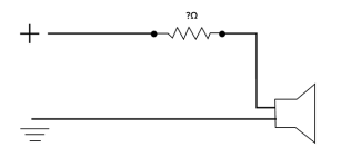
Or even just like this, why not just this?:

What am I missing here?
Reviving this because I also was thinking about building a simple attenuator. I could just buy one I suppose, but I also want to understand better.
I'm a long-time audio engineer so I have a lot of practical knowledge, but not much real electronics knowledge (trying to fix that). I can root around in an amp and find something that melted and solder a new one in, and I can wire a two way switch in a house. So that's kinda where I'm at. I'm reading 'The Art of Electronics' and trying to learn more theory.
I didn't predict that putting a resistor (or two) between an amp and a speaker would be over my head, but I guess it is.
There must be some really basic fundamentals I don't understand, because the original Rob Robinette 1/10th power thingy (with the switch closed)
Looks like this as far as I can tell:
Isn't that like a backwards voltage divider?
I don't understand why it is not like this which would be more like what's in the textbook:
Or even just like this, why not just this?:
What am I missing here?
Attachments

None of these circuits is inherently right or wrong. You want to make the amplifier have a certain amount of distortion,
but still load the amplifier properly so that it does not fail. Whichever circuit does that for you is the right circuit, for you.
First you have to find out what it is that you want.
but still load the amplifier properly so that it does not fail. Whichever circuit does that for you is the right circuit, for you.
First you have to find out what it is that you want.
It takes time to just learn how to visualize this stuff. So again apologies for my noob questions.
To propose an answer to the first part of my own question though. I guess just rearranging it these are really the same thing aren't they?


To propose an answer to the first part of my own question though. I guess just rearranging it these are really the same thing aren't they?
Am I correct that the load seen by the amp in the original design would be 20.8 ohms?
(12*8 / 12+8) + 16
(12*8 / 12+8) + 16
Found a good article explaining the basics:
https://www.emprizeamps.com/post_attenuators.html
Makes more sense now, thanks!
https://www.emprizeamps.com/post_attenuators.html
Makes more sense now, thanks!
You should include the schematic in your post with a question about it. There have been too many schematics.Am I correct that the load seen by the amp in the original design would be 20.8 ohms?
(12*8 / 12+8) + 16
Amplifier loading:
with the switch up ------ just the speaker, 8 ohms
with the switch down ------- 12 // ( 16 + 8 ) which also equals 8 ohms
with the switch down, the speaker attenuation is 8 / (16 + 8 ) which equals 1/3 or about -10dB
which is about half as loud
However, this is a very bad circuit, because with no speaker plugged in, and with the switch in the up position,
the amplifier is SHORTED OUT.
Last edited:
Wow, this is really hard for me for some reason...
(Organic Chemistry, which I actually loved, was the most difficult class I ever took.
But, after much consternation, once it sunk in, it seemed easy!)
Anyway thanks for your patience, hopefully this will help another noob someday.
Good call on the short, but just so I understand this VERY simple circuit (duh) even if I don't want to build it:
I think I get it, and the reason it works out to be 8 ohms is because you just add the speaker and the resistor in series with it together so this:

is actually the same as this, right?:

(Organic Chemistry, which I actually loved, was the most difficult class I ever took.
But, after much consternation, once it sunk in, it seemed easy!)
Anyway thanks for your patience, hopefully this will help another noob someday.
Good call on the short, but just so I understand this VERY simple circuit (duh) even if I don't want to build it:
I think I get it, and the reason it works out to be 8 ohms is because you just add the speaker and the resistor in series with it together so this:
is actually the same as this, right?:
- Home
- Live Sound
- Instruments and Amps
- Attenuators: T-Pads, level and tonality