Adventures in MTMW land

Here’s my latest excursion, 2x SB13PFC, (great detail yet full bodied sound)​

Vifa NE25VTS-04 – love the liveliness of these non ferrofluid tweeters,

and an old pair of 10” Peerless 850146 solidly filling in the low end.

Xovers are quasi series 2nd order, simply because that led to more economical parts than parallel,

box is laminated Okume, it was cheaper than ply when I went to the hardware store, & looks a lot better. These will be mains in my HT system.

Attachments

  • MTMWs.jpg
    MTMWs.jpg
    572.1 KB · Views: 98

7 Years went under the bridge – Getting close to soldering.

It has been a long haul. Same old story of a plan to build speakers that turns into years… I would do it all over again. Long story short, I have tried many drivers and many many crossover schemes and it’s at a point where it’s the best I think I can do given that I’m locked into these drivers. In the next 8 days I will make a last-ditch effort to try some suggestions or just tweak to taste. After that I’m going to solder it up and finally clean up my listening room and get on with my life… I don’t really want to move too far away from the XO I have because it sounds so good but if anyone has any suggestions, I’m open. (I have no desire to drive these speakers with tubes by the way) Also, the cabinet is what it is. I can mess with the ports and fill but everything else is set. I’ll get pics of them out when they’re finished.


My system:

Computer (ASUS mobo, LGA-1700 I3 cpu, Matrix element-H USB out) based Jriver CD collection and Apple Music streaming out to

Simaudio 280D dac out to

Gustard P26 preamp XLR and SE out to

Parasound JC5 (in XLR) to drive the 12”, 8” 4” and Tweeter.

Neurochrome Universal Buffer (SE) to level match the other drivers out to

ICEpower 1200AS1 class D mono to drive the 15”


The drivers in this order from the top of the speaker down to the floor:

ETON 12-212/C8/62 HEX SYMPHONY II (quasi-rear ported but heavily filled with wool (cabinet and port))

Scanspeak 12MU/4731T-00 (large sealed area for a 4”)

Scanspeak ellipticor D3404/5520-00 tweeter

B&C 8MBX51 (average size sealed area mostly filled with wool)

SB acoustics SB42FHCL75-6 (Large front ported cabinet moderately filled with wool (cabinet and port))


The FR of each driver was taken with a Behringer ECM8000 test mic at 15mm from driver into a Mackie Blackbird interface using REW out to the 208D dac. I had to do the FR test sweeps at a lower level to avoid the phase giving an incorrect reading. I’m not sure if it’s the interface or the mic but at loud levels up close things get inconsistent. All the impedance sweeps were done in their cabinets with the DATS-v3. For the VCAD screenshots, all 5 drivers are not driven by one amp. I show it that way to get an idea of what the whole system is doing together. Also, I’m not sure if the FR above 14K drops because of my computer or what. I’ve tested two other dacs and another set of tweeters and they all do the same thing.

Attachments

  • drivers.jpg
    drivers.jpg
    71.3 KB · Views: 143
  • V11 all drivers.png
    V11 all drivers.png
    133.4 KB · Views: 135
  • V11 no sub.png
    V11 no sub.png
    138.3 KB · Views: 137

B&C U12

I'm considering building a U12, designs available from B&C, with the dedicated passive crossover FBU128.
Now I'm not a fan of Titanium diaphragms and would like to replace the suggested DE780 compression driver with something else.
AudioXpress tested the driver and you can see 3.66ms long streaks in the waterfall plot around 14kHz - that won't work for my taste.
Now my question is, can I still utilize the FBU128 crossover when using another compression driver under certain considerations?

For example I'm looking at a Beyma CD14ND.
Obviously this driver would have to have the same impedance as the DE780. But when I look at both the DE780 and CD14ND impedance curves, they differ naturally along different frequencies. Or any driver for that matter. If at all, how much of an effect can this have on the end result of a targeted flat response? Also, does the power rating of the driver have an effect as well, other than me having to rebalance the outputs of the two drivers in the box.
I'm going to use a nice Pro amplifier with quite some DSPing available.

I'm also open to suggestions for other compression drivers (budget is up to $250). Also considering BMS 4554 (even though crossover to high for this one probably) , FaitalPro HF146,...

I'm a bit new to passive xovers, so far I used actives only. I hope my questions are not too naive.
Thanks!

SAE XXX Preamp problem

I was given a SAE XXX preamp that for some reason had the balance slider pot removed and then put the unit back together. I would have been happier If they had at least bypassed the pot entirely. But no they just pulled it as shown in photo. I did locate a 100k ohm MN taper from surplusdealusa with the correct number of pins. No way to identify the pins on the new one even though the pin out configuration on the new matched the schematic and circuit board. The top two pins on the pot are identified as "3" and second row (staggard) of two pins are identified as "1" and the bottom two say "2". No mention of any ground. Any ideas how I can install the pot correctly. Have attached photos of schematic, new pot and the actual circuit board showing the holes were it was. Is this a straight plug-in or are modifications required? If this pot is a no go any ideas how to bypass the pot completely? Help appreciated.

Attachments

  • DSC07344.JPG
    DSC07344.JPG
    395.7 KB · Views: 206
  • DSC07345.JPG
    DSC07345.JPG
    287.7 KB · Views: 187
  • DSC07346.JPG
    DSC07346.JPG
    930.5 KB · Views: 197

criterion for I/V selection

Hi everyone .
the choice for the I/V stage of the DAC is not easy (perhaps it is easier for those with OPAMP than discretes ) . how is it best to deal with it? which criteria to adopt? .
understanding what are the problems affecting the output signal and choosing an I/V that solves them, even if not completely, is this the best way? . admitted to being able to understand what the circuit can do, after having identified it (many times we start from the description by whoever designed the circuit).
I also assume that multibit DACs have different problems than DS ones

Vintage Mission Cyrus ONE (or TWO) vs. currently available Cyrus ONE - which provide better Audio ?

For most hifi dealers the answer is clear: new is better than old in general.
If perform listening tests there between both versions, I note in most cases, that the old version is in working but no refurbished condition (i. e. with the old elcap stuff); then of course the hifi dealer is right
I haven't heard the new version but from the old vintage version I know the sonic character good (due repair service) and sound is very good in all respects (after refurbishing of course) - at least for my ears.
According the images of PCB from new version (have a look to the attached photos) I can't believe, that using of such cheap capacitors in the power supply does provide such a good sound character as mentioned under
https://www.whathifi.com/features/old-amplifier-vs-new-amplifier-which-is-better

What experiences are to note in general while compare both versions in listening tests ?
Thank you very much for comments.

some additional URL's - vintage version:
http://www.wiredwood.co.uk/wordpress/mission-cyrus-one-amplifier-a-look-inside/
https://ftbw.de/xp/amplifier-xp/cyrus1-black-02.html
https://www.stereophile.com/content/mission-system
- and new version
https://www.ecoustics.com/reviews/cyrus-one-hd-integrated-amplifier/
https://hifi-ifas.de/test-cyrus-one-hd-vollverstaerker-mit-usb-dac
https://www.whathifi.com/cyrus/one-hd/review

Attachments

  • Cyrus-ONE-inside_big-1100x1100.jpg
    Cyrus-ONE-inside_big-1100x1100.jpg
    118.3 KB · Views: 344
  • cyrus-one-hd-internal.jpg
    cyrus-one-hd-internal.jpg
    94.5 KB · Views: 230
  • cyrus-one-hd-internal-closeup.jpg
    cyrus-one-hd-internal-closeup.jpg
    86.5 KB · Views: 203
  • Cyrus One new-open.jpg
    Cyrus One new-open.jpg
    331.6 KB · Views: 250
  • Clean_Top_view_Cyrus_OneHD.jpg
    Clean_Top_view_Cyrus_OneHD.jpg
    258.5 KB · Views: 222
  • Cyrus-One.old version.jpg
    Cyrus-One.old version.jpg
    475 KB · Views: 316

Which Head Shell?

Hello - this post is a little similar to one that I've recently posted about cartridge mounting on AT MG9 and S8 head shells, but is dealing wore specifically with the difference between these two head shells with regard to resonance. I currently have the Audio-Technica MG9 head shell which has an odd 'melted' look on its top, which I've noticed in photos elsewhere - quite odd and unattractive (see photo 1). I have just ordered the Audio-Technica S8 head shell which, to my eyes, is much nicer looking (see photo 2), but... am I making a mistake here? Should I instead be looking at replacing the MG9 with an MG10? (photo 3). I have a Linn LP12 deck, recently acquired, fitted with an Audio Technica AT-1005 Mk2 tonearm and Goldring 1012GX cartridge (photo 4). Is the S8 head shell a backwards step, even tough I like the look of it and have seen it in early photos of the tonearm? Would a replacement MG10 be a better option? Are the magnesium head shells more solid and therefore better for resonance than the skimpier S8 type? If it doesn't matter, then great, as I've already ordered the S8 at quite an expense...! Thanks.

Attachments

  • IMG_4836.jpg
    IMG_4836.jpg
    272.9 KB · Views: 184
  • s-l1600.jpg
    s-l1600.jpg
    300.3 KB · Views: 157
  • s-l1600-4.jpg
    s-l1600-4.jpg
    118.6 KB · Views: 181
  • IMG_4816.jpg
    IMG_4816.jpg
    573.3 KB · Views: 635

PPI-2300M issues

Hi guys

Does anybody have the service manual/schematic for the PPI-2300M ?

Won't power up properly. The amp is dual mono, one side SG3525 is missing all of the voltages, the other one is in protect pin 1 is higher than pin 2 at the SG3525. If I force pin 1 to ground or short pin 1 to pin 2 amp starts fine and plays fine, but only 1 of the channels/1 side. The other side/amp is completely dead.

Could not find shorted transistors or diodes.
Pin 2 of the SG 1 is tied directly to pin 8 of the SG 2....so if SG does not get the needed Vcc and and pin 8 ~ 5v, SG 1 won't start at all.
Pin voltages are in attached picture.

There is no DC at the speaker output terminals.

Attachments

  • 1.jpg
    1.jpg
    287.3 KB · Views: 107
  • 2.jpg
    2.jpg
    132.4 KB · Views: 107

I have a question about PBTL connection using the TPE3255 amplifier. Can you provide information about this?

https://00m.in/khWpL

I purchased this amplifier from the above-mentioned website. The amplifier is described in the image as usable in PBTL mode. The image explains that by short-circuiting the right + and left - terminals, as well as the right - and left + terminals, the stereo becomes monaural. Is this correct? Additionally, if I prepare two of these amplifiers and use them both in PBTL mode for stereo operation, how should the input be handled? Should I split the output from the player and connect it to the + terminals on both left and right sides? If anyone understands this, I would greatly appreciate your help.


S8465d69dceb4422e97c87c1de86e87f5P.jpg_640x640q90.jpg

FLASH! 15% Discount on Sasandu Tx Finale Loudspeakers! (Time Sensitive)

15 pc OFF 300ph.JPG


Note, this is just an FYI follow-up to my previously published review. A reader emailed me about this, so I checked it out, and there actually is a (temporary) 15% discount. I have no connection with Solen other than having bought speaker drivers from them and also their getting paid to design and build crossovers for my projects. I have no relationship at all with SB Acoustics.

Montréal-based Solen Electronique [LINK] is currently running a store-wide "Summer Sale," with graduated discounts from 5% to 15%, based on list price. (Items that are already sale-priced do not qualify.)

Upon inquiry, Solen confirmed that the 15% discount (promotional code SUMMER15) will apply to the SB Acoustics x Solen Sasandu Tx Finale fully assembled and tested loudspeaker, through September 21, 2023 (that date being the last day of Summer).

The one caveat, as has been always the case with Solen's assembled and tested Sasandu Tx Finale, is that there is not a Money-Back Guarantee. That's because the assembly and testing labor is considered to be Special Order.

However, that 15% discount (temporarily!) lowers the price of a pair of Sasandu Tx Finales to US buyers in the Lower 48 States from circa $9,450 to circa $8,000. (The indeterminacy owes to the fact that Solen prices their products in Canadian dollars, but currency-exchange rates fluctuate.)

Solen's manager Chris commented to me, "We would not mind selling a few pairs at a price that has very little profit in it for us, because those loudspeakers will become Ambassadors. We really want people to hear this amazing loudspeaker."

So, what in my published opinion was a loudspeaker with class-leading value for money, for the next three weeks or so, will be an even better bargain.

john

Reliable Source For RG58 BNC - PiMFG Is Closed

Pi Manufacturing came highly recommended as a source for reasonably priced, high-quality RG58 cable assemblies. It seems they've shuttered their operation as of a few weeks ago.

https://www.leapmicro.com/password#:~:text=The company will cease operations,Thank you.

Typical big-name internet resellers seem to have a multitude of products of potentially dubious origins and performance. Since I am not sure how to check the cables properly, I'd like to ensure that I get assemblies with a proper RG58 cable and properly spec'ed / assembled terminations.

Any advice is appreciated.

My no DAC project, FPGA and transistors

My no DAC project has achieved successful result after two months trial and error, though it's still under developing. I started to design 1bitDSM(no DAC) PCB to be able to have low noise floor fluctuation because it's relevant to SQ very much in my setup. THD has almost nothing to do with SQ. Theoretically speaking, the best solution to have low fluctuation is 1bitDSM, where no linearity is required in conversion from digital to analog. You can convert PCM into 1bitDSM(DSD) with hardware and make DSD into an analog signal with discrete parts. There are many ways to realize such DAC without a DAC chip. My attempt is FPGA and transistors to satisfy excellent performance which can compete with a modern commercial chip.

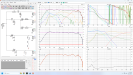
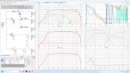
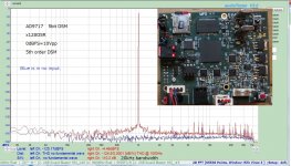
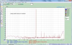
Two major strategies are mandatory to achieve the goal. FPGA and transistors with them can already outperform my DIYed 5bit DSM DAC, though the 1st pic is still an experimental result. THD+N is around 113dB, which is an almost impossible number for my 5bit DSM because it has a DAC chip(AD9717). The most challenging or impossible thing for a DAC chip is to have no noise floor fluctuation. I'm sure as long as a DAC chip has a resolution, even if it's 2bit, noise floor fluctuates as the amplitude becomes large. The 2nd pic is DIYed 5bitDSM(my 3bitDSM version also has the same plot). THD+N of 5bitDSM is around 110dB. If it wouldn't have a noise floor increase, you could have the same value as pic 1. THD is excellent because this is just after calibration. It matters little, and two or three days later you can't have the same number.

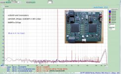
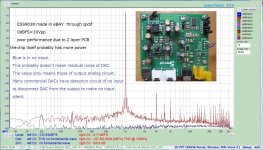
The 3rd pic is ES9038 made in eBay. This isn't a real performance of the chip since PCB is poor. If you use the chip at -0.1dBFS, the performance becomes far worse(the plot is at -2dBFS). Recent commercial chips usually don't have the best performance at fullscale. PCB construction is inevitably essential. I'm sure even carefully designed PCB can't remove noise floor fluctuation. So is AK4499. AK's homepage has two plots.
TECHNOLOGY | VELVET SOUND | AKM - Asahi Kasei Microdevices
One(the former) is at -155dBFS,the other(the latter) is at 0dBFS. You can see a moderate(6 to 8dB) noise floor increase. I would say low noise floor fluctuation doesn't exist in their to-do list.

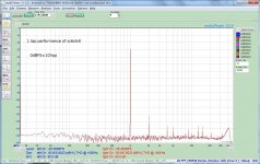
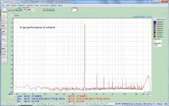
1bitDSM itself has an ordinary performance like the 4th pic, though noise floor level and absolute THD are excellent. Small signal level(-28.35dB) prevents you from high performance. One of the two necessary strategies is analog FIR, which is used by pcm1792 in DSD mode. I haven't yet fully understood why it can increase signal amplitude without degradation of THD+N. It can magically boost the signal. S becomes large by analog FIR while THD+N is intact, where you automatically have a better performance like the pic1. The 5th pic is 6taps analog FIR. Noise floor and absolute THD is almost the same as 1tap. Only the signal does increase. The 6th pic is 12taps. The magic increases only the signal again.

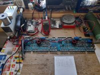
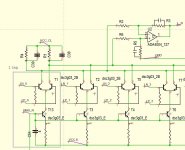
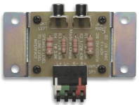
The rest of the two strategies is ECL like the 7th pic. If you replace T13 with a register, it's true ECL. T13 configured to constant current determines signal gain by T1. LN_0 and LP_0 are complementary 1bitDSM signal to switch two transistors of T1. When one is active, the other is inactive. Constant current defined by T13 passes through R4 or R1, where the digital signal(1bitDSM) is converted into an analog voltage. The significant advantage of ECL like conversion is PSRR. LN_0 and LP_0 are a dirty signal from the digital section. But the constant current of T13 is almost irrelevant to base voltage of two transistors of T1, which can result in noise-free transfer to the analog voltage across R4 or R1.

There may be several solutions to have isolation between the digital section and the analog one to have low residual noise. No DAC(1bitDSM) project usually has zero PSRR, where ends up less THD+N and prevents 1bitDSM without a DAC chip from the high-end application. If you have better isolation from the digital side, 1bitDSM can have high SNR. ECL is one of the strategies to make noDAC brilliant. ECL is easy to extend, i.e.,2taps,4taps, and more. The more, the better. The disadvantage is instability. It sometimes ends up an oscillation. I have now 24taps with moderate stability. I haven't yet fixed the oscillation problem. I'm not sure if I can have 32taps for further improvement. I'm still on the way.

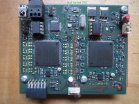
The 8th pic is x128OSR in 8th order DSM. It has almost the same performance as x64. Noise shaping is, of course, better than x64. Xc6slx9 can have up to 5th order. More than 6th is done by external digital PCB(xc6slx25), which is the same one as my 5bitDSM DAC. The pulse train is transferred through an optical cable to keep high isolation. Onboard Xtal based OSC can successfully recover a clean clock(the 9th pic).

Attachments

  • xc6_x64.jpg
    xc6_x64.jpg
    366 KB · Views: 3,574
  • AD9717_1k.jpg
    AD9717_1k.jpg
    381.5 KB · Views: 3,348
  • ESS_1kHz.jpg
    ESS_1kHz.jpg
    411.3 KB · Views: 3,256
  • xc_1tap.jpg
    xc_1tap.jpg
    319.9 KB · Views: 3,181
  • xc_6tap.jpg
    xc_6tap.jpg
    320.7 KB · Views: 3,065
  • xc_12tap.jpg
    xc_12tap.jpg
    321.9 KB · Views: 1,141
  • dsd_42.jpg
    dsd_42.jpg
    150.6 KB · Views: 1,832
  • xc6_x128.jpg
    xc6_x128.jpg
    302.7 KB · Views: 1,849
  • xc6slx_1.jpg
    xc6slx_1.jpg
    437.8 KB · Views: 1,937

Moscode 600 noise every 1.5 to 2 seconds

At turn on, I get a fairly loud noise similar to the noise I get at turn on, but more than twice as loud which will repeat itself every 1.5 to 2 seconds or so.
There are 4 fuses on the board as well as 1 on the power supply on the back of the unit next to the power cord.
It blew one of the fuses on the board. I replaced that fuse as well as the center 6922 and it makes the same noise

Ten yrs ago I replaced all of the caps in the signal path, according to a post somewhere here at diyaudio, with Jentzen caps.
The amp was nodded by George Kaye and had the large Solen caps put in parallel with the filter supply caps.
The filter caps as well as about 6 other electrolytic are original, as well as the black gates
Is this the sound that big cans would make if they are past due? Is this the sound of bad caps somewhere ?
Thanks for your help

For Sale Scan-Speak Revelator drivers

Dear diyAudio readers,

I am selling a bunch of Scan-speak Revelator series drivers. All of them had been used once and only for testing. Overall they are like brand new, minor scratches inside mounting holes because of the screws. PM if pictures are needed.

The drivers on sale:
  • 2x 28W/4878T00 (subwoofer) (700eur retail) 500eur/piece (can be sold separately)
  • 2x 22W/8851T00 (woofer) (350eur retail) 250eur/piece (will be sold olny as a pair)
  • 2x 18M/8631T00 (midrange) (250eur retail) 150eur/piece (will be sold olny as a pair)
  • 2x D2908/714000 (tweeter) (600eur retail) 400eur/piece (will be sold olny as a pair)
All prices are final at the moment and exclude shipping costs. I can ship worldwide, however would prefer Europe.

Help! Yamaha RX-V473 static and distorted audio

Trying to repair Yamaha RX-V473, service manual is at elektrotanya.com/yamaha_rx-v473_htr-4065_sm.pdf/download.html,

On all inputs, all active speaker channels, there is a static-y white noise (a bit like the test tones, but quieter) with distorted audio, except on analogue inputs in Direct mode, when it sounds fine. Digital inputs in Direct mode still have the static noise and distorted audio.

When no input connected, analogue inputs just have the static noise; digital inputs (and tuner, USB etc) are silent. I've done factory reset, firmware update and basic checking of power supplies and regulator voltages, all OK. Also replaced the HDMI board's regulator electrolytic capacitors just in case.

I think that the analog inputs go through DIR/ADC, then to DSP, then to DAC and finally to audio amplifier, except in Direct mode where they presumably bypass ADC, DSP and DAC.
Digital inputs go to through DIR (no ADC needed), then to DSP, then to DAC and finally to audio amplifier. Direct mode presumably just bypasses DSP, as DAC would still be needed.

The DSP functions (sound fields) do appear to work, with correct speaker configuration (and shown on the display), but with the static / distortion on all active speaker channels.

So I'm thinking the problem is likely to be with the DAC or DSP chip, but not sure how to test or check this, or determine which one.

Any help or insights greatly appreciated.

TIA, Jon.

Best Single Rail Amps?

I'd just like to poll your opinions about what might be the better natively capable single rail power amp ICs or module designs?

In terms of 'better' I leave that up to you to explain! 😀

It's far easier to find single rail pre-built SMPS PSUs, which is why I'm asking. I appreciate the lack of 50Hz harmonics from SMPS and the small form factor to power ratio.

Any manufacturers still using LM3886 in their current designs?

Are there any commercial manufacturers still using LM3886 or similar chip amps in their current designs?

If not, why commercial manufacturers shy away from it?

Also the above search lead me to these two patents. I wonder what they are patenting? Their specific modifications to the Typical Application circuit?

Like the Op-Amp buffer?

CN106953607A - A kind of single channel audio power amplifier based on LM3886
- Google Patents


CN105048976A - Power amplifying circuit based on LM3886 chip
- Google Patents

How can I best waterproof speaker fronts for boat use?

I have found four Wharfedale Pro Titan 8 mini PA speakers that I am going to use in my boat for fun. I take heavy metal fishing trips with the boys every now and then, and the 6x9 JBL marine speakers are a bit to weak to really blow the fish out of the water. 🤣 This is how the boat looks with the front 6x9:

1692385106866.png
1692384927438.png


There are a pair of the same type in the rear, barely visible in the back on the closeup. These new speakers are only a little bit bigger than the 6x9 with boxes, but handles much more power. They are meant for outdoors PA use, but not with a direct, heavy water spray like heavy blowing rain or spray from using the boat in 30 knots in waves (they are IP45 rated, but I don't trust that fully).

So my plan is to hang them horisontally under the roof, where the boxes for the 6x9 are now, and build open top 2 mm aluminium sheet boxes around them, bolted to the roof. That will take care of side and rear splash, the problem is front splash for the front speakers, and rain, when the wind comes from the wrong direction and drives it underneath the roof.

I was wondering if it's possible to use alumium sheet as fronts and then have cutouts where the drivers are. But the water resistance is the problem. I would either have to use a kind of a lid and remember to put that in front of the boxes when I dock and remove them again when I'm going out and want some tunes, or find a kind of material that will mostly stop the water from coming in to the speakers. Would for instance a double layer of Gore Tex work for that?

Help: over-sensitive volume pot on Chinese DAC

Hi everyone. I received an inexpensive "Rod Rain" Chinese DAC 2 days ago, and although it sounds nice, normal listening volume is only about 9 o'clock on the volume knob. Is there any chance I can simply replace the pot to give me better control? Having only from 7 o'clock up to the 9 or 10 o'clock knob position means precise adjustment isn't very easy.

I have no idea what the value of the pot is or how it works in the circuit. I asked for a schematic and was denied. A picture of the board is all I have. Note that the op-amps are 4 x OPA1612, not the ones shown in the picture.

I am using the digital coaxial input and the left-right RCA jacks output to my Dynaco ST-70 series ii amplifier.

It works, and I like the way it sounds, but the volume control issue is annoying. I am not an electronics expert or engineer - just a novice with a multimeter and a soldering iron - so I don't know if this is something I might be able to fix or what the fix might be. Suggestions welcome. 🙂

Link the to product: https://www.aliexpress.us/item/3256802716154447.html


DAC.JPG

Replacing 4 ohm drivers with 8 ohm drivers (Wavecor WF182BD03/04)

I have been trying to source the Wavecor WF182BD03 for a project, ufortunately without luck. Instead I have found the Wavecor WF182BD03 which seems to be the "same" model, just 8 ohm instead of 4 ohm.

Is it possible to calculate which modifications would be needed in a filter designed for the 4 ohm version in order to use the 8 ohm version instead?

https://www.wavecor.com/html/wf182bd03_04_07_08.html

About Zobel circuit

I know that the Zobel circuit is to maintain a certain impedance of the load of the speaker at high frequencies. When I test the circuit, the way to measure the impedance is (after measuring the output AC voltage, divide it by the output AC current), but After I came out on the side, whether there is a Zobel circuit or not, the AC current will decrease as the frequency increases. In this way, the impedance will continue to rise, so I don't understand why the Zobel circuit has no function.
Below is my circuit diagram and measure,R9 and L1 are the resistance values of the speakers measured by me.

Attachments

  • 1693020920004.png
    1693020920004.png
    16.4 KB · Views: 218
  • 1693021680768.png
    1693021680768.png
    95.7 KB · Views: 217

Outside The Box

In this vidio of the 2021 BAF Nelson makes a little talk starting at 12:40 called Outside The Box where the main
discusion was about injecting some extra curent into the output stage of an amplifer. But at 20:10 Nelson pipes up and says
" But wait there's more " at this point he describes having some DC bias voltage in the speaker voice coil to lower speaker
distortion. He makes a point that about 1V of DC in the voice coil shouldn't harm most speakers Oh I know this sounds
like herisy but after all the title of the talk was Outside The Box. So this makes me wonder if some of us building a MOFO
using the 193T inductor or an inductor with a lower DCR do we realy need that output cap after all.

Login to view embedded media
  • Like
Reactions: ranshdow

What is the best way to measure transformer output?

Transformers, despite being the heart of every one of these treasured electronic things, are still something of a black art to me. In discussions here about renovating my old components, I've been told to build new power supplies in outboard chassises to reap the benefits of lowered noise, most notably in the Big Sky Adcom thread. I'm ok with the idea, but what if I don't have the value of the original transformer and I decide I want a nice shiny new one without any de-lamination? How do I measure the output of the original transformer to find out the needed value for the new one? Is it just as simple as knowing the output voltage(s) and applying a formula?

FC100 amp looking for a home.

I have an FC 100 (WTB Fc-100 parts). It worked no problems for a few years, but one channel now eating fuses. I have no facilities or the knowledge to track down the issues. I'm offering to any interested parties - FREE. The only catch is you have to arrange to pick it up (it's heavy). I live in the San Diego area.

I built 2 of these - one working, one that went dead after a few years. I'm scaling back and don't have test instruments. The custom transformers alone are valuable (25V@5.2amp/34V@ 0.235).

same deal for the pair

sheldon

Attachments

  • IMG_1607.JPG
    IMG_1607.JPG
    460.7 KB · Views: 309

Confused by tube data (transformer impedance changing with voltage)

Was looking over the N78 tube info http://www.r-type.org/pdfs/n78.pdf and saw something that confused me. Triode AB with 300v needs a 5k output transformer but at 350v it calls for an 8k transformer.

1) Why did the needs of the transformer change so much? Did they just try an 8k transformer and that combo of B+ and current is what was needed to get the distortion that low?
2) Is there a consistent relationship across tubes that you can use to figure out what operating points to use when you have an 8k transformer instead of a 5k one? Or is that always to be found using the tube curves somehow?

3) Aren’t they missing a lot of info to go along with the distortion measurements? Surely different transformers, topologies, etc. will affect the final number right? What did the manufacturers assume when they post distortion figures like that?

Thanks for any help. Still trying to figure out how to read tube data.

DIY phono cartridge

Hello
I am making a phono cartridge as per following specs:
1) micro ridge stylus with sapphire cantilever
2) rubber dampers
3) Mild steel gold plated poles/ yokes
4) 0.027mm pure coper enamelled wire
5) samarium cobalt magnets
6) cartridge body/base made of titanium.

i have finished making MC cart but it is sounding very harsh.
Does anybody have suggestions.

Attachments

  • BDD3B20E-BE11-4B98-A931-7794E47393A2.jpeg
    BDD3B20E-BE11-4B98-A931-7794E47393A2.jpeg
    449 KB · Views: 1,139

Should I replace unknown-hour tubes from 2001 that came with an amp I bought?

The amp is an Audio Research D70 MkII. The tubes are Svetlana branded with "01" date codes. Beyond that, I have no idea how many hours are on them. Everything seems to work properly, no arcing or sonic issues.

Should I have them tested? Should I replace them with new? Should I run them until they start causing problems?

Voice coil inductance calculation with Kr, Ki, Xr and Xi

Do someone have tried to calculate voice coil inductance with the Kr, Ki, Xr and Xi parameters published in ZMA files, as those published by Parts Express for Dayton Audio woofers?
I tried with bad results.
You may like to see my calculations in attached Excel spread sheets. I do hope you don't mind that are in spanish.
I tried both models: one from J. R, Wright (An Empirical Model for Loudspeaker Model Impedance) and other from Marshall Leach (Loudspeaker Voice-Coil Inductance Losses: Circuit Models, Parameter Estimation, and Effect on Frequency Response).
In the file named "Leach-Wright_3a" I've tested Kr, Ki, Xr, Xi Wright's parameters of the DSA175-8 woofer to calculate real and imaginary values of Zem of the motor impedance model, but when I add them (as complex numbers they are) to Re (the DC coil resistance), and Zms (the electric equivalents of mechanical mass, spring and damping of moving parts), the values obtained for Zvc of the voice coil, they disagree with those published in the ZMA file. This is evident in the plot of the calculated values over the impedance graph published with the specs.
In the same file, I calculate the n and K parameters of the Leach's "lossy inductor" model. With them, I get good agreement with the ZMA file values for the cited woofer.
In the file named "Leach-Wright_3b" I get my own values for Kr, Ki, Xr, Xi Wright's parameters, in accordance with his paper. The situation changes to "good agreement" with published data.
I did a second test with published and calculated values for the RS150P-8A woofer, also from Dayton Audio. Again, I got good agreement with values of Wright's parameters calculated by me and not with those published.
What could be happen?
I would like to read your comments.
Kind regards.

Attachments

Chinese ES9018K2M I2S DAC

Hi all.

I bought this DAC from aliexpress.

I connected a 12V DC power source and also connected the I2S lines and GND to a Raspberry Pi 3 with Volumio. In playback options I selected Generic I2S DAC as the DAC model. After this, I get sound in my speakers, however it comes with a lot of noise, that makes it impossible to actually hear the music.

Does any one else also has this DAC? What can be done to remove the noise?

Thanks.

P.S: I'm using a breadboard to connect the I2S cable through jumper cables to the Pi. I do realize that this is not the best option, but I do doubt that this is what's making the noise.

Altec 290E - modify?

Greetings all,

I have acquired several ALTEC 290E drivers, without the matching 15045A transformer and the rear cover. From research, the driver has the same motor assembly including the AlNiCo V magnet as the 288, but is fitted with a phenolic diaphragm, which is allegedly more weather resistant and can handle higher power, since the driver was intended for public access and outdoor usage. There downside is limited frequency range of operation. https://greatplainsaudio.com/wp-content/uploads/2016/06/290-Series_hfdriver_spec_sheet.pdf

I confirmed that the motor assembly, i.e., the phase plug and the gap, is the same as the 288 by trying an Al diaphragm from the 288, which fits - in a third world wort of way. The problem is that the metal and plastic rim of the phenolic diaphragm has larger outside diameter and the holes for bolting the diaphragm to the top plate are on a larger diameter, so that the Al diaphragm cannot be bolted.

I do not think that there will be much interest in it, since the matching 15045A transformer and the rear cover are missing. Consequently, I was thinking about modifying it to accept the Al diaphragm. There appear to be the following options:

(i) re-drill the top plate, which de-valuates the drivers even more;
(ii) machine a ring that will bolt into the original holes in the top plate and secure the Al diaphragm; and
(iii) machine a new top plate.

(ii) and (iii) are attractive in that the modification is reversible.

Any comments?

Kindest regards,

M

QUAD 405 (original version) with no treble on one channel

Hi all !
I need your help/advice, I have the following problem with my Quad 405 (original one) since yesterday evening: the sound is messy, treble are not soft, they are "brittle".
The amplifier have been "refreshed" using Dada Electronics kit (many) years ago, the power supply is a dual power one from Net-Audio (UK). I use the amplifier daily (used for the TV). Preamp (44) is not the issue as when connected a 405 clone I had built years ago (Hungarian kit) I do not have this sound issue (despite this clone doesn't sound as as the original one), so I use the "clone" as long the other one is not repaired.
As I do not have a scope beinglimited to voltmeter/ohmmeter, I did check if there were any offset voltage on the outputs: nothing wrong (both <0.01 V)
Anyone having an idea where it can come from ?
Thanks in advance,
Michel.

Manual combination for drivers and crossovers

Hi, I am new to DIY, i know how to soldering, caps, resistors and inductors together, but I dont know how to combine them to match different drivers to get the best crossover point.

Wondering any website they have huge archive of crossover diagrams to match different driver? Such as Seas, Morel, scanspeak, hivi, etc or even those branded speakers.

If have, could you share with me?

Much appreciated, thanks.

Need help identifying driver

Recently picked up a pair of Audiovector/F3 bookshelves that I am unable to identify, from an estate sale.

One is in perfect condition, but the other one has a voice coil rubbing in the woofer. As i'm unable to find any info about what model speakers these are, I'm also unable to find out what driver is being used.

(SR142/12 in the first pic i believe just references the rubber surround part#)

Can anyone help identify? There's also a chance the driver isn't being produced anymore, so i'd probably have to find something that will perform similarly. Driver is ~6"

IMG_0156.jpg
IMG_0159.jpg
IMG_0162.jpg
IMG_0164.jpg

For Sale 2 x TAD TD-4001 + 2 x B&C DCM50

Hi,
I have to much stuff not being used so if someone is interested here it goes.

TAD TD-4001 SOLD!
Both motor units are in very good condition and was re-charged in 2016. Unfortunately there is only one good original Be diaphragm, the other one has a cracked suspension after a drop in the floor by me........ There are also two Radian 1292-16 diaphragms and they are the ones mounted now. They are also very good and if the drivers are going to be used for only midrange duty I actually prefer them over the original.
I'm asking for 1500 EUR the lot.

B&C DCM50 16 Ohm
SOLD!
This pair have seen maybe 50h of lite use in a hi-fi set up so they are practically new.
Asking 500 EUR for the pair (new ~800 EUR)


BR,
Anders

Bridge (BTL) mode in ICEpower 700AS2

Can I run the ICEpower 700AS2 in bridge mode?
I need to connect ONE 8ohm speaker and want to deliver no less than 800watt.
According to the documentation for driven two channels, this module achieves a power of 550watt @4ohm per channel (1Khz 1%THD).
I assume in bridge mode it should be ~1100 watt @ 8ohm.

Unfortunately, the documentation does not contain any information about this mode.

For other modules, such as ICEpower 300A2, there is a description in the documentation on how to run the BTL mode.

Thank you very much for your help.

For Sale SunValley SV-S1616D SET Class-A KT170 Tube Amplifier

FS is a SunValley SV-S1616D SET Class-A KT170 tube amplifier, which I built last summer. The original kit costs a little above $2000 (not including tubes). It has broken in now, but with low usage.


KT170 starts getting popular recently. It sounds very nice (In my opinion, it probably sounds even slightly better than 300B).

More info can be found from: https://www.diyaudio.com/community/threads/sunvalley-sv-s1616d-300b.371736/

It is configured at 120V.

I've also made following upgrades.

--Hashimoto H-20-3.5U OPT
--VCAP ODAM 0.1 X 2 , 0.22 X 2
--Belton sockets
--Takman resistors
--Mogami microphone shielded cable which has very low microphonics


The sale package will include
--SV-S1616D SET class A tube amplifier
--12AU7 X2
--12AT7 X1
--Tung-sol KT170 X2
--Tung-sol 5AR4 rectifier tube

$1700 and free shipping CONUS.

Sorry no international shipping.
20230824_075309.jpg

Millett Mighty Midget - blowing fuses

I've just finished assembling the PCB and chassis for a 6T10 Pete Millett Might Midget build and the fuse keeps blowing when powering on.

It's a decent pop as well (you can see the damage to the fuses in the attached pictures).

I tried a few sets of tubes but the problem remains, so I assume there is an error in my circuitry.

The circuit and more info is here on the brilliant @pmillett site:

http://www.pmillett.com/midget.htm

What would be the best testing points to determine the error when the circuit can't even power on?

Attachments

  • IMG20230827112244.jpg
    IMG20230827112244.jpg
    357.6 KB · Views: 94
  • IMG20230827112246.jpg
    IMG20230827112246.jpg
    307.3 KB · Views: 93
  • IMG20230827112251.jpg
    IMG20230827112251.jpg
    561.6 KB · Views: 96
  • IMG20230827142404.jpg
    IMG20230827142404.jpg
    768.8 KB · Views: 88
  • IMG20230827142418.jpg
    IMG20230827142418.jpg
    757.4 KB · Views: 104

2021-2023 Ford F150 and Expeditions -- Class D gone wrong

From this morning's Wall St. Journal (8/23/23). I have a 2023 Expedition and have only once experienced the squeal:

Phil Floraday was driving his F-150 pickup last fall when his truck’s audio system suddenly emitted a loud, crashing sound that, to him, resembled glass shattering, and then blaring static.

His ears rang for days after the event, he said.
“My first thought was one of the neighbors must’ve hit a golf ball that went through a window because that’s what it sounded like,” said Floraday, who took delivery of the 2022-model-year truck last summer.
Ford Motor F 0.15%increase; green up pointing triangle is confronting a problem with some newer pickup trucks and large SUVs: drivers reporting cases in which the speakers in their vehicles sound a loud and abnormal noise—often frightening the occupants.
On online forums, F-150 owners have been airing similar accounts of an odd sound, which some describe as a “sonic boom” or “ear-piercing static.” Drivers, in some cases, were able to turn it off right away. Others say it lasted for 15 minutes or more, persisting even after the car was shut off.

Several dozen Ford customers have filed complaints with federal regulators, saying the noise was so distracting they either had to pull over and stop driving, or if parked, didn’t feel it was safe to get on the road.
The automaker issued a technical service bulletin to dealers this summer to try to address the audio issue, which it said is related to the amplifier in the vehicle’s sound system.
A Ford spokeswoman declined to disclose the number of vehicles affected. The service bulletin covers the Expedition SUVs and the F-150 pickups from the 2021-23 model years and the 2022 F-150 Lightning electric trucks.
Ford’s F-Series pickup truck has been America’s bestselling vehicle for decades.
The car company has received about 100 complaints related to the problem, primarily involving the 2022 F-150 truck, the spokeswoman said.
“We are working swiftly to make sure this is resolved for our customers,” she said.

DSR112s crumbling apart

Guys,
i scored a pair of second hand yammies DSR112's
those things are LOUD and clear (well , coming from sub 600 bucks a piece tops i am amazed)
my 1st experience with a FIR DSP plate amp is great!

some comers are damaged and looks like is not plywood but MDF(yuckk)
some questions

is it feasible to transplant the LF driver and the HF/lens drivers and plate amp
to a 15mm plywood enclosure ? (do i need to use 18mm ? hope not )

of course i will keep the same area for the 12" LF driver and the 2 relfex ports size dimensions on it
the best i can to maintain the match of the FIR factory calibration
also
do i need to brace it like a subwoofer ?
also what inner damping material i can use
i found this plan on youtube

Login to view embedded media

Four O-Netics 6BQ5 8K PP OPTs

I have four O-Netics standard grade 8K 15W push-pull transformers. I measured the primary windings of each with a meter (brown, white, and light blue wires) and verified that each half of the primary is a consistent 45 ohms or so. All the secondary wires on each transformer show the appropriate continuity, and I don't see any primary to secondary shorts on any of these. Three of these look like they have been used for some purpose and one looks to be new and unused. Due to the age of these transformers, there is a bit of surface corrosion on the covers and a bit on the stack, but nothing that couldn't be cleaned off prior to a fresh coat of paint.

Asking $500 shipped CONUS.
IMG_20230706_144957.jpg

IMG_20230706_144938.jpg

ALPS RK 27 motorized reinforcement volume Lite

Dear Friends,
I kindly need a little help: I have Lite G-05 similar to MV02-04-06, and I have to pilot 3 ALPS RK 27 in parallel. I've tried many ways but the circuit board is able to pilot perfectly well only two potmeters at the same time, outputting 4,5 volt approximately as foreseen. If I put a third motor in parallel to the other two, the voltage fall to 800mv approximately. I have tried to wire them in series or putting limiting resistors (10ohm) on each one, but it doesn't help.

The circuit seems simple but it works with two polarities, and also I have no experience with the outputs of a microprocessor... what will you reccomend to modify to increase the piloting strenght?
Thanks a lot! Gianmaria.

1693063221389.png

Hafler DH 110 grounding inputs and signals

DIY, Need some help. I have a Hafler DH 110. Here is the problem. The selector switch grounds all inputs not selected. So, when I select tuner the CD/AUX is grounded and vice versa. Here is the problem. When I have a signal going into the tuner and then select the CD/AUX, Tape 1 or Tape , there is a faint signal that can be heard. I was under the impression that grouneded inputs meant dead silence. I checked he manual and it tells me how to make sure the outputs are functioning. I also checked each output as I turned the selector switch and sure enough they are grounded. I cannot figure out where the extraneous signal is coming from. I have attached the schematic for reference. Any ideas or troubleshooting help would be appreciated. And if this is normal behavior for this preamp that's okay too. My APT Holman does not do this. Thanks again. Mark

Attachments

CD player hard shuts off above certain line voltage

Hi all,
I have a Denon 1290 CD player that abruptly shuts off when the AC voltage approaches ~215V, the CD stops spinning and the display shuts off. I've tested the player on a variac and it works fine up to 215-217VAC while it's a normal 220-230V EU model and also has no voltage selector.
The main voltage regulators do keep producing normal voltage, the usual transistors also stay warm even if the player seems 'dead' at normal line voltage.

Any ideas? I've tried unplugging what can be unplugged and trying again at ~225-230VAC but that doesn't change anything - dead, if I lower the AC, the player wakes up again.

ICEpower amp vs Purifi

Hello everyone! I had purchased an IcePower 1200AS module a few years back and was wondering about the Purifi component/s compared to the Icepower modules? I'm not fully sure what all is involved for a DIY assembly of the Purifi, as the Icepower came with everything on the PCB minus the enclosure, connections and such. I do think that the Icepower 1200as sounds good, but I have heard that this Purifi set up is much better? I'd appreciate any feedback, Thanks!

Russound ADP-1.2 modification advice Speaker to Line Level

I have a Russound ADP-1.2 that I am using to take my speaker-level output, down to a line-level output. It works fine, but there's not enough power going to the amp which is driving my woofers for bass.(Crown XLS 1002).

The specs on the Russound says it decreases the level by 30db. In order to get the bass to the level I want it, I have to max out the dials on the Crown amp. I'd much rather have some headroom to play with, and minimize any hum I'm getting from the amp since the levels are maxed out

I would like to replace the resistors with something less aggressive in order to get a -15db or a -20db, instead of the current -30db.

Anyone who really knows about resistors that can help?

Attachments

  • Screen Shot 2023-08-26 at 7.53.27 PM.png
    Screen Shot 2023-08-26 at 7.53.27 PM.png
    515.6 KB · Views: 161

Cyrus III power amp schematic here, but schematics of the later models wanted

From the integrated amplifiers Mission Cyrus ONE and Cyrus TWO there are PDF schematics here:
https://www.hifiengine.com/manual_library/cyrus/1.shtml
https://www.hifiengine.com/manual_library/cyrus/2.shtml
https://www.hifiengine.com/manual_library/cyrus/3.shtml (incl. "i")
check out the overview for service manuals of the later models from Cyrus
https://www.hifiengine.com/manual_library/cyrus.shtml
and for Cyrus IIIi I did create a schematic diagram some years ago (see PDF upload) and compare to the genuine schematic published later - not too many errors in my own schematic
But where are schematics of the later models Cyrus 8, Cyrus 8vs, Cyrus 8vs2 and Cyrus 6 (not included in the associated service manuals) so as from the currently version of Cyrus ONE ?
By study the schematic diagrams of power amp sections of the various models I note, that only the Cyrus IIIi looks the most interesting of all (due current control global NFB mostly called "CFA").
It is similar to OMTEC's topology - go to post #12 under
https://www.diyaudio.com/community/...amplifier-ca-25-ca25-schematic-wanted.160949/
last image and this kind of NFB is discuss here:
https://www.diyaudio.com/community/threads/cfa-topology-audio-amplifiers.240712/
All the other models are designed as "VFA" as kind of NFB (maybe except the models Cyrus 8, Cyrus 8vs, Cyrus 8vs2 and Cyrus 6 from that no schematics to find - but is rather unlikely, since the XP versions of Cyrus 6 + 8 according the simplified schematics are also designed as VFA).

Is this anywhere described this fact on the Cyrus-website and justify why one did it that way ?
Or only those who know the circuit topology from power amp sections of all Cyrus integrated amplifier models know that ?
Under
https://www.cyrusaudio.com/products/cyrus-3i/
is mentioned only this:
The Cyrus IIIi is a conservatively rated 50W per channel integrated amplifier designed to become the core of a quality audio system. Following in footsteps of the well respected Cyrus I & II, the Cyrus IIIi is an ‘improved’ Cyrus III which has moved on to address the life style requirements of the 90s as well as having the ability for expansion into a fully integrated audio-visual system


Here some other threads without help:
http://www.diyaudio.com/forums/solid-state/153794-mission-cyrus-iii.html
http://www.diyaudio.com/forums/solid-state/153502-cyrus-3-a.html
http://www.diyaudio.com/forums/solid-state/146116-cyrus-3-cyrus-iii-amp-help.html
http://www.diyaudio.com/forums/solid-state/21901-cyrus-3-reconfigure-use-without-psxr.html
http://www.diyaudio.com/forums/solid-state/86367-cyrus-3-amplifier-component-mistakes.html
http://www.diyaudio.com/forums/solid-state/86122-cyrus-3-rescue.html
http://www.diyaudio.com/forums/solid-state/50824-cyrus-3-amp-problem.html
http://www.diyaudio.com/forums/solid-state/22595-cyrus-3-service-manual-anyone.html
http://www.diyaudio.com/forums/chip-amps/141464-cyrus-3-gainclone-project.html
http://www.diyaudio.com/forums/solid-state/120210-cyrus-iii-intergrated-amplifier.html

Thank you for your advice for finding schematic for power amp section of Cyrus 6+8

Attachments

semiconductors

HI.
currently what is the state of the art for semiconductors?.
is silicon still dominant?.
for example gallium nitride was discovered in 1990 , I do not know if there are commercially available transistors , mosfets or fets made with this material .
https://epc-co.com/epc/gallium-nitride/what-is-gan
https://audioxpress.com/article/gan-technology-in-audio-power-amplification
is there anything else?

Series 500 Hairball Audio Lola preamp for sale

500 System Hairball Audio Lola preamp with a little DIY for sale.

It was bought as a kit sometimes ago, and has been nicely assembled by an experienced guy.

All the controls and the VU meter seems to work, but there are some problems with the volume control,
less on one channel and more on the other. I can send a test report of what I did to test it, and the results.

Hairball have accepted a repair and sent me a repair return number. They charge around $75 for a test plus
time and parts for the repair. I just haven´t pulled myself together and sent it in for repair.

It can be sold without op-amps, but I have 2 Sonic Labs 990 Pro op-amps that are brand new and tested to work,
and a single Sound Sculpture lunch box that are tested to work, that can be bought also. (I will not sell the op-amps
without the preamp).

Pricing
Lola preamp, Euro 135
2 Sonic Labs 990 Enh Op-amps, Euro 135
Sound Sculpture Single lunch box, Euro 135
Transport in EU, Euro 30

Sound-sculptor1.jpg
Sound-sculptor3.jpg

The parts are located in Denmark, and can be sent with for instance GLS.
Lola3.jpg
Lola0.jpg
Lola1.jpg
Lola2.jpg
Lola4.jpg

Professional 500 Series Host / Mini Lunchbox / S500 Docking Station from Sound Skulptor in France

Professional 500 Series Host / Mini Lunchbox / S500 Docking Station from Sound Skulptor in France, a known vendor of S500 devices.

It can be used if you want to make a S500 device a stand-alone device, or just want to test it in different circumstances.

It contains low noise power supplies for +/- 16v and 48v phantom power and possibilities via a screw terminal to patch the module as wanted. It comes incl. documentation, which though not contains information how to patch the screw terminal.

The screw terminal is labeled, but seems to prerequsite that you know the S500 system well. The list price of the product is Euro 380. My price is Euro 160 plus transportation Euro 15 inside the EU. It is like new.

Help with modifications to speaker plans - Sub design

Hi all,

First time posting so just want to say a big thankyou to everyone on here - it's an absolute wealth of knowledge that's been super useful in helping me get to grips with some of the basic concepts of speaker design.

I'm trying to design a sub to support an altec 816 cab, I've been thinking about trying to build the C-Sub from speaker plans, link below, but make some modifications to the width and depth of the box such that the altec will sit nicely on top - in its current state the altec would overhang on all sides.
https://www.speakerplans.com/index.php?id=csub

I'm quite happy with modelling how the volume changes affect the tuning of the rear chamber of the box using Win ISD, that's fine. What I'm unsure about is how these same changes will affect the top chamber?
Could anyone please explain how I'd go about this - would it be a valid option to just keep the volumes of each of the chambers the same whilst messing with the width/depth or will I need to also think about changing the top vent size.

Also open to any suggestions of sub designs which would better suit this altec cab (slightly modified, and to be fitted with faital pro 15PR400).

Many thanks!

My FR10HM corner-ceiling-floor-array

Intrigued by some corner array projects here, I decided to build myself a pair for the summer house. After some investment analysis I went for the cheap path and got 50 pcs of:

FR 10 HM - 8 Ohm | Visaton

Cost was 310€ taxed and shipped via Mouser.

Corners are 190+ cm high so 18 drivers in per array.

6x3 => 3,75 ohm.... any other way to do it?

I hope for the 20/80 rule to kick in 🙂 and to get some really nice experiences for a less amount of euro. This place is not heated during the cold and damp winter so better not go full in this time. Next version will have to be with 10f/ if this seem to turn out well 🙂

Pictures and impression as things unfolds...

//

Attachments

  • gtha4.png
    gtha4.png
    103.2 KB · Views: 1,214

TA-F444ESII

TA-F444ESII Hi I'm after any info regarding this model as I have recently purchased this amp not working. The problem is it is going into protection after around a minute 30 seconds. It does have an LED lit on the right channel but not lit on the left. Now should both LEDS be lit up or should they both be out? I am aware of resistors going out of spec and have ordered them. Any pointers would be greatly appreciated THANKS IN ADVANCE!

ML-335 or 336 Service Manual

Greetings Folks,

Am working with a family member to diagnose and repair their treasured ML-335 which an uncooperative authorized ML repair center performed repair work on and sadly still has issue which the dealer is unwilling to diagnose and repair without an additional fee. He can’t afford another multi thousand dollar fee , so I’d like to, help, but before I get in too deep into D&R I’d like to ask if anyone in the community would be able to please share the service manual or any circuit diagrams?

Thank You in advance. Phil

RF BD1000.1 repair

I have a bd1000.1 that I'm finally getting around to repairing. I was the original owner, bought new from the dealer. Years back I remember there was no drama with it... worked well,. Just suddenly went into protect the moment you turned it on and that was it.

Opened it up... saw c59 and c60 caps have vented out the top - removed them. Also found J105 (one of the two 16-18awg solid U shaped bars) was loose. Looks like one end wasn't soldered at all and the other end burned. Cleaned it all up and soldered both sides well. I couldn't spot them on the schematic but they appear to bring input power to the opposite side of the board.

Amp turns on now. Protect light comes on for a few seconds and then goes out as voltage builds. Is that normal? It reaches 86v.

I don't have suitable replacements for c59/60 yet. Can I put a light load on it to test it without them, or should I wait?

Cabinet refinishing

Hi, firstly I'd like to introduce myself (couldn't find an introduction forum), so "hello" to everyone!
I have a pair of JBL L110s, the cabinet is in quite good condition but the veneer isn't great anymore, bits are missing etc. I'm no good at woodwork so new veneer is out of the question. So, if I patched up the missing bits of veneer so the surface was nice and even, what sort of finishes would look good on them? I'm thinking of something that I can spray on but I'm open to other suggestions 🙂
Thanks in advance.
Projects by fanatics, for fanatics
Get answers and advice for everyone wanting to learn the art of audio.
Join the Community
507,650
Members
7,882,730
Messages

Filter

Forum Statistics

Threads
405,964
Messages
7,882,730
Members
507,650
Latest member
Sanjiev