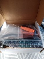
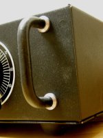
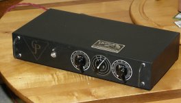
James Loudspeaker A2.1 amp trouble
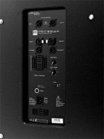
I have a James loudspeaker a2.1 amp with a humming noice on the .1 (Subwoofer) output, sounds very much like wind blowing and it comes and goes but never disapear complitly.
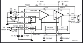
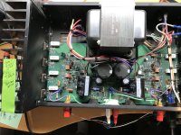
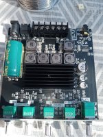
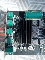
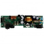
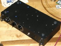
I have no idea what kind of amp it is but my gues is chip class ab or class d amp, it has a Switch mode power supply if it makes any differens.
Any suggestion where to start the localisation of the problem.
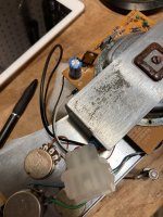
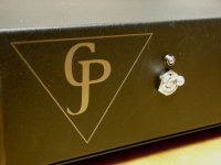
The sub channel has a phase 0/180 degree button on the front. When I press that button it gives som scratching noice.
My hope was a cold soldering but after trying to resolder the legs to that bitton it stays the same as before.
James loudspeaker does not answere my e-mail or messenger messages. I have no schematics for the amp.
Where to start?
I have no idea what kind of amp it is but my gues is chip class ab or class d amp, it has a Switch mode power supply if it makes any differens.
Any suggestion where to start the localisation of the problem.
The sub channel has a phase 0/180 degree button on the front. When I press that button it gives som scratching noice.
My hope was a cold soldering but after trying to resolder the legs to that bitton it stays the same as before.
James loudspeaker does not answere my e-mail or messenger messages. I have no schematics for the amp.
Where to start?


 ). So, what are your favorite small form factor audio things?