Methods for assessing vacuum in tubes

I was intrigued by the sound differences between ECC83 tubes of different manufactures, even though on the cathometer they looked about the same, that is why I propose an indirect determination of the vacuum quality in the tubes by measuring anode current at a very low voltage. Worn tubes or with air in them give current values a hundred times higher than normal and smaller differences occur in tubes with different manufacturers, what do you think?

Attachments

  • 20240324_110322.jpg
    20240324_110322.jpg
    321 KB · Views: 68
  • Like
Reactions: tubelectron

Focal 7C03 info

I have a pair of these (along with 2 other driver pairs that I think were intended for a 3-way speaker) and am trying to find info about them. T/S or other specs would help. They are 6.5 or 7" drivers but other than that I've got nothing. There is little on-line. I've contacted Focal directly but don't expect to get much from them. They have 2 sets of wiring posts almost as if they have dual voice coils - I'll figure that out soon. I'm re-doing the surrounds (foam was shot) and would like to experiment with them in some kind of multi-way box. Thanks a ton for any info you all can provide!

Oddball subs - SRT IBS

I picked these up for the price of the drive. I've never seen anything like these and they peaked my interest, I was told they were removed from a theatre. The previous owner said they have some weird water bladders inside that are supposed to do some funky science stuff, basically more felt bass. It is a dual opposing bandpass setup, with the water bladders in the sealed chamber. the bladders are supposed to be made of some special vinyl, I can hear water sloshing around when I moved them. We will see how they perform.

There are 5 total units; 4 of the smaller dual 10" models, and 1 larger dual 15" model. 3 of the smaller units are missing the woofers, so just the cabinets. I was immediately drawn to the dual 15" model, the woofers looked stout. A quick test with a voltmeter showed both subs as open. I pulled them out and then noticed they were dvc. They were only wired to one coil, and those were blown, the coils not being used seem to test fine. I'm not sure if they were designed to only use one of the voice coils but I am thinking about just trying it on the 2 good ones. I know they can only be used with half their rated power, whatever that is.

There is virtually nothing out there on these things, but I did find some old thread about an advertisement. It said the 10" model went for around $800, and the 15" model around $1400 (circa 2003-ish). No power handling specs, nothing. The fact that there is nothing out there on them and they went out of biz long ago, makes me question the water bladder tech. Non the less, they should be fun to mess around with. The box is made with 1" birch plywood. I haven't torn into the 10" model yet, but I did ohm them out and they tested ok.

Anyone heard of these?

Attachments

  • 20240318_163503.jpg
    20240318_163503.jpg
    629.2 KB · Views: 116
  • 20240318_163617.jpg
    20240318_163617.jpg
    412.1 KB · Views: 102
  • 20240318_163513.jpg
    20240318_163513.jpg
    626 KB · Views: 103
  • 20240318_163528.jpg
    20240318_163528.jpg
    491.4 KB · Views: 100
  • 20240318_163521.jpg
    20240318_163521.jpg
    485.2 KB · Views: 105
  • 20240318_163538.jpg
    20240318_163538.jpg
    475.1 KB · Views: 100
  • 20240318_163547.jpg
    20240318_163547.jpg
    171.6 KB · Views: 95
  • 20240318_163623.jpg
    20240318_163623.jpg
    318.2 KB · Views: 102
  • 20240318_163629.jpg
    20240318_163629.jpg
    257.9 KB · Views: 97
  • 20240318_164122.jpg
    20240318_164122.jpg
    263 KB · Views: 102

Best SMD resistors for AUDIO

A quick search here on the site doesn't come up with much .

SMD resistors for audio
from 2007.
Vishay Audio Resistors
from 2008.

So anything new about SMD R's for AUDIO ?

Looking on the Mouser site , two affordable types : Thick and thin film resitors
with prices overlapping each other. So what to choose ?
Seems thin film is the best for audio :
Thin and thick film >> Resistor Guide

But are the fair priced like this one , much different to the more expensive ones ?
RP73PF1E1K0BTDF TE Connectivity / Holsworthy | Mouser
Some datasheets I looked at , don't even give information about what metal they use. The TE says NiCr.

Decades ago at the electronics store there where the green ones , said to be carbon, and the black ones , said to be metal film. Now if you look on Mouser , most look the same and black. Even now at the retail shop , they can sell a cheaper thick film as a thin film because they look the same with minor differences between
manufactors. How can you tell .

Ordering from Mouser seems less risky although you never can be sure whether you received the what you ordered.
Oh and then there are the SMD milf , oops , MELF resistors :
MELF Resistors | Mouser

So what is the best affordable thin film for audio in 2019 ?

  • Locked
For Sale Ryan D3 TDA1541 DAC build kit

For sale Ryan's D3 dac along with all the transformers, low noise power supplies. The D3 and I2S simultaneous boards are tested with the same supplies as listed below. The PCB boards are built using very high quality caps, transistors and other components. The chip is original NOS TDA1541 unused (not a de-soldered one). This is a complete kit all soldered using WBT and ready to be mounted/tested in your own chassis. I will not split this and would like to sell as a kit as whoever buys it will get a highend TDA dac kit. Rcore transformer have been purchased keeping in view the dac build with the right secondary voltage and current consumption.

Expecting $900 including shipping within CONUS. I think the D3 dac board soldered usually is being sold for $699 - https://docs.google.com/forms/d/1ZM...dI3CQEFt1b1iGvBE/viewform?edit_requested=true, and mine is including all the rest of the stuff to make a complete TDA DAC so at my asking price its a steal.

What is included:

Package sale for $749 including shipping within CONUS.
1. Ryan's D3 TDA1541 DAC board + NOS TDA1541A chip
2. Ryan's I2S to Simultaneous
3. PEDJA IV output stage (Someone not interested in this but D3+I2S board PM me and we can work out a deal)

Ping me if someone is interested for the rest of the components as a package or individual.

4. Diyinhk XMOS DSD I2S Dac
5. Salas Clone Ultra BiB positive supply for +26vdc for D3
6. DIY Ultra Low Noise DIY LT3042 for +/-15vdc for PEDJA IV
7. DIY LM317 low noise DIY +5vdc and +3.3vdc for D3/Simultaneous/XMOS
8. Diyinhk LT3042 low noise PSU for +5vdc and +3.3vdc for D3/Simultaneous/XMOS
9. RCORE Transformer rated - 30VA @ 12vac*2 + 9vac*2
10.RCORE Transformer rated - 20VA @ 24vac*1

Attachments

  • IMG_0506.jpg
    IMG_0506.jpg
    784.4 KB · Views: 348
  • IMG_0507.jpg
    IMG_0507.jpg
    765.3 KB · Views: 331
  • IMG_0508.jpg
    IMG_0508.jpg
    534.3 KB · Views: 294
  • IMG_0509.jpg
    IMG_0509.jpg
    511 KB · Views: 345
  • Like
Reactions: Prodigy85

Toroidal & DC motor

while I was doing research, I met this website with the toroidal question asked on the forum. I realized later that there was a site related to sound systems. I would like to ask a question about toroidal transformers. i want to use the toroidal transformer with a dc motor. but I don't know how many amps this transformer has. there are only volt values on the label on the transformer. how can I find the ampere value of the toroidal transformer? i want to connect a 24v 5a dc motor to a transformer, does this cause problems?
20240302_161430.jpg

20240302_201625.jpg

For Sale Single PSVANE 300B tube

SOLD!

While I was building my 300B amps a few years ago, someone suggested to me that I pick up a PSVANE 300B tube to use for testing purposes as I built my amps and was tweaking the power supply so I wouldn't inadvertently damage the more expensive EML meshplates that I picked up from Jac. This turned out to be a useful suggestion, but now that my amps have been completed, I have a single tube laying around that probably has no more than five total hours on it. It ran with a B+ voltage of no more than 400v and its heater never saw voltage above 5.15v DC. It's virtually brand new and works/sounds great. I just don't have a use for it anymore.

Perhaps someone else might find a use for it rather than having it collect dust in my basement.

Price: $$$ delivered to your door in the continental US.

IMG_09463.JPG


IMG_09464.JPG


This is the circuit that it ran in:

Schematic Joppa Derivative Roberts WE91A 300B - Final Implementation.jpg

Vintage Plush 1060 Bass Amp

I completely restored my Plush 10560 bass amp, replacing all the electrolytic caps and most carbon comp resistors. Also replaced the death cap and installed a properly grounded 3 prong power cord. I'm the original owner. The amp always had excessive gain. Back in the day, they designed them so zero to 4 was the maximum usable gain setting. Made people think their amps were more powerful then they actually were. Anyway, cutting to the chase... Because this gain from the 12ax7 preamp tubes is so high, I get too much microphonics. Anyone see a problem if I replace the (2) 12ax7 preamp tubes with 12at7's to make the volume control more linear and reduce microphonics?

Attachments

  • Like
Reactions: JMFahey

Parametric tone control Question

I've built the DSELF PREAMP v13.01and it works wonderful and now I have a smaller chassis that I'd like to fill. I was looking at this old design, it's actually a 4 band parametric. but I only need 2 bands. I did a bread board test and hooked it up to my Wolverine amp, it actually sounds very good, to my ears.
So before I send the Cad drawing to Fabrication, I was hoping someone here can take a look at the schematic to see if I made any blunders or anything else.
Yes Its old school but I have all the parts.
Thanks all.
Scott

Attachments

  • parametric tone control.jpg
    parametric tone control.jpg
    240.1 KB · Views: 301
  • parametric tone control pcb.jpg
    parametric tone control pcb.jpg
    315.8 KB · Views: 269

how to insert CD tray correctly into Teac VRDS CMK4.0?

Hi all,

This is a bit odd, but some years ago I replaced the tray gear and the sled gear B on my VRDS CMK 4.0 equiped Copland CDA-288 MK. II with no problems.
I had taken the tray off and just inserted it again.

Now, on my other CDA-288, I replaced the sled gear B and reassembled, but now, I seem not to be able to turn the big black plastic gear the sits directly under the tray, to accept the tray correctly. It misalings with gear underneath which lifts the lower puck. And it also seems to be hard to push in the tray the last bit of it's way to fully closed.

Can anyone describe to me how to correctly adjust this and align all parts, so sled sits correctly?

Anything else I should know?

Kind regards,
Jacques

Simplest LDO Soft Start in Thru Hole

These circuits date back to the late ‘90s (below). There are plenty of SMT LDOs with soft start features but I’m not seeing anything in TO-220. I am angling towards using the MIC29152 or MIC2941A for 6V / 750mA, which encompasses two 6922 heaters and some 5V relays running at 4.3V downstream. I’m looking to avoid heavy inrush current. I’m not trying to ramp power over a long interval - even 1 second is more than enough.

In my application power will already be applied, and I am thinking of having a simple SPST “On” switch that toggles the EN pin from ground to open (with the R4/C1 node connected regardless). Is there a snazzier way to accomplish A) the soft start, and B) the turn on, or should I just copy what’s drawn in the ancient Micrel white paper (with R1/R2 corrected of course)? The TI version is almost the same but for an added cap across the upper R in the ADJ network, and the designer assumes an enable voltage separate from the input voltage, which is not the case in my application.

I didn’t bother including the classic LM317 soft start diagram because it has no enable pin.

Go easy on me, I’m not well versed in these circuits.

IMG_7587.jpeg

IMG_7586.png

Rpi 4 + Khadas Tone Board - or not?

Hello,

My original plan was to build a second raspberry pi streamer with the Allo Boss (1.2), which I have done before and am quite happy with.

But that was six years ago... there is a new Allo DAC, and then there seems to be a lot of praise for the Khadas Tone Board.

So I am curious to hear your opinions on this project. I already have the following components:

  • Raspberry Pi 4
  • ESP P05 Linear Power Supply PCB
  • A fun vintage case (broken tape "echo chamber")

What do you think? Stick with the Allo Boss, or give the Khadas Tone Board a shot?
-- oh, and just now I came across another candidate, the Innomaker HiFi Pro DAC (sort of a clone of the Katana they say).

1711056643893.png

MY HI-END audio-pc/streamer

Hello Everyone
This is my last hi-end audio-pc/streamer

It iclude:
  • Ultra linear low noise Power Unit
  • DSD and MQA DAC
  • DVD/CD player/mastering Unit
  • HD touch screen display
  • Integrate temperature control (has one 200mm ultra low noise fan that start only over the set point temp.)
  • Metalized Carbon Fiber Chassis
  • Complete rear pannel connection, also SD card port port for rapid OS change.
  • Windows 11pro/Foobar2000k - monkeymote app remote control (Android/iOS) - wifi USB keypord/pad for playback without internet connection
  • 8Gb Ram, 2-16TB SSD memory library - zero noise CPU/Cipset

Retrofuturistic design (Low level WAF)


I use with esternal good DAC that in the second step will be incuted in a second cabinet/chassis
MPHL_rend2.jpg


backpanel.jpg
mhpl_09.jpg
MPHL_06.jpg

R

Tek 1103 probe power supply + P6245 1.5GHz 1pF probe

This is a Tektronix power supply for two probes with the Tektronix probe interface. One probe is included, the high frequency low capacitance probe P6245, 1.5GHz bandwidth, <1pF tip capacitance. The power supply/amplifier has two independent channels. Each channel has switchable and coarse/fine settable offset. The unit is mains powered and can be set for 110/115V or 220/230V mains. Fully functional. See pics; I have more from sides etc.

Asking € 375. International shipping to most countries is € 33; ask to be sure.

Jan

Attachments

  • 20210808_182541.jpg
    20210808_182541.jpg
    938.9 KB · Views: 134
  • 20210808_182557.jpg
    20210808_182557.jpg
    760.3 KB · Views: 128
  • 20210808_182638.jpg
    20210808_182638.jpg
    677.9 KB · Views: 159
  • 20210808_182655.jpg
    20210808_182655.jpg
    789.2 KB · Views: 119

Assistance sought from a Japanese member.

Hi.
I hope to buy some audio products from Japan, the process seems almost impossible to me. Is there a Japanese member out there who would be willing to lend a hand?
The process would include getting packaging and shipping organised (not doing it yourself as the items could be large). Happy to pay for ones time. Please PM me if interested.
Regards.

For Sale BJT OnSemi (various types)

2SA1943OTU - (5pcs) / 1pcs=4€
2SC5200OTU - (5pcs) / 1pcs=4€
NJW0281G - (5pcs) / SOLD
NJW0302G - (5pcs) / SOLD
NJW3281G - (3pcs) / 1pcs=3€
NJW1302G - (3pcs) / 1pcs=3€
MJL4281AG - (4pcs) / 1pcs=4,5€
MJL4302AG - (4pcs) / 1pcs=4,5€

I'm sending all over the world
Paymet via PayPal
Shipping on request (tracking, no tracking)

Attachments

  • IMG_20240307_093845.jpg
    IMG_20240307_093845.jpg
    340.1 KB · Views: 93

Ticking Noise from ES9038Q2M Raspberry Pi DAC Hat

Hi All,

I can find no information about this here or out there on the Internet, so I'm asking if anyone might have some experience here.

I have an Into-Maker DAC (marked "Skylark" on the board) hat based on an ES9038Q2M chip,on a Pi4 running the newest version of Moode. The Pi is powered by a switcher, and the DAC is powered by a linear supply. The jumper enabling the power from the Pi to flow to the DAC is out, separating them, as it is supposed to be. Moode is working fine.

It is playing music and there are things I like about the sound, but it's making a dirty ticking sound at approximately six clicks per second. The noise is constant, no matter what the volume level on Moode is. At low music levels, the ticking is plenty apparent. When I power down the Pi, it stops. Some noise seems to follow the activity of the pi, with short bursts, etc.

Does this issue sound familiar to anyone? Could it be some kind of ground problem, even though there's no humming? The whole thing is simply plugged together with commercial cables and is not contained in a case. I've used other DACs with this and similar setups with no issues of this kind. I actually have two of these DACs, and they both have this issue, even though the other one is pretty well contained in a metal case. It would be great to get this fixed or else determine that this is a flaw in the devices. I did find they are no longer listed on eBay, FWIW. Any help. as always, would be greatly appreciated.

Cheers.

Interesting 2 inch fullrange driver

Does anyone have experience with this driver? I have just found some up for sale on eBay but haven’t heard of anyone using them or seen them for sale before.

https://www.ebay.com.au/itm/2354861...lgAa3NhR5i&var=&widget_ver=artemis&media=COPY

I wanted to make a short 2 way line array with them combined with a 8 inch woofer and was wondering how they might compare to other 2 inch drivers on the market, the power handling looks good.

Time to change... Everything

I have had this idea for a decade and I have prior art and signed NDA's dating back over a decade, I am now making it public to prevent any one company from trying to patent the concept and either do nothing with it as they are making so much $$$ selling the existing garbage, or make it so expensive most people never benefit from it.
I hope the above sparks some more research into the exciting audio applications for Aerogels and allow the public to benefit from the tech at affordable prices... It might be another 5 to 10 years before mainstream production of this tech comes to market but some niche high end companies should be able to start much sooner.

I have been researching advanced prosthetic limbs for 16 years (one of my twin sons was born without a right arm) and it led me to Prof Ray Baughnan and his astonishing Aerogels Login to view embedded media
Back in 2005 they solved the electrical conductivity issue Login to view embedded media and this carbon Aerogel makes has countless disruptive applications, loudspeakers are the least important but still massive! There are countless applications within audio and there is still a lot of R&D to refine the connection methods but the medical sector has already successfully connected individual human nerves to the sensors and Aerogel artificial muscles for direct "mind control" from the brain to the prosthetic limb, astonishing.
There are others with prior art for carbon nano tech loudspeakers but so far they are all missing the real end game (3)... Here are a few starters to kick off some brainstorming:

(1) Replacing conventional voice coils wire and electrical connections: Aerogel yarn which is highly conductive, almost mass less and it does not increase in temperature when passing the current / voltages required to energise a loudspeaker.
(2) Aerogel artificial muscles can replace the entire electromagnetic motor: A conventional dome/cone/ribbon etc can be connected to an Aerogel "motor and suspension" which is directly powered by the amplifier, the Aerogel can expand / contract up to 20,000 times a second (20,000Hz) and does so in a perfectly "pistonic" fashion ie the CSD plot is FLAT!
(3) The end game... An tiny battery powered chip amp powering the perfect loudspeaker as Peter Walker described back in the 1070's... " A mass-less sphere pulsating in perfect time to the electrical signal" This can of course be scaled from in ear devices, mobile phones / lap tops to loudspeakers and live sound PA... You will need a strong "bird cage" surrounding the Aerogel sphere so the "good old roadies" can still through the PA into the lorry!

Hope the above is of interest!
Cheers
A.

Helper tweeter for the Dayton PS220

https://www.diyaudio.com/community/threads/fostex-fe206en-or-dayton-ps220-8.323208/#post-6803633
Following up on the Dayton PS220 project above. Special thanks to Curt from Speaker Design Works and his Singularities.
I was wanting some more highs, but not overpowering. Ended up using the Vifa ¾" tweeter(now Peerless by Tymphany). Integrating a front tweeter with the full range, not easy. After discussions with Curt, decided to go with a rear firing tweeter for ambient fill, air, not wanting harsh.
Full range without a crossover. For the tweeter I originally went a 1st order at 10K, using the Dayton film and foil, 0.47uF x 4. It did very little, few cymbals, muted, disappointing. Added a ClarityCap CSA 1.5uF, total 3.8uF, crossover 5.9K, about as low I would go with 1st order and the Vifa ¾".
Now with air, ambience, no phase issues. Additional volume is there, not overpowering. For this, less is more. Too much would have been too much.
Joseph

Attachments

  • PXL_20220226_194708220.jpg
    PXL_20220226_194708220.jpg
    413.7 KB · Views: 173
  • PXL_20220321_005725672.MP.jpg
    PXL_20220321_005725672.MP.jpg
    335.4 KB · Views: 163

gain stage phase inversion

Im having trouble determining a set in stone answer for this with the search when it comes to power amps, and ive already made some poor decisions through making assumptions.

If im running signal into a single ended line stage, then from that into a single ended power stage, is my assumption that that phase will invert in each stage, and hit the drivers correctly with no need for follower stages or phase inverters accurate?

Recommendations for SE UL OPT, greater than 6K primary, over 30 watts?

It's for an ultralinear 813/FU-13 SE with 850 Vdc plate and 100 ma primary current. The test OPT is an original series and flawed 5K:8 Hammond 1628SE using the 4 ohm tap to reflect a higher plate load. Does anyone have a recommendation for a proper high impedance SE OPT with UL taps that can take power? Softone's 9K OPT is close but doesn't have the current rating. Hammond has a 6.5K opt that just squeaks in but the tube really shines with 10k, breaking 35 watts into 8 ohms with very low 1 watt distortion. Worst case a newer 1628SEA run be off the 4 ohm tap but the preference is for a proper 8 ohm OPT ratio. Thoughts? Preferably something that doesn't cost like a used car.
Thanks.

Waveguide line source with dome tweeters

Is it possible to make a inwall line source dome tweeter array in a long waveguide?


F ex with Seas 27TDFC which have low fs.
Norwegian living rooms are 240 cm high and with 16 tweeters the line could be around 180 cm. C/C will be 112 mm and crossover maybe 1000-1200 Hz due to the waveguide and the number of drivers?

https://www.seas.no/index.php?optio...fc&catid=45:seas-prestige-tweeters&Itemid=462

IMG_9813.jpeg

EqualizerAPO All-Pass Filter Question

Hi there,
Forgive my noob question but I am playing around in VITUIXCAD and in the all-pass filter there are multiple options for shape.

I'm trying to linearize the phase of a tweeter that is part of a PC based active crossover system if that helps. I've put in a passive high pass filter for the tweeter because I'm afraid EQ APO will bug out and destroy my tweeters. Let me know if there's a better way for this.

E.g:
1st order,
2nd order,
1st order phase linearization,
2nd order phase linearization,
LR phase linearization,
Bessel phase linearization,
Butterworth phase linearization.

When looking at EQ APO there is only an option for Fc and Q for the All-pass. Can someone help me understand which one of these will EQ APO apply? I'm guessing either 2nd order or 2nd order phase linearization.

Thank you!

First Super Regulator Build

Hello. I just completed a +/- 15V super regulator using the board from the diy store and all parts from Mouser. I'm giving it +/-20V from my bench supply. Both regulators seem to work fine. However, I'm getting oscillations on both outputs. I'm not sure where to start troubleshooting. Can someone point me in the right direction please? Scope shots are of both outputs across a 100 0hm load.


IMG_6003.jpg
IMG_6007.jpg
IMG_6004.jpg

DC/DC converter for 200VDC tube pre. Avoiding converter noise (digital switching noises and hiss)... Possible?

I've tried a couple of these DC/DC supply boards and so far my testing hasn't been quite up to par. I've added a decent amount of filtering (47uF 1k resistor into another 22uF cap) and it reduced the noise by a lot but I can still hear it especially if I use compressor after the preamp stages.

Is the idea of DC/DC for a high voltage preamp supply (200VDC), just not practical?

Precision 612 -816 tube test settings needed or please help me roll my own

I posted this on another forum I belong to with no feedback so far so though I would try here.

I have several 816 tubes to test but cannot find the proper test settings for my 612. In trying to roll my own I've come up with what I think are some of the settings.
A (1?) - B 4 - C (7?) - D 1 - E Not used(?) - F 9 - Fil Cont 4 - Comments - Use black grid cap

I found a Phillips exchange guide from 1965 that says the 816 can be replaced with an 866A which I do have the settings for. In looking at the spec sheets for the two I can see they are very similar(to me at least). The settings are similar to my original 816 settings attempt except for C.
The settings are A2 - B4 - C30 - D1 - E not used - F9 Fil Cont 4
Does anyone have any input on trying the settings for the 866A? C seems to be the only one really far off from my stab at it.
I just acquired a pair of WE 259a and a single WE 244a. Neither are in my settings list!

I think I ready need instruction on how to figure out my own test settings.

Thank you in advance for any help.

EF86 AC4 inspired amplifier

Hi,

I finished my latest build based on the schematic of Doug>
Doug Circuits
unfortunately the tremolo wasn't working in a periodic way, so I used an OPAMP based LFO.

I reused a cheap transistor cabinet, which was initially loaded with two 6"speakers. I changed the chassis, the speaker, the baffle and the grill cloth.
Now it is loaded with a 10" greenback.

I also made some changes in the schematic to have one half of the 12ax7 as a preamp stage. With the input jacks it's possible to select between EF86, 12ax7, both in parallel or the 12ax7 in series with the EF86.
This last configuration has quite some gain!

Here some pictures:
d6D10C3l.jpg

3clwYDS.png

aWJM0vll.jpg

K7t4B7pl.jpg

udasCBJl.jpg

UyJZtz9l.jpg


cheers,
Thomas.

SMPS have no output

I used TNY267 IC in my SMPS without connecting load the output is coming. but when i connect a load it's not working (it comes like ON and OFF). when i check PWM of the IC it shows fluctuating not constant signal. but i change the IC then also the same thing is coming so problem is not with a IC. only the signal is not coming properly. here i attached the circuit also tell me some tips.

Attachments

  • WhatsApp Image 2024-03-21 at 3.30.37 PM.jpeg
    WhatsApp Image 2024-03-21 at 3.30.37 PM.jpeg
    53.2 KB · Views: 200

Rockford Fosgate P1000-1BD (HELP)

Hello fellow techs i need help so I recently got a punch P1000-1bd on a trade so it would power on but had strange waveforms almost like multiple waves amplitudes picked up at same time. After looking closely I found R9 30ohm 2/3 watt resistor had broke a lead so I replaced it with a 30ohm 5 watt resistor I had on hand and now the amp powers on and power supply waveforms look great.

When measuring between rectifiers I get 53.3vdc @2.18Amps on the lab P.S. there's no DC offset and with signals injected there's no audio. So after probing the output section with the scope I found that half of the output section appears to be wonky from what I'm used to seeing.

So highside A & lowside A looks how I would assume it should however
highside B & lowside B looks off. I believe im getting voltage were there shouldn't be and it looks like it's picking up 2 frequencies on the same waveform.
I added pics of the resistor R9 that broke and of the waveforms from the output section labeled as above.

Any help would be greatly appreciated this amp circuit is a new one for me and I can't find a service manual thanks for reading.

Attachments

  • 20240318_204525.jpg
    20240318_204525.jpg
    454.1 KB · Views: 89
  • 20240318_224251.jpg
    20240318_224251.jpg
    716.4 KB · Views: 93
  • 20240318_204103.jpg
    20240318_204103.jpg
    390.9 KB · Views: 90
  • 20240318_204122.jpg
    20240318_204122.jpg
    387.3 KB · Views: 72
  • 20240318_204139.jpg
    20240318_204139.jpg
    368.3 KB · Views: 73
  • 20240318_204153.jpg
    20240318_204153.jpg
    419.4 KB · Views: 79
  • 20240318_204201.jpg
    20240318_204201.jpg
    361.5 KB · Views: 86
  • 20240318_204207.jpg
    20240318_204207.jpg
    373 KB · Views: 61
  • 20240318_204217.jpg
    20240318_204217.jpg
    375 KB · Views: 65
  • 20240318_204231.jpg
    20240318_204231.jpg
    400.6 KB · Views: 69
  • 20240318_204241.jpg
    20240318_204241.jpg
    435.2 KB · Views: 63
  • 20240318_204251.jpg
    20240318_204251.jpg
    452.9 KB · Views: 68
  • 20240318_204259.jpg
    20240318_204259.jpg
    450.4 KB · Views: 73
  • 20240318_204304.jpg
    20240318_204304.jpg
    384 KB · Views: 74

Impedance sweep - HOT or not?

😍 😉
This a fork inspired by a post by @hifijim following his inspired thread on measurements that matter, except we all got into the weeds for the first 10 pages...all about impedance traces...

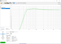
So to clear the air, I thought we could play the Impedance plot game:

Rules:
Maximum 2 sweeps per graph.
Phase is included, but if graphs get too busy, I can remove them.
1 Logarithmic Y scale MUST be included (allows one to view high and low values simultaneously)
A zoomed in trace may be requested (optional)
No red/green traces please (for our red/green colour impaired friends)

Winners:
Correctly guesses the reason for the difference between the two traces. Close enough is good enough...

GOLDENEYE award- correctly understands the difference between the two traces.

SCIENTIFIC COMMUNICATOR AWARD - explains why, in lay terms, for the differences, so that we can all follow along.
eg. "This trace is a of a subwoofer, because of the peak in the graph is at a low frequency ie. 23Hz. Is it a very high peak, because... . The double peaks and the saddle in between them at 38 Hz suggests that this is.... The discontinuity at ~170Hz suggests either... however we need more information on the..."

I'll be adding to this this list as I collect more. Please feel free to add your own for the diyAudio brains trust to help solve your impedance plot problems... Remember, the only way to learn is to make mistakes. So feel free to have a go!

First up:

1710944212629.png

GOLDENEYE! for @PKAudio's post. How did he do it? Any Scientific Communicators among us?
previous Leading scorer: @stv, partially correct on both traces. very close- please try again!

ITEM 2:
1710947651783.png


GOLDENEYE award to @mbrennwa . Yes, correct on all counts. But why only possibly in a sealed box? Was there any doubt? And why/why not? What happens when one omits damping?
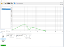
ITEM 3: courtesy @Hörnli
1711027123797.png


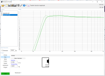
ITEM 4: same product, different samples.
1711027101929.png

1711082736618.gif


2nd graph courtesy of John Krutke

ITEM 5: Coming up....

PS. Once you win a prize, please go to the end of the line and wait for other people have a go. Better yet, post your own confusing/tricky plots for us to play/learn from....
  • Like
Reactions: Arez and stv

first power supply build

Hi
I've done some calculations and think they're right, I want to build a 5v 5A power supply. So my parts are a 230v toroidal with 2 12v 6.6A secondary outs. I'll only be using one at the moment. so the 12v 6.6a goes into a rectifier then 2 4700uf caps and a 1uf ceramic cap all parallel, then a 5v 5a regulator then the same caps again then a 1k resistor for bleed.
are my calculations way out or should this give me a decent linear supply?
another question is what awg wire can handle 7-5 amps? is 22 too low? what about 18? i keep reading things and can never get a definitive answer.

Should you buy speakers with ferrofluid tweeters?

Should you buy a commercial speaker with a ferrofluid tweeter or not? I read lots of cases where the ferrofluid corrupts with age and I don't fancy taking on the problem of cleaning and replacing ferrofluid in a tweeter.

I have a pair of early Wharfedale speakers Program 30D-6 and I have no idea if the tweeter has ferrofluid in it or not - can't find any info. I was thinking of buying a later pair, like the Diamond 9.1, but the tweeters do have ferrofluid in them and I'm concerned that this will degrade with age.

Given that ferrofluid deteriorates over time, should one simply stay well away from tweeters containing it?

Cambridge Azur-851W schematic or service manual needed

Got a Cambridge 851W in for repair from a friend. It goes directly into Protection mode when switched from Standby to On.
LED flashes 4 times indicating DC on output, but no DC to measure on output relay contacts...
Seems to be a fault in the Cambridge CAP5 protection system (quick search on Google indicates that this CAP5 system is highly unstable).
Anyone??
Thanks in advance

RH Labs SB-3p Help

Hello,

I am trying to save this classic passive subwoofer.

RH Labs SB-3p with Pyle 12” W12C600-F

I will refoam the speaker.

The crossover needs help. The coils are disconnected.

I believe this is a 1 way crossover with L-pad.

Can anyone help me solder the resistors back where they belong?

I’m hoping the pros here will be able to take one look at this set up and point to the solution.

Thanks a bunch,
Dane

Photos of terminal board, driver, and circuit attached.

https://photos.app.goo.gl/78repHM1zyMQZPK46
https://photos.app.goo.gl/6Lv23wxFGVpmBJcy5
https://photos.app.goo.gl/2Fu5QMjvmtqWjtYw9

IMG_1294.jpeg

Where to place the clock for a DAC

Hi
I would like to try building a DAC using an R2R Ladder board, you can get them on Aliexpress and Audiophonics. the one I'm looking at has bck/lrck/data/gnd inputs.
My question is should the iancanada reclocker fifopi Q7 be connected to the output side or the DAC board side? I was thinking of having a transportpi mk2 on the output and a recieverpi pro 2 on the DAC board. But where should the clocks sit?
cheers

Transformer Seat - Horizontal orientation over chassis plate "Lip Up" [3D Print]

As of 10/11/24 I have 3 transformer seats available to give away. I will update this post as they are snagged up. I'm offering up a free 3D printed seat for interested persons as long as shipping label is sent to me. 2 quantity limit per person please. Works with both 300VA and 400VA Antek transformers (or similar dimensions).

I can ship these to anyone interested as long as you pay for shipping by sending me a shipping label. To make it slightly more enticing, I'll also include a few other fun 3D printed parts you can use in builds in the shipment. Please PM me for details on how to create a shipping label. The goal is to give these away with no monetary transaction required, just a shipping label PDF and I'll pack it all up and send it out. Please let me know if you plan to use this with a 4U or 3U chassis and I will tailor the 3D print design I send respectively. They technically can be used for either option, but each print can be set up for the ideal use (still modifiable for other chassis with a careful Xacto knife cut).

20240324_201242.jpg


----------------------------------------------------------------------------------------------------------------------------------------------------------------------
Here's the "funny" transformer seat I used to horizontally mount an Antek 300/400VA over the "lip up" on a Modushop 4U chassis. For "Version 2" I've added a second slot to use for 3U chassis so you can pick how close you want the transformer to be to the front panel. There are two options as there are two slots. I suggest you use supports to "plug" the slots with support structure, then simply use an Exacto Knife, or similar, to remove whichever slot you intend to use. This ensures the part overhanging the lip has minimal sag.

The part was designed to be printed with the "compliant and squishy" TPU material (thermal polyurethane). However, PLA (much harder) could be used with the included rubber gasket that transformers come with as an interface between the transformer and the seat.

I designed this to allow "lip up" orientation while keeping the transformer as close to the front panel as possible by simply raising the
bottom of the transformer up ~10mm off the pate using the seat. If you install the bottom perforated plate "lip down", then there's no need for this part, but you still could use it for whatever reason you may have.

Attached are both *.STL and *.3MF files. You could use a "fab print house", however, I'd suggest finding a buddy (or buddies buddy) with a 3D printer, or use a Makerspace near where you live. Feel free to reach out to me with questions or suggestions. I'm open to feedback on how to improve and will keep the files attached to this message up to date with the latest revision.

Here's a link to see it in use (my first ever Firstwatt design build): https://www.diyaudio.com/community/threads/firstwatt-aleph-j-zen-mod-edition.410644/


1711172396302.png


1711172420951.png


Here's the start of a print in TPU, just after first bottom layers have finished and the "gyroid" 15% infill has started. Note that I blocked support for the inner most slot but left support for the outter most slot. This ensures if you choose to use the inner most slot (for a 3U chassis), the outer most slot essentially does not exist as you leave the support structure in place. The whole purpose is to avoid a 'floppy' overhang off the plate and therefore still provide some 'support' even though that portion of the 'seat' is cantilevered in free space.

20240322_225456.jpg

Attachments

4 stage Amplifiers Sansui vs Pioneer A70

The aim of four stage amplifiers was to offload the gain profile of the LTP to an assistant second gain stage before the main stage, the requirement of the assistant second gain stage was that it was to have virtually no distortion of its own and have a substantially lower gain than the LTP. With the A70 the second stage is coupled to the main gain stage almost as a current mirror, while SANSUI uses self cancelling. Here's my rendition of what SANSUI was aiming for https://www.pcbway.com/project/shar...audio_power_amplifier_a_rebirth_4a7881e9.html, while for reference is the A70. Are these better than the 3 stage Morpheus? https://www.diyaudio.com/community/threads/morpheus-ultra-low-thd.406485
3D_PCB_SANSUI_legacy pro_2024-03-21.png

PioneerA70.png
  • Like
Reactions: ZoltanChivay

What Ge Transistors are these?

Could someone tell me what Ge's these are/who/where they were made?
And hopefully what the values written mean too?
Background:
I have two spare Ge transistors (plus some resistors) given to me in bags by the bloke who modified the Dunlop FuzzFace JH-2 i bought 13yrs ago. The Ge's that were and are still in it are a NKT275 and a B175.
Could someone tell me what these SPARE Ge's (see pics)are/where were these manufactured, and what the values mean? (see pcs).
Q1 and 2 obviously each Transistors' place, but I think 'L' = leakage or gain?
The markings on each spare Ge ive written on the note (see pic).
The Ge's that were and are still in it see pics.
1st pic is spare Q1,
2nd pic is spare Q2
3rd pic is the values of these spare Ge's, or maybe the spare resistors i was given.
4th pic is the engravings on each of the two spare Ge's,
5th pic is underside of spare Ge's (both the same),
6th pic is top of spare Ge (see 4th pic for engravings),
7th pic is the Ge's that were in it when i bought it (1x NKT275, 1 x B175),
8th pic are values written on inside FzFce base plate for Ge's NKT275, B175 i assume.
Thanks.

Attachments

  • A0E1FA06-9460-43EA-B3C0-3DB15F006FE4.jpeg
    A0E1FA06-9460-43EA-B3C0-3DB15F006FE4.jpeg
    495 KB · Views: 96
  • FFDD525B-402D-4F54-B6DC-8BC9588C273C.jpeg
    FFDD525B-402D-4F54-B6DC-8BC9588C273C.jpeg
    485.7 KB · Views: 106
  • 3E206250-FE9B-4BFD-9285-7923D8C6E434.jpeg
    3E206250-FE9B-4BFD-9285-7923D8C6E434.jpeg
    515.1 KB · Views: 102
  • 1C43425F-1B56-4B94-9572-9F41D927D4EE.jpeg
    1C43425F-1B56-4B94-9572-9F41D927D4EE.jpeg
    282.4 KB · Views: 97
  • A7A8B0EF-5025-49A9-89AE-76D342AB2824.jpeg
    A7A8B0EF-5025-49A9-89AE-76D342AB2824.jpeg
    231.3 KB · Views: 110
  • 39173716-8A84-4B4F-A121-53E531F8F01D.jpeg
    39173716-8A84-4B4F-A121-53E531F8F01D.jpeg
    241.4 KB · Views: 107
  • 4899CE9A-2C41-4190-9B98-AE14771816F5.jpeg
    4899CE9A-2C41-4190-9B98-AE14771816F5.jpeg
    413.3 KB · Views: 115
  • CFB3956A-2F32-4C0C-B701-BBBA2FE1B5BF.jpeg
    CFB3956A-2F32-4C0C-B701-BBBA2FE1B5BF.jpeg
    788.8 KB · Views: 108

Mixed Semiconductor Output Stage

Like it says on the tin.

Been looking at all kinds of transistors from bog standard BJT to RF HEMT. From my understanding, configurations like darlington, sziklai (can never remember the spelling of that), and composit amplifiers allow you to mix and match properties of different semiconductors in order to get better overall functionality. Is it worth looking into this further, or should I just stick with one set of transistors? If it is worth it, I would really appreciate some part recommendations. While I understand there's a few gold standard parts (Toshiba transistors for example) I'm sure there are a lot of others out there that may not be as prevalent because they are not used typically for audio, but can still perform as well if not better.

Crown 5002VZ

Hi everyone, have an issue with my crown 5002vz. Upon power up channel 1 signal light is stuck on and odep is off. Channel two is in normal state.

I open d top lid and the ch1 DC/LF light indicator is on along with with d stand by.

Once in a while when it put it on both channels come in to normal state and plays well. But sometimes channel one doesnt click in

Did anyone ever encounter a problem like this? And does anyone know what could be the issue.

One guy told me it could be the output modules started to get defective, corrosion. I know these crown 5002 n 5000 output modules are susceptible to corrosion. But this particular one the output modules are clean.

So if anyone has any idea what could be to issue, please let know TIA

~~~~K20

Intact Audio 1:1 transformers in an Audionote Kit DAC 4.1

Today I replaced the origina 1:1 interstage transformers in my Audionote Kits DAC 4.1 with a couple of 80% Nickel cores custom build by David Slagle (Intact Audio).
The upgraded transformers are a bit bigger than the original ones, but I was able to make them fit quite easily.

The results are quite impressive in terms of wider/deeper sound stage, more clarity in particular on the top end where the DAC 4.1 with the original 1:1 transformers sounded a bit edgy and fuzzy, and in general the music sounds more fluid.

I am really happy with them and I would suggest the same upgrade to all the owners of an Audionote Kits DAC, together with replacing the coupling capacitors with Duelund CAST PIO Cu/Sn.

My next upgrade will be replacing the AN1865 DAC board with a AN1862 one.

PXL_20240322_204559587.jpg
PXL_20240322_214923302.jpg

Digitech G300 as home audio amp

im thinking of buying a digitech g300 mosfet guitar amp---technology by hafler--- for my home music system, but i dont know anything about this amp.....would a guitar amp suitable for home audio??it has 1/4 " plugs on back...could these be converted to rca type plugs? input imp. is 100k ohms. input sens. is 600mv for 150 w @ 8 ohms. im not sure if this info is vital or not! anywho, any feedback is welcome!! thanks ..shallenn

Passive whole and split RIAA networks calculator.

Working on a split RIAA networks eq, I used this old spreadsheet of mine.
I couldn't find on the net (not even here) any formula which keeps into account the effect of the input impedance of the stage following a network. This calculator does.
I work with LibreOffice. The .zip file here attached contains both the original .ods spreadsheet and its translation into a .xls.
I wish to share it, perhaps it can be useful for some of you.

Attachments

WinISD showing over-excursion for manufacturer's recommended box size

Hi, I'm new to building speakers and recently decided to make a new box for the subwoofer for the existing 2.1 speakers(JBL creature III). The old subwoofer driver had torn its surrounds and therefore decided to make new one.I am not making something very loud but rather flat sounding. I went for dayton ND140 5.25" 4 ohm driver (https://www.daytonaudio.com/product/57/nd140-4-5-1-4-aluminum-cone-midbass-driver-4-ohm) in a vented box. The driver is rated for 40watts (although my amp can do max of 15 watts), 4mm Xmax, 20mm peak to peak. The manufacturer recommends 1cu ft box with F3 of 34hz (parts express says 0.75cu ft with F3 41hz) but when I was designing the enclosure in winisd , it showed that the speaker was already hitting Xmax at 15 watt in a 0.75cu ft box. Increasing box size only makes it worse. I came across several reviews where the driver was put into 1cu ft boxes and worked flawlessly but i couldn't figure out how was it working for them if its already way beyond its xmax limit. Could someone please help me with this.

Attachments

  • 0.7cuftex.png
    0.7cuftex.png
    23.8 KB · Views: 72
  • 1cuft.png
    1cuft.png
    25.1 KB · Views: 75
  • 1cuftex.png
    1cuftex.png
    23.8 KB · Views: 77
  • 0.7cuft..png
    0.7cuft..png
    23.7 KB · Views: 78

Walrus BOW tech mosFET amp issue

Got this beast. Left channel failed, two mosfets blown. Driver mosfet source resistor blown but mosfet seems to be ok. However the circuit looks a bit odd to me.. power mosfets are capacitor coupled to the driver stage like tube anplifier. What do you think about this one? I made a quick schematic of the power and driver stage.

Attachments

  • IMG_20220718_093245.png
    IMG_20220718_093245.png
    1.1 MB · Views: 514
  • IMG_20220718_093256.png
    IMG_20220718_093256.png
    1.1 MB · Views: 379

Overview DIY/Refurbishing/Upgrade Record Player/Turntables - Ideas and Part-Suppliers (Bearing-Spindle-Platter)

Overview DIY/Refurbishing/Upgrade for Turntables - Ideas and Delivery Sources for Bearings, Spindles and Platters

Realized Ideas (for getting more easy decision making of own projects)
http://www.troelsgravesen.dk/maglev.htm
https://teresaudio.com/project/index.html
https://thewoodwhisperer.com/viewer-projects/steves-diy-turntable/
https://diyaudioprojects.com/Phono/DIY-Turntable/
http://srm-tech.co.uk/NEW-SRM-TECH-AZURE-DIY-TURNTABLE-USING-REGA-PARTS-JUST-ADD-ANY-REGA-DECK
https://www.hifipig.com/an-awesome-diy-turntable-build/
https://attitube.com/diy-record-player/diy-record-player/
http://www.altmann.haan.de/turntable/
https://www.stereonet.com/forums/topic/240229-diy-linear-tracking-turntable/
http://www.pyonsound.com/home/product2.php?mode=read&mod_gno=27
https://web.archive.org/web/20080311112503/http://www.straceny.de/Plattenteller/plattenteller.html
https://web.archive.org/web/20071225125802/http://www.straceny.de/Kontakt/kontakt.html
https://www.pinterest.de/pin/629941066613695160/
Login to view embedded media https://www.pinterest.de/pin/my-diy-turntables-and-diy-tonearm-diyaudio--72409506478759546/
https://www.pinterest.at/pin/224194887680849405/
https://hackaday.com/2015/03/09/diy-turntable-in-a-beautiful-wooden-case/
https://www.theanalogdept.com/diy_turntables.htm
http://diyaudioprojects.com/Gallery/displayimage.php?pid=306
https://www.instructables.com/DIY-Record-Player/
https://commons.wikimedia.org/wiki/File:DIY_turntable_by_J.C.Mills_2.jpg
https://www.lencoheaven.net/forum/index.php?topic=26332.0
https://www.diyaudio.com/community/threads/diy-turntable-build-with-motor-and-controller.380345/
https://www.electronicbeats.net/the-feed/learn-the-hidden-art-of-building-an-elite-turntable/
http://rkheck.frege.org/audio/turntable.php
https://www.diyaudio.com/community/threads/new-diy-turntable-project.325024/
https://www.diyaudio.com/community/threads/diy-turntable-plans.377354/page-2
https://www.diyaudio.com/community/threads/diy-turntable-build.341885/
https://www.diyaudio.com/community/threads/new-thread-my-diy-turntable-plan.9367/
https://www.diyaudio.com/community/threads/here-my-lartest-product-of-a-diy-turntable.246015/
https://www.diyaudio.com/community/threads/diy-turntable.3782/
https://www.diyaudio.com/community/threads/oracle-motor-controller-problems-diy-turntable.116373/
https://www.diyaudio.com/community/threads/a-diy-turntable-project-from-turkey.165098/
https://www.diyaudio.com/community/threads/diy-vpi-based-turntable.185469/
https://www.diyaudio.com/community/threads/another-diy-turntable-and-tonarm-project-journey.91505/
https://www.diyaudio.com/community/threads/the-official-turntable-drive-system-motor-thread.176077/
https://www.analog-forum.de/wbboard/index.php?thread/149661-diy-masselaufwerk/
http://www.hifi-forum.de/viewthread-26-27053.html

Tonarm DIY Projects
https://www.diyaudio.com/community/threads/diy-linear-tonearm.238027/
https://www.diyaudio.com/community/threads/diy-schroeder-tonearm.13372/


Parts like bearing/spindle sets and platters for DIY and upgrade of old ones

Suppliers
http://www.akamaiaudio.it/17-turntable-parts?id_category=17&n=45
http://www.akamaiaudio.it/spare-par...ndle-with-clamping-platter-system-deluxe.html
http://srm-tech.co.uk/epages/4c0089...923-2265-416e-a207-cc9dd8b06028/Products/SSP1
https://www.ebay.com/itm/393906239672
https://www.vinylengine.com/turntable_forum/viewtopic.php?t=117850
https://www.arche-headshell.de/acce...y-most-effective-upgrade-for-every-turntable/
http://www.robyattaudio.com
https://www.acoustic-signature.com/technology/dtd-dura-turn-diamond-bearing/
https://www.schopper.ch/index.php?page=restoration-main-bearing-9012
https://www.peakhifi.co.uk/cgi-bin/ecom.cgi?Command=ShowProduct&db_pid=582
http://www.fidelitydesignsltd.co.uk/cusbearings/cusbearings.html
http://store.diyhifisupply.com/index.php?route=product/category&path=239_237_177
https://www.diyaudio.com/community/threads/sourcing-diy-turntable-parts.382439/
https://web.archive.org/web/20010701000000*/http://www.scheu-analog.de (for finding NOS parts)
https://web.archive.org/web/20010406182407/http://www.scheu-analog.de/Preisliste/preisliste.html

Tutorials
https://www.diyaudio.com/community/threads/diy-turntable-spindle-bearing-tutorial.270021/
https://www.diyaudio.com/community/threads/measuring-the-quality-of-diy-turntable.341411/
http://www.johnclarkemills.com/2008/05/12/sourcing-parts-for-the-diy-record-player/
https://www.vinylengine.com/turntable_forum/viewtopic.php?f=18&t=38610
https://www.vinylengine.com/turntable_forum/viewtopic.php?t=90650
https://blog.gntech.se/en/projects/turntable/cutting-the-platter-and-bearing-seat/
http://www.vinylengine.com/turntabl...&t=21055&sid=a07786f8056cb3b1890c9b49041fcf0c

Magnetic Turntable Bearing
https://www.diyaudio.com/community/threads/magnetic-turntable-bearing.96655/
https://www.turntables.lt/en/platter-with-magnetic-bearing/
https://destiny-audio.com/products/ffyx-60mm-aluminum-plate-maglev-bearing-for-diy
https://forums.stevehoffman.tv/thre...design-can-it-be-used-for-turntables.1011074/
https://www.pinterest.de/pin/507499451750752445/
https://www.diyaudio.com/community/threads/magnetic-turntable-bearing.96655/
https://www.trans-fi.com/salvation-updates
https://theaudiophileman.com/tranquility/
https://www.hifiaf.com/tiger-paw-tranquility/

Bearing/Spindle for various Brands
LENCO
https://www.lencoheaven.net/forum/index.php?topic=2022.0
https://audio-creativeshop.nl/lenco-refurbish-and-restore/
Thorens
https://www.woodsongaudio.com/service/thorens-td124-main-spindle-bearing-rebuild
https://www.theanalogdept.com/td124_bearing.htm
https://www.riversideaudio.ch/english/restorations-repairs/main-bearing-rebuild/
https://www.theanalogdept.com/td_platter_bearings.htm
REGA/Pro-ject
https://www.analogueseduction.net/p...ies/pro-ject-platter-bearing-replacement.html
https://www.henleyaudio.co.uk/products/Platter-Bearing
https://www.acoustand.co.uk/collect...ter-upgrade-for-pro-ject-xpression-turntables
Garrad
https://audiovault.ca/product/garrard-changer-platter-bearing/
https://www.artisanfidelity.com/leg...rence-bearing-and-stainless-steel-platter-set
https://www.positive-feedback.com/Issue32/garrard_bearing.htm

Technics SU-G90 no display or sound

Hi!,
This unit had intermittent output and I tried to help a friend by expecting to find dry joints. I found a few, but the fan was not working so while I was tracing the circuit my hand slip and I now have no display or audio. I have voltage on pin 4 60volts and lights on the function buttons. Q705 transistor seems to run hot as the circuit board is discoloured. I have no schematic and would appreciate any help I will give more info if needed. Looking forward to someone pointing me in the right direction.
Thank you
Tony

Mission Cyrus two - assistance pls -Adelaide Oz

Hi all. New on here. Have a basic understanding of electronics.........
So.......have settled on Mission Cyrus gear for a new living room.
Have come about a Mission Cyrus 2 with one faulty channel. The previous owner tells me he had it repaired recently but has failed again and they replaced a transistor....presuming an output transistor??
I am seeking some advice -
1. Trying to find a Service Manual/Diagram for the Cyrus 2 and PSX (need to check what has been done/replaced previously as seeking to restore -not mod). Have done a search and either hitting multiple broken links or sites no longer accepting registrations, eg Hifiengine, etc; and
2. Any suggestions of someone who can assist in doing the technical work.....ideally in Adelaide SA (but not necessarily)
TIA

MA Audio HC4002 Class AB amp in protect mode

Can anyone help me figure this amp out? So a friend of mine has had this amp sitting around for 17 years since it stopped working. I know there have been two people before myself that have had this amp open and tried to get it working again. The only thing I can see that has been done is someone has tried repairing a trace that wasn't broken but looked as if it were. I myself have replaced the RCA input and outputs as I noticed they had been broken once before and someone tried soldering the break I replaced it with a new one. Then the switch for the LPF HPF and Full was broken off at the black plastic knob part so got a new one of those on it. The amp powers on and I even have audio coming out of it but without power. I can't find much more than a few pics online of this amp. Owner says he remembers the status light on it being green when it was operating fine led is now red. Both fans kick on immediately upon it switching on, owner couldn't recall wether this was the same under normal working conditions. This amp has 8 irfz44's, 4 tip35c's and 4, 36c's all of which I have pulled from the board and seem to be good according to my meter tested on ohms as well as the diode setting. The amp also has a gl494 I'm guessing is the same as the tl494 I am unsure how this part of the amp would be working under normal conditions I have the readings from all 8 legs while the amp is on at 12.1v and 5 amps. Not sure where to go from here...

Linn LK100 no sound

Hiya all
Working on a Linn lk100 and it seems to be stuck in protection..
The left channel had blown output transistors. Replaced them. Nothing else downstream seemed out of spec but yet no sound. Measuring at the DIS point shows me -30v which from what I read is the protect kicking in. I've removed the board and reflowed much of it but now I'm kinda stumped? All my rail voltages are good as well.

Attachments

  • ooRexQ8.jpg
    ooRexQ8.jpg
    115.8 KB · Views: 145

BSR EQ-3000 - Constant Hum

I have a BSR EQ-3000 that I've had for 10+ years and worked great - been in the family since purchase in the 80's, maybe early 90's. In the last few months it developed a loud hum when connected to vinyl input. Tried different audio cables, input, etc. - chased the hum to the BSR.

I opened it up to take a look to see if anything jumped out at me, and these 2x 470 micro Farad capacitors look melted to the PCB - does this look consistent with the issue? Can't decide if its worth it to trouble shoot or dump it and replace.

Feel free to hurl insults or insight.

20240317_195811.jpg
20240317_195800.jpg

For Sale 3E audio TPA3255 EAUMT-0260-2-A excellent shape!

Selling a older generation 3E AUDIO TPA3255.
EAUMT-0260-2-A
Rev 1.0 3
1. General Description
EAUMT-0260-2-A is a 2 channel (BTL) high quality class D audio amplifier module base on TPA3255.
Willing to trade for another Icepower 125asx2 300 series,any mid sized chassis maybe even Dac PCB finished such as older gen r2r etc. Im open to offers.

Or flat out sale 90 shipped USA Paypal

Attachments

  • IMG_0705.JPG
    IMG_0705.JPG
    492 KB · Views: 107
  • IMG_0706.JPG
    IMG_0706.JPG
    397.7 KB · Views: 110
  • IMG_0707.JPG
    IMG_0707.JPG
    494.2 KB · Views: 100
  • IMG_0708.jpg
    IMG_0708.jpg
    485.3 KB · Views: 120
  • IMG_0709.JPG
    IMG_0709.JPG
    451.4 KB · Views: 105
  • IMG_0710.JPG
    IMG_0710.JPG
    460.1 KB · Views: 98
  • IMG_0711.JPG
    IMG_0711.JPG
    467.6 KB · Views: 109
Projects by fanatics, for fanatics
Get answers and advice for everyone wanting to learn the art of audio.
Join the Community
507,660
Members
7,883,063
Messages

Filter

Forum Statistics

Threads
405,974
Messages
7,883,063
Members
507,660
Latest member
AlvianSuryaAudio