Got a Cambridge 851W in for repair from a friend. It goes directly into Protection mode when switched from Standby to On.
LED flashes 4 times indicating DC on output, but no DC to measure on output relay contacts...
Seems to be a fault in the Cambridge CAP5 protection system (quick search on Google indicates that this CAP5 system is highly unstable).
Anyone??
Thanks in advance
LED flashes 4 times indicating DC on output, but no DC to measure on output relay contacts...
Seems to be a fault in the Cambridge CAP5 protection system (quick search on Google indicates that this CAP5 system is highly unstable).
Anyone??
Thanks in advance
I would contact Cambridge Audio;
https://techsupport.cambridgeaudio.com/hc/en-us/articles/200930032-Azur-851W-Manual
https://techsupport.cambridgeaudio.com/hc/en-us/articles/200930032-Azur-851W-Manual
Is the CAP5 circuit for each channel mounted on two small PCB's mounted vertically with their solder sides back to back? That's how it is on a 640A V2, and I was also experiencing strange protection issues. If so, remove any foam that may be between those two small boards, since it can become conductive over time and cause the CAP5 to misbehave.Got a Cambridge 851W in for repair from a friend. It goes directly into Protection mode when switched from Standby to On.
LED flashes 4 times indicating DC on output, but no DC to measure on output relay contacts...
Seems to be a fault in the Cambridge CAP5 protection system (quick search on Google indicates that this CAP5 system is highly unstable).
Anyone??
Thanks in advance
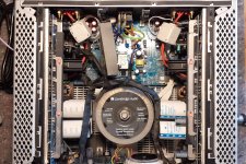
This is how the amplifier is build up.
When switched On and while indication in Protection mode, there are no DC power to the output stages.
All output transistors measures ok (measured in circuit).
All fuses checked.
I can't seem to locate the CAP5 section though......
When switched On and while indication in Protection mode, there are no DC power to the output stages.
All output transistors measures ok (measured in circuit).
All fuses checked.
I can't seem to locate the CAP5 section though......
Attachments
Last edited:
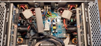
Without a schematic to refer to, I'd be guessing at where the CAP5 circuit is. BUT if it's anything like the 640A V2, it might be the two boards I'm pointing to in the attached. Obviously the foam I mentioned wouldn't be the issue, since the boards aren't mounted back to back like in the 640A V2.

Thanks and also my guess.....Without a schematic to refer to, I'd be guessing at where the CAP5 circuit is. BUT if it's anything like the 640A V2, it might be the two boards I'm pointing to in the attached. Obviously the foam I mentioned wouldn't be the issue, since the boards aren't mounted back to back like in the 640A V2.
View attachment 1031902
So I really need the schematic or the service manual
First post here, thank you all for having me on board.
I am watching this thread with interest as I have an 851W with similar symptoms, the only difference so far is mine gives 5 flashes (both channels) when trying to switch on from standby.
I removed the main fuses from one main board then the other to see if the problem was specific to one channel, but even with all fuses removed the flashing pattern is the same so I would conclude from this that the problem lies with something that is common to both channels rather than a fault with one or other of the amplifiers.

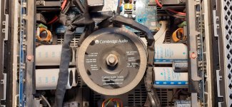
Are those white cubes on the output wires ferrite cores ?
The service manual can be downloaded from here registration may be required.Got a Cambridge 851W in for repair from a friend. It goes directly into Protection mode when switched from Standby to On.
LED flashes 4 times indicating DC on output, but no DC to measure on output relay contacts...
Seems to be a fault in the Cambridge CAP5 protection system (quick search on Google indicates that this CAP5 system is highly unstable).
Anyone??
Thanks in advance
https://www.hifiengine.com/manual_library/cambridge-audio/azur-851w.shtml

Thx !The service manual can be downloaded from here registration may be required.
https://www.hifiengine.com/manual_library/cambridge-audio/azur-851w.shtml
They hired engineering staff from Jaguar, I'm sure of it. I'm interested to get to the bottom of this too, there has to be a problematic component/bad matching - power? Wire? Heat related which then in turn affects the CAP5.
bonjour, c'est à mon tour d'avoir ce problème de protection défectueuse, une solution a-t-elle été trouvée ?
there are several relays and I wonder if forcing the closure of one or more relays will make it possible to do without these protections which are not working correctly????
octour34; Not here..... Totally bad designed amp so scrapped..... Did not want to waste time and money to repair it
- Home
- Amplifiers
- Solid State
- Cambridge Azur-851W schematic or service manual needed