Working on a split RIAA networks eq, I used this old spreadsheet of mine.
I couldn't find on the net (not even here) any formula which keeps into account the effect of the input impedance of the stage following a network. This calculator does.
I work with LibreOffice. The .zip file here attached contains both the original .ods spreadsheet and its translation into a .xls.
I wish to share it, perhaps it can be useful for some of you.
Attachments

I did some calculations on passive RIAA correction with input AC coupling recently, but had to resort to using an approximation. It works quite well when the DC bias resistor is placed right after the AC coupling capacitor, not so well when it is placed at the end (at the input of the next amplifying stage).
https://www.diyaudio.com/community/...eamp-phono-section-slp-70.407297/post-7557077
https://www.diyaudio.com/community/...eamp-phono-section-slp-70.407297/post-7557077
The schematic inside the spreadsheet is simplified regarding coupling the two stages. I did the same as you: the signal from the first gain stage crosses a coupling capacitor (2.2uF) whose right end is connected towards mass by the grid leak resistor; then the RIAA network follows, which is DC coupled both to the grid resistor on its left, and to the second gain stage on its right. So the second gain stage has its grid polarized towards mass across the RIAA network and you can neglect its virtually infinite input impedance when calculating the network.
Assuming zero reactance for the coupling capacitor didn't work at all unless it was 100 times or so as large as the RIAA capacitors. My approximation was pretending that the grid leak resistor is on the input side of the AC coupling capacitor, and applying a correction to the AC coupling capacitor's value (see chapter 3 of the document in the post I linked to).
Edit: I've attached the document and a zip with the document and spreadsheets to this post for convenience.
Edit: I've attached the document and a zip with the document and spreadsheets to this post for convenience.
Attachments
Last edited:
@MarcelvdG
I tried to understand, but I do not have enough skills to follow your calculations. So I understood the raw meaning of your thought, but no more than that.
I'm working on two passive split RIAA networks, and, contrary to the usual sequence, the 75µs follows the 318/3180µs network.
Both the gain stages driving one network each have a negligible Zout; pretend it to be around 10Ω, since it is driven by a buffer made out of a depletion mosfet IXTP01N100D served by a 15mA CCS (same mosfet). The mosfet shows a gm of 100mS in the worst case.
The Zin of the second stage is determined by the gate of a JFET (LSK489), which must be at 0V and needs a polarizing resistor lower than 150KΩ to prevent the JFET from oscillating. It is a bit more complex, but this is out of the scope of the speech.
For this reason, I chose a total R of around 100KΩ to polarize the gate, which is the sum of the RIAA resistor of 60KΩ, and 33KΩ right after the coupling C.
To determine the C I chose an Fc of 2Hz, low enough to prevent phase shifting at lower frequencies. So the C, with a 33KΩ resistor, comes out to be 2.2µF. The maximum Fc I could choose would have been 10Hz, but this does not work as a subsonic filter, so to stay as far as possible from phase shifting, I went for the 2Hz solution. If it makes sense to deal with phase shifting at so low frequencies. But even this one is another topic. Moreover, I will never use a subsonic filter made out of a feedback loop, so I renounced it.
I thought 2.2µF would have been a huge value to drive the 318/3180µs network. The 75µs network does not need to be decoupled, because it drives the output buffer which needs at its gate the same voltage as the source of the buffer driving the network.
But now you put the doubt in me, talking about a coupling C 100 times the RIAA C. Being not able to solve it myself, I'm asking you: please would you like to validate my values? I can fit (barely) a 4.7µF in place of the 2.2µF, just 100 times than the RIAA C. A bigger value would lead to a change brand of capacitors, but I like to use the ClarityCap CSA.
Thank you for your support!
Attachments
For the split network, the equations get a lot simpler, so I didn't need my approximation.
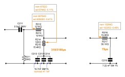
The 75 us network is simple: just make the time constant 75 us. Still, the annotated resistance doesn't completely match the parallel resistance of the two resistors and the time constant appears to be a bit too small, but maybe you corrected for driving resistance and/or loading capacitance.
The zero with 318 us time constant just requires the product of the capacitance of C212...C214 and the resistance of the parallel connection of R214 and R215 to be 318 us, which it is within a few tenths of a percent.
The difficult part is the pole with 3.18 ms time constant. Due to the coupling capacitor and the rounding, its time constant is actually 3.0979127 ms (which is within 0.1 % from the time constant of the two capacitors in series with the resistors in between them, 3.100806942 ms).
You can get the pole at the right place by increasing the resistance of R212 in parallel with R213 by about 1783.59 ohm, such that (R212//R213) + (R214//R215) = 69027.5917 ohm.
Mind you, I have assumed 0 source and infinite load impedances everywhere.
Last edited:
See also the attachments.
As you can see in the spreadsheet, I've been tweaking the subsonic roll-off to keep R211 at 33 kohm; you could probably just solve the equations with the value of R211 as a constraint and only the 3.18 ms RIAA time constant as a constraint, but I've been too lazy to do so.
As you can see in the spreadsheet, I've been tweaking the subsonic roll-off to keep R211 at 33 kohm; you could probably just solve the equations with the value of R211 as a constraint and only the 3.18 ms RIAA time constant as a constraint, but I've been too lazy to do so.
Attachments
The difficult part is the pole with 3.18 ms time constant. Due to the coupling capacitor and the rounding, its time constant is actually 3.0979127 ms (which is within 0.1 % from the time constant of the two capacitors in series with the resistors in between them, 3.100806942 ms).
When you let R211 approach infinity, that is, remove it, you can see from the schematic that any difference in voltage between the coupling capacitor and the filter capacitor damps out with a time constant set by the series connection of the coupling capacitor and filter capacitor and the filter resistors. Apparently R211 = 33 kohm is high enough to get within 0.1 % from the value for R211 approaching infinity.
Thank you @MarcelvdG , You are right. I think you will be always right, I imagine you as the "Black Knight" in this field. I still have difficulties to follow you.
When there was Latin Mass celebrated in some churches in Salt Lake City county, being Latin mother tongue (I'm Italian) I trained a priest in the Latin language and, besides the pronunciation training, I tried to explain to him some grammar. But I had to surrender, he didn't have the skill to understand in a few sessions what takes some years to be understood. So I took care of his pronunciation, made myself sure he understood, and gave him some light grammar remarks from time to time. It was my great satisfaction when he celebrated his first Latin Mass.
Here I'm the priest and you are the teacher, but your skill in math/electronic is far better than mine in Latin. Moreover, being 66, my brain is no more active than when I was 40.
I'm working on trying to understand the whole logic, but it is hard.
I had to stop now, I'm cooked.
However one more question for today:
You are talking about the 3.18 TC I found named Neumann. I also understood it is not needed since it acts like compensation for vintage equipment. So I removed it from my original design since it means the signal has to cross more components.
Do you think it is needed?
The so-called "Neumann" 3.18 microsecond time constant is not part of the official RIAA equalization specification. It has its advocates but is not needed in a properly designed RIAA playback circuit. The standard RIAA time constants (in microseconds) are 318, 3180. and 75.
I only mentioned the 3.18 ms = 3180 us first RIAA correction pole. Regarding the supposed Neumann pole, according to
https://en.m.wikipedia.org/wiki/RIAA_equalization#The_Mythical_'Neumann_pole'
it is one big misunderstanding, so no, I don't think it is needed. @ejp knows more about it, as he wrote that Wikipedia text.
https://en.m.wikipedia.org/wiki/RIAA_equalization#The_Mythical_'Neumann_pole'
it is one big misunderstanding, so no, I don't think it is needed. @ejp knows more about it, as he wrote that Wikipedia text.
@Ray Waters Thank you, I was almost sure this was to be omitted.
@MarcelvdG I must apologize, I misread your text. The exact conditions of my calculations are as cyan pictured in the attached schematic I just finished drawing.
@MarcelvdG I must apologize, I misread your text. The exact conditions of my calculations are as cyan pictured in the attached schematic I just finished drawing.
Attachments
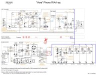
I think you overestimate the input capacitance of the T221 stage. If it had a loaded voltage gain of exactly 1, there would be no signal voltage across its gate-source capacitance (which is 98 pF typ. under datasheet conditions), so you would only see its (2 pF typ.) gate-drain capacitance. In reality, its gain is slightly less than 1, so you see the gate-drain capacitance plus a small fraction of the gate-source capacitance.
The calculations of post #7 only apply when C211 = 2.2 uF, but you can fill in other numbers in the spreadsheet of post #8.
The calculations of post #7 only apply when C211 = 2.2 uF, but you can fill in other numbers in the spreadsheet of post #8.
All you need to know about that is that what Wright described, or rather invented, isn’t a pole at all, it’s a zero. He didn’t use either word, but his graph goes horizontal at that point ;-) Complete fabrication according to Doug Self.Regarding the supposed Neumann pole
My bad, it is a common drain connection. Approximating Cin at 10pF, taking into account some parasitic capacitance on the PCB, the new R is 10392Ω, given by R221=16900Ω||27000Ω=10394Ω +0.02%.
About C211: a bigger C does not represent a problem to the driving stage, and will improve the coupling to the following network, I modified the PCB drawing to fit the 4.7µF, which have at home.
I received, as a gift, a 1975 Harman Kardon ST7 Rabco, one Shure V15 III, and one Micro Acoustics 2002-e. I had to fix the turntable tracking system, by replacing its o'ring square section, and now it is connected to a "Little Bear" which is a kind of toy for kids. So I'm looking forward to listening to the true sound of this stuff.
I just read the D.Self chapter about Neumann TC, and concludes: "The most popular cutting amplifier is the Neumann SAL 74B which has no such pole." Incredible how fake news affects also scientific topics.
I appreciate your help.
Which EQ should go first in a split RIAA nework?
I came to the conclusion, that in an active circuit that is sensitive to overload, the 75 µs pole should go first. This cuts the treble boost that otherwise could overload the first stage. Example is a transistor or two-stage operational amplifier circuit.
On the other hand, where noise of the active stages is an issue, the 75 µs pole should go after the main amplification. This cuts the noise of all preceding stages. Example is a tube RIAA preamplifier, where there is ample overload margin.
You are right. My schematic should guarantee a good overload margin, and since one goal of mine is to hear the silence when I switch to the phone preamp, I chose the tube-like sequence.
There is a diatribe about this topic between Fulvio Chiappetta and Diego Nardi in some "Costruire HiFi" Italian magazine. Chiappetta designed a tube preamp with the usual sequence, while Nardi used the tube-sequence in his design. My preference is for this second one.
All values in the schematic came from calculations, they are starting-points and need to be validated while live.
Moreover, I wish to push the gain to use an MC cartridge. but I don't know if it will be possible. This is the reason for the high voltage, the attenuator, and the Sziklai solution to raise the LSK489 transconductance, which is low. I want the loadline of the cascode/Sziklai to be as horizontal as possible. I will try to play with both the Rs and Rd and see. I excluded the solution with the bootstrapped follower because could increase the criticality of the stage, which is already critical in itself.
You would need a smaller gate stopper at the input for MC, it's already on the high side for MM. Maybe a high-loss ferrite bead?
When C211 = 4.7 uF, the combined resistance of R212, R213, R214 and R215 should theoretically be 68206.68186 ohm, assuming the other capacitors stay as is. That's without correction for the buffer output resistance. Keeping R214 and R215 as is to keep the zero at the right place, the parallel value of R212 and R213 would become 61462.1563 ohm, or 61452.1563 ohm when you subtract 10 ohm for buffer output resistance.
When C211 = 4.7 uF, the combined resistance of R212, R213, R214 and R215 should theoretically be 68206.68186 ohm, assuming the other capacitors stay as is. That's without correction for the buffer output resistance. Keeping R214 and R215 as is to keep the zero at the right place, the parallel value of R212 and R213 would become 61462.1563 ohm, or 61452.1563 ohm when you subtract 10 ohm for buffer output resistance.
- Home
- Source & Line
- Analogue Source
- Passive whole and split RIAA networks calculator.