Right, so time for an update on Teac drives and updating them.
I wrote in another thread on how to insert the cd tray into a CMK 4,0 drive, that I would be trying to use a cmk 3,2 drive in my very confined spaced Copland CDA-288 Mk. II S.E.
That is now done, and it can possibly be used elsewhere 😉
So here we go:
On my two Copland CDA-288, the Mk. I and the MK. II plus it's a special S.E. model with K selected BB PCM63 dacs instead of the normal BB PCM 63P, there's the good sounding CMK 4,0 drive, but I want to obtain a better output from the drive, before it enters fintering, conversion etc. So hence the wish to build in a CMK 3,2 Teac VRDS drive into the very confined space on the Copland CDA-288 cd-player.
This should in theory give a lot of advantages:
1/: better laser, glass kss151a. Improvement 1.
2/: magnetic drives laser sledge - fast and silent, and far more precise because it's not snail or tooth driven. Improvement 2.
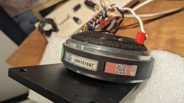
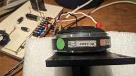
3/: big hall motor on the upper stable platter. Improvement 3.
4/: thick heavy cast aluminium upper stable platter. No noise from the cheap Mabuchi made in china brushed motor that bestows the CMK 4,0 drive. Improvement 4.
5/: a stable composite non-twistable upper bridge. Improvement 5.
6/: better upper bearing - larger, more precise. Improvement 6.
All this should in theory help with better output and mechanical stability/precision, which should lead to less errors and less error correction 😉
I bought (again, again, again) another VRDS-10 and used the servo board and the CMK 3,2 drive.
The connectors on the CDA-288 Mk. I and the MK: II S.E. are different in a very nice way: they became lazy at Copland in Copenhagen, and used some of the connectors directly from Teac. Well, to be honest, I don't know if they are lazy, they just did it. There could have been mechanical issues, production matters or other reasons. Anyway, it made it all the more easy to install the VRDS-10 servo board into the Copland CDA-288 Mk. II S.E. Thanks Copland! It fits right in and all connectors are ready.
The remaining connectors (most), are from the CMK 3,2 drive: laser, sensors, switches and hall bridge motor etc. Fits as well, as it all come directly from the CMK 3,2 driven VRDS-10.
So, on the Teac, the display sits below the drawer. On the Copland, it sits above the drawer. There is no way the CMK 3,2 will fit hight-wise and also in width. Hmm...
Fortunately a sanding of the underside of the lower composite plastic chassis is easy, use a mask, and it can be trimmed down.
Doing this, there are a few observation points, that have to be solved:
1/: the motor assembly that raises/lowers the lower center spindle, is mounted on to a metal bracket that is screwed down from above into the lower chassis. This make it hard to sand the chassis from below. Therefore I chose to alter the installation of said motor bracket to be as flat as possible, including cutting up threads to 4mm instead of Teac's 3mm, and use pinol stainless (un-magnetic) screws from below with a dab of 10-seconds glue to each (undoable/redoable). This solves that.
2/: the laser sledge lock mech have to be undone, by removing the white plastic tab. I will later on redo the small bracket and reinstall the laser lock tab, just in a lower, flatter version.
3/: the small flat laser cable transition pcb that sits under the lower composite chassis, have to be raised as much as possible. So I took off the standard stays and installed two new very low stays. Both 3mm screw versions. This raises the small pcb to lower the lower chassis that the whole CMK 3,2 drive can stay on 25mm stays and clear the bottom chassis plate on the Copland cDA-288 case.
4/: the next thing is to have a longer flat cable from the aforementioned laser cable pcb, to the Teac servo pcb. The standard used is 17cm long. I need at least 20cm to reach the connector on the servo pcb reliably. So I found that on fleabay. It works well, and the fresh lanes are most welcome.
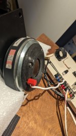
On the Copland, there are welded in some 30mm stays to support the CMK 4,0 drive from underneath. The two front ones must be cut off. I then installed two lower 24mm high 3mm bolt stays on the front edge of the CMK 4,0 metal upper chassis plate and when all else was finished, I gave them a dab of strong glue and installed the drive into the Copland case, waiting 24 hours for it to cure fully. The rear one to the left side is copper and makes a ground. This and the rear to the right are cut down to 24mm and drilled out and new 3mm thread cut, to support the modified CKM 3,2 upper metal plate chassis, which have to be drilled to suit the mentioned two stay on the rear. This is done by marking them with a dab of white tusch and install. Then lift the chassis and drill the upper metal chassis plate in the two spots now marked white. Finetune the stays in relation to the installed cd tray, before making it final, so the tray is centered in the opening of the front chassis plate on the Copland CDA-288.
Next is drilling a 10mm hole to support the HDCD led on the front of the Copland CDA-288. Then the connector can easily be installed/undone.
Then the sides of the upper metal chassis plate must be cut to suit and clear the Copland power supply pcb on the left and the Teac servo pcb on the right. A couple of corners have to be trimmed as well. I retained a few mountings points from the VRDS-10 sub chassis, so all it reversible. Also, new male-female stays in brass are ready to reverse the mods on the rear stays of the Copland CDA-288.
On the lower composite chassis, there have to be done a few trimmings on the sides as well, mostly where the chassis have protrusions to support the upper bridge. They can be angled and still fit well.
Next, the rearward right side spring have to be removed. It will still function well with only 3 springs.
Lastly, the right hand side of the button control logic pcb of the Copland CDA-288 have to be trimmed down a few mm's to clear the CMK-3,2 chassis.
That's all.
Of course, I have to retrim the laser to suit, as it's been handled around and need new precision adjustment. Just follow Teac VRDS-10 service manual, and it's done.
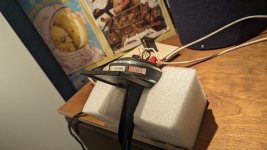
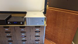
It plays! A CMK 3,2 drive is now working in a Copland CDA-288 Mk. II S.E. and is MUCH more precise and well working. I'll report back on sound quality etc, once everything is scoped and adjusted properly again.
Next up is an über bridge to the CMK 3,2 drive, which I feel can be improved a lot.
There are a few solutions to this:
1/: Either choose one of Teac/Esoteric's own solutions.
2/: Make your own.
As Teac actually did the bridges with a lot of precision, and it's slightly curved 0,5 degree, it's difficult for me to replicate the upper stable platter. So BRIDGE it is.
The later Teac/Esoteric Neo bridges and the last old series upper bridge have a construction that I can replicate. Thais can be done as long as I retain the CMK 3,2 upper platter as this has a certain weight and dimension.
Improvement 7:
I took the upper CMK 3,2 bridge apart and kept the hall (sony) motor coils as they are important. N need for voltage and amp changes then.
I then measured up the CMK 3,2 upper composite bridge and it's important dimensions: inner height to coils, spacing, drillings etc. A friend is now making a fat heavy stable aluminium one for me. It's only reinstalling the upper platter and the platter brake, and reinstall on to CMK 3,2 drive.
Improvement 8:
I also feel that the upper bearing which is a plastic grey cap and a dab of grease, can be improved. Note: the tightening of the upper 3 screws can determine the brake and resistance.
So, I made a design for a better top bearing, which uses a square top cap in metal and a bore that supports a ceramic ball. Less wear and more precision and less contact area to the spindle/top bearing relation. A ceramic ball is more round and wear less.
We'll see.
Improvement 9:
Green light has a dominant wavelength of 495-570 nm, and the Sony KSS-151a laser works at 781 nm. Hmm. Helpful? Let's try it. Green it is. So I want the upper platter to be green on the underside/cd side, to retain stray light or rather prevent the light that is not into a pit, be less seen and which is now out of phase and help the laser do a clean job. Less errors - less jitter. If one believes that.
I then wanted the Teac CMK 3,2 upper platter to be anodised green, but this led to a series of problems.
First, I looked at the metal composition of the VRDS CMK 3,2 upper cast aluminium platter, and it turns out to be involving a very high content of zink. As zink in this respect cannot take anodising, as I was told by two companies whom I contacted, I had to find another solution.
Painting is going to be worn off, so that is no good either and will also represent a whole problem in itself from a perfect flat surface perspective. No can do.
Traveling through every single VRDS drive ever made, some of the upper tiers are in fact green un the underside of the upper platter. Hey presto, get one of those. But they are not for sale. And to buy a Esoteric P2s just to use the upper platter is maybe taking it a bit far... Same goes for Teac P-70 drive. Same goes for Wadia 861SE which had an upgrade from CMK 3,2 to CMK 3,2s, also called Superdrive.
But hey, it happened to be so, that Wadia worked with Teac over a number of years, developing some of their pcb's and used some of their drives as we all know. But on The Wadia 861, one could order a Wadia performed upgrade to the drive itself. It was a 2500 usd option.. Mglp! It consisted of some vibration dampening cut to fit pieces of stick on material on for example the inside of the outer case, the upper metal CMK 3,2 chassis plate and more. And the other major difference, was the Superdrive! Hey, so there was originally a chance to get a Superdrive bridge and upper platter by order. As Wadia no longer exists, I had to scan the www to find one. And I did. This green upper platter is exactly what I was looking for, solving what I wanted to obtain nm wise.
Improvement 10:
I wan to obtain more stable rotational speed. On say a car engine, there is a flywheel. This acts as a stabiliser to the engine, so torque is retained better than with a light flywheel, which makes the engine pick up rotational speed faster. The exact same thing is the case with the CMK drive in our VRDS-drive cd-player. So I want more mass. I cannot make this myself though. But it would be nice to have, to obtain and keep a far more stable rotation in the rpm's that a red book reading does. More mass brings rotational stability.
On the Superdrive CMK 3,2s, is a far better upper plate in relation to stability. It is a better cnc made platter, rather than a cast low quality aluminium/zink thing. And it is heavier. Like on the CEC belt driven thing, the belt is not the only smart part. Rather the mass of the puck. Same here.
To improve on matters, Teac also made better magnets and an improved bearing, plus a stronger hall motor. I got what I wished to improve on.
Improvement 11:
On that Superdrive, there is a far bigger more stable well executed upper bridge and it will absorb and prevent vibrations from doing harm. More later.
Improvement 12:
On all my cd-players, there’s light from the outside slipping in through the load cd tray’s opening. I looked at Apple Mac Pro cabinet’s loading mec and unfortunately I couldn’t make it fit. It has a smart little door that closes the front opening so no light is entering. I will experiment with more solutions onwards. To prevent unwanted light from disturbing the cd reading. And Teac removed that window on the VRDS10se. And it came back later on, in form of Neo driven multi players…
Improvement 13:
Clock.
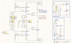
As with all things, matters can usually be improved and the clocks that Teac/Esoteric used in the old players, there are certainly things to be done. I installed an LClock XO and a separate power supply to avoid any transfer and get a precise stable clock.
Now, some years later, I want to get an even better clock, and lo and behold Larsen Audio made another much better version: LClock XO3, which have better shielding, lower ppm's (now 1!), and other improvements. Same power supply can be sued, so I'll do that, unless of course, I find a better one still.
Improvement 14:
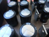
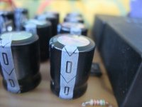
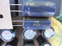
Capacitors.
I unsoldered the two most important ones in the signal path in the output stage and soldered in two bigger ones from Jantzen audio. It did take some hours to make them fully sing, but that made an improvement.
Improvement 15:
Chassis dampening.
To kill any unwanted vibrations, i cut a lot of bitumen sheets to fit inside the casing. I will improve on matters when I find something suitable thin for the upper chassis metal plate for the CMK 3,2 drive and it should work on the CMK 4,0 plate as well. More on that later.
Add: Well, I also now got a complete bridge and upper platter from a Esoteric P2s (not the P2). and the bridge is all metal (stiff) and the platter is cut aluminium with bronze inlay (heavy stable flywheel), and the underside is... green 😉 That will go into my other Copland CDA-288 with yet another VRDS-10 servo board and CMK 3,2 drive.
So far so good, and I'll be back with more later on.
Kind regards,
Redfox.


![PXL_20230508_182659685[1].jpg](/community/data/attachments/1080/1080220-66d1a7ac0fc3202ee705a9fe4ea93cd1.jpg?hash=ZtGnrA_DIC)
![PXL_20230508_182706822[1].jpg](/community/data/attachments/1080/1080221-d9da0beb47df4e2734e21c7429746e85.jpg?hash=2doL60ffTi)
![PXL_20230508_182704670[1].jpg](/community/data/attachments/1080/1080222-d887c2afc8b77aea82ffdfc8ad873810.jpg?hash=2IfCr8i3eu)


![IMG_1403[1].JPG](/community/data/attachments/1084/1084533-0da492a0f55a9558ca8ad67d6b407cd1.jpg?hash=DaSSoPValV)
![IMG_1405[1].JPG](/community/data/attachments/1084/1084534-357cd008600ecbe83c9bd362d40e7e01.jpg?hash=NXzQCGAOy-)