After good experience with development og DSP boards using ADAU1701 and using SigmaStudio for programming, I plan to take it a step further.
My plan is to make a board which can take up to 4 inputs and have 8 outputs.
This would be usable for specially a 3 to 4 way or a 4 channel amp. So actually I don't really need the 8 outputs, but it just seems codecs with 4 inputs also comes with many outputs.
Secondly I want it to relatively cheap to have manufactured.
I have with great success been using JLCPCB and their assembly service. Hand soldering DSPs and ADC/DACs is not that easy.
So it needs to be using components which are available at JLCPCB!
I you want a bit more DSP power, ADAU1452 seems a good bet. The same DSP is used in the freeDSP-aurora, so should be able to get some ideas from that.
For the CODEC I had my eyes on CS42448 , which promises -95 db THD+N in a single ended mode and - 98 db differential. It has 6 in puts and 8 outputs, and has what they call popguard technology to minimize pop noice at start up / close down.
But it does not really seem to be available anywhere.
Best bet seems to the the AD1939 which has 4 in, 8 out and delivers -94 db in differential mode, and is available at JLCPCB
Any other good ideas?
For optimal performance it is probably necessary to use active and differential filters on both input and output. This means 1 opamp for output and 2 opamps for input => 8 dual opamps.
I would like to be able to run it at +5V, so will need rail to rail opamps. OPA1642 is an inexpensive, but very high performance dual opamp at less than 3€ a piece.
Maybe I could use the DRV623 as output filter, eliminating the need for a muting circuit, but the THD performance is not as good as e.g. OPA1642 .... will that really matter?!
Programming should be via Wondom ICP (as this is what I have and as the connection is smaller then the USBi) and it only 20 USD.
I was considering whether to allow to balanced input, but not sure how to make an easy input circuit to allow for that and single ended without adding switches .... any good suggestions?
Power would be LM2596 (maybe as a finished module) + a number of LM317
Last edited:
Instead of the codec, we could use a combination of 2 x PCM1804 (3$/pcs) + 1 x PCM401 (9$/pcs) to achieve -102db in / -100 db out THD+N
Also an alternative filter opamp is the fully differential amp OPA1632, which can be used both at input and output at ca 3$/pcs ... for 4 in 4 out we would need 8 pcs
Also an alternative filter opamp is the fully differential amp OPA1632, which can be used both at input and output at ca 3$/pcs ... for 4 in 4 out we would need 8 pcs
That would be pretty cool! I think of the Dayton DSPB-K board (with DSPB-KE), but with more ins / outs. Esp if a solution could keep to approx that $ / channel.
https://www.parts-express.com/Dayton-Audio-DSPB-K-DSP-Kernel-Board-325-130?quantity=1
I don't like the MiniDSP software, I'd rather use Sigma Studio.
https://www.parts-express.com/Dayton-Audio-DSPB-K-DSP-Kernel-Board-325-130?quantity=1
I don't like the MiniDSP software, I'd rather use Sigma Studio.
Sure. The Dayton DSPB-K is the same as Wondom AMP2 board https://store.sure-electronics.com/product/AA-AP23122 ... only teh color is different.
These boards are really barebone ADAU1701 boards, using the ADAU1701's internal AADC and DAC. Especially the ADC leaved something to be desired with only -83 dh THD+N.
The aim with this project is to get both higher calculation power, more inputs, and better THD+N.
Whether I can keep the cost to the same level .... the DSPB-K + DSPB-KE is 31 USD and if I would have 4 in 8 out, which is double, it should be kept under 62 usd .... I think that is for sure possible
What triggered me really is a need for a multi channel 4-8 power amplifier with "separate" DSP on each to drive my surround channels. And I got inspired by the new L'Acoustics LA7.16i which is such a cool amp delivering 16 x 1300W with individual DSP capability .... my projects do of course not compare to this cool monster, but it's good to be inspired

Just did a few spec sheet comparisons of different ADC and DAC options.
Firstly the number you are presented with on the top line is the SNR or Dynamic range as this is always the biggest number 😉
What is more interesting is the THD+N. This is always described at full scale, that is just before clipping, as this is of course where all bits come into play.
But in normal use, you will seldom reach this level, and the THD performance will therefore be much worse.
Some also describes the THD+N at -60db (peak of signal 60 db below max). That is much more helpful. If this number was directly linearly deducible from the full scale number, it would not really reveal anything, but it seems there is not that simple a relation between the two.
Would have liked to have seen this for PCM5102A ..... would be nice if more companies would state this spec
Seeing something like -37 db ... which is the same as 1,4% is of course a bit concerning, and here is a point for those not liking digital .... you would not see this in a fully analog signal path 😉
It also shows that it actually does matter to optimize the performance of ADC and DAC and go for better THD+N numbers. If it was only the say -100 db THD you would encounter and hear .... well I would say no need, -90 db would be as good and you would no the able to hear the difference (btw. 0.001 % THD and 0.003%), but between -57 db and -37 db I would guess is something you could actually hear (0.14% and 1.4%)!
This also shows how important it is to design the chain from ADC to DSP to DAC so that the signal is as large as possible throughout the chain. I guess this is also why in a studio you have so many VU meters to monitor the levels, ensuring the level is high but that there is also a bit of headroom left.
So we need to ensure we chose the right input level to use as much the full scale of the ADC as possible, to have a large signal for the calculations in the DSP, and then again ensure we have the right level at the output to match the amplifier input. Her I think a resistor attenuator will be needed. But more on that later
Firstly the number you are presented with on the top line is the SNR or Dynamic range as this is always the biggest number 😉
What is more interesting is the THD+N. This is always described at full scale, that is just before clipping, as this is of course where all bits come into play.
But in normal use, you will seldom reach this level, and the THD performance will therefore be much worse.
Some also describes the THD+N at -60db (peak of signal 60 db below max). That is much more helpful. If this number was directly linearly deducible from the full scale number, it would not really reveal anything, but it seems there is not that simple a relation between the two.
| ADC | 0 dbFS | -60 dbFS |
| PCM1808 | -93 db | -37 db |
| CS5381 | -110 db | -57 db |
| PCM1804 | -102 db | -49 db |
| CS42528 | -100 db | -51 db (MiniDSP 4x10 HD) |
| DAC | ||
| PCM4104 | -100 db | -56 db |
| CS42528 | -100 db | -51 db |
Would have liked to have seen this for PCM5102A ..... would be nice if more companies would state this spec
Seeing something like -37 db ... which is the same as 1,4% is of course a bit concerning, and here is a point for those not liking digital .... you would not see this in a fully analog signal path 😉
It also shows that it actually does matter to optimize the performance of ADC and DAC and go for better THD+N numbers. If it was only the say -100 db THD you would encounter and hear .... well I would say no need, -90 db would be as good and you would no the able to hear the difference (btw. 0.001 % THD and 0.003%), but between -57 db and -37 db I would guess is something you could actually hear (0.14% and 1.4%)!
This also shows how important it is to design the chain from ADC to DSP to DAC so that the signal is as large as possible throughout the chain. I guess this is also why in a studio you have so many VU meters to monitor the levels, ensuring the level is high but that there is also a bit of headroom left.
So we need to ensure we chose the right input level to use as much the full scale of the ADC as possible, to have a large signal for the calculations in the DSP, and then again ensure we have the right level at the output to match the amplifier input. Her I think a resistor attenuator will be needed. But more on that later
Last edited:
Would it make any sense to design in an 8-channel volume control that mostly attenuates, so that the DAC can run at full bits all the time and the volume control is what is determining the distortion level? Of course this would add noise.
Hey Charlie
I think it mostly about designing the right level matching in. I would prefer to build in an analog volume control (pot meter) if this is what you mean.
The thought is to use this DSP after any pre amp, that is just before a power amp.
If we go for consumer levels we would have
https://en.wikipedia.org/wiki/Line_level
For consumer electronics I'm not sure there is a real standard or that the companies follow this!! It should be quite easy, e.g. if you know that Vp in is 1,095V and your power amp clips at say 65V, then you need a gain of 59,3 ......
As far as I can determine it goes like this
So what is important is that the input ADC would reach full scale at 1.095V, meaning 2.2Vpp, and the same goes for the output DAC.
We could ensure the DAC is able to give a max of 4Vpp and then attenuate with a pair of resistors to match either consumer or pro.
An important point here is of course that pro would be differential, so only requiring half the voltage swing per line.
If the DSP is put permanently into a power amp or a plate amp we would of course know what the power amps gain was which makes the matching easier.
I think it mostly about designing the right level matching in. I would prefer to build in an analog volume control (pot meter) if this is what you mean.
The thought is to use this DSP after any pre amp, that is just before a power amp.
If we go for consumer levels we would have
https://en.wikipedia.org/wiki/Line_level
For consumer electronics I'm not sure there is a real standard or that the companies follow this!! It should be quite easy, e.g. if you know that Vp in is 1,095V and your power amp clips at say 65V, then you need a gain of 59,3 ......
As far as I can determine it goes like this
| Vp | Vrms | ||
| Line Out Consumer (e.g. CD) | -10 dBV | 0.447 V | 0.316 V |
| Line in Consumer (Power Amp) | 0 dBV | 1.095 V | 0.774 V |
| Line in Pro | 0 dBu | 1.414 V | 1.000 V |
| Line Level Pro | +4 dBu | 1.736 V | 1.228 V |
So what is important is that the input ADC would reach full scale at 1.095V, meaning 2.2Vpp, and the same goes for the output DAC.
We could ensure the DAC is able to give a max of 4Vpp and then attenuate with a pair of resistors to match either consumer or pro.
An important point here is of course that pro would be differential, so only requiring half the voltage swing per line.
If the DSP is put permanently into a power amp or a plate amp we would of course know what the power amps gain was which makes the matching easier.
Another important point is also that you design the DSP program chain, that you try to keep the signal as high as possible all the time, meaning that it's no good to start with something which attenuate the signal too much, and applying gain further down the signal chain.
I actually found some more information on PCM5102A in the spec sheet, showing around -50db at -60 db input.
Question is how much the different parts will contribute to the overall performance. I think you add the different parts by taking the square root of the sum of squared parts. (think this is an approximation though)
So say we use PCM1804 as ADC and PCM4104 as DAC we would get (@-60db input):
-49db = 0.3548134
-56db = 0.1584893
Total THD+N = SQR( 0.3548134^2 + 0.1584893^2) = 0.38860 % = -48.2 db
But if we used PCM5102A as ADC with -50 db THD+N we would get
Total THD+N = SQR( 0.3548134^2 + 0.3162278^2) = 0.475281 % =46.5 db
Ok, not as good .... but the beauty about the PCM5102A is that it contains the output buffer and muting circuit, and therefore will require less space, cost and components
Attachments
I was more thinking of a ganged, actively buffered, adjustable volume control after the DAC, in the analog domain. This is not a new problem. People were already clamoring for such volume controls 10 years ago. It's a problem of balancing noise, gain, distortion, and getting good channel balance at all volume levels. Not such an easy task.Another important point is also that you design the DSP program chain, that you try to keep the signal as high as possible all the time, meaning that it's no good to start with something which attenuate the signal too much, and applying gain further down the signal chain.
Sure, know what you mean 😉 ... but if this is either for a build in dsp in a power amp or for a plate amp in an active speaker, I don't really think it is practical ... but for sure it would make it possible to adjust for higher performance ... but you have to fiddle with 2 volume controls all the time
Just read someone producing music saying that you can't really hear 10 x ADC-DAC 😉 ........ I don't know ... haven't tried.
But a bit of an eye opener is the ABX test og different codecs used for streaming music:
Using a Creative E-MU Tracker Pro sound card and Bayer Dynamix DT770 Pro headphones I could thell the difference bt. LAME MP3 128 kbps and uncompressed FLAC, but not when going to 256 kbps.
I have had my hearing tested a number of times (related to my work) so know it is not bad at all. Try it out yourself 🙂 http://abx.digitalfeed.net/
Anyway I have decided to settle on:
ADC: PCM1804
DAC: PCM5102A
DSP: ADAU1452
The use of PCM5102A is simply because I have good experience with it, it has a good muting function and does not require a buffer on the output, saving pcb space and cost.
I whish I was as fast as CyperPit at making the schematics and layout ... but I'm not and it will take a bit of time 🙂
... there will be many similarities to CyperPit's new excellent and brilliant design; https://www.diyaudio.com/community/threads/freedsp-octavia.393804/ so I will start by thanking him for borrowing bits and pieces from his design
I'm wondering still on how to make a pcb which would work as well for a plate amp as internally in a multi channel amp, and whether to include the input connecters directly on the board or an a separate maybe break off board (never tried to do one of those).
Also what input's to include. I will go simpler than CyperPit; thinking:
4 x Analog phono un-ballanced input + small terminal blocks
SPDIF, either Phono or BNC
TOS-Link, SPDIF
Output will be through bot small terminal blocks and U.FL Coax
Maybe someone have a good idea for how to incorporate LED outputs from the DSP??
With ADAU1701 it is super easy, and the chip included GPIO with LED driver capabilities directly. Not so with the ADAU1452.
I'm thinking that input and output peak LEDs would be useful
With ADAU1701 it is super easy, and the chip included GPIO with LED driver capabilities directly. Not so with the ADAU1452.
I'm thinking that input and output peak LEDs would be useful
I'm no help on the LEDs (or anything much circuit design wise) I'm afraid, but agree that input, output peak would be handy especially for the plate amp active speaker usage.
Simply offer my congratulations and encouragement... Great so see such amazing boards in development and gratifying that diy community members are collaborating with such generous spirit.
Simply offer my congratulations and encouragement... Great so see such amazing boards in development and gratifying that diy community members are collaborating with such generous spirit.
Ok, maybe I should read the data sheet, there is in fact a number (10) of MPx pins which can be used as input or output, if not used for any of the other purposes 😉
As mentioned, I'm trying to find components readily available at JLCPCB, also in high quantities so they do not run out. But I'm also truing to use what they call Basic component, in stead of Extended parts, as each extended part no will add 3 USD to the design in handling fee. .... that can add up to quite a lot 😉
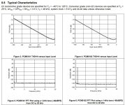
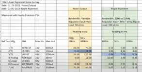
Trying to decide on regulators and found these 2 small videos where a guy is testing. LTV1117, LP2985, LM317, ADR4525, MC78M05 and NJM7805
Seems the guy really knows what he is doing, so think you can follow his reccomendations.
He found that the overall best performer is the M317 if you only count a noise BW of 20-20kHz!!!
There are probably much better LDOs, but probably also much more expensive.
Looking at this I think I'll just stick to LM317 .... cheap and good 🙂
Attachments
If using PCM1804 we need to have a full swing on input of +-2.5V centered around 2.5V.
If we are trying to use a single supply opamp on 5V, it of course needs to be fully rail to rail. How does the distortion look when we get near rail to rail I wonder?
I actually wonder why it's made this way! Would make much more sense if we could have full scale at say +-2V only ...
Even if we use +-5V using e.g. an OPA1632 as input amp, it will still have to reach +5V!!!
Any thoughts??
If we go with +5V only, then the OPA1642 seems like a very good choice at only ca. 3 USD
Rail to rail means 4.6V out with 5V supply, which is still close to full scale. Should be ok.
With 1.1Vpeak in, meaning Vpp = 2.2V (post #7) we need a gain of around 2x to get full scale.
See also this site and table ... note b means rail to rail
https://www.cycfi.com/projects/six-pack/op-amp-shootout/
Last edited:
- Home
- Source & Line
- Digital Line Level
- 4 in 8 out DSP using ADAU1652