and @Trileru Yes I saw that on Ebay. What about the DACs and ADCs? There needs to be multiples of each I think. Are there similar off-the-shelf boards for those that you can link to, e.g. having performance at the PCM5102 level, or better? If it is a matter of plugging several boards together and then applying SigmaStudio I might give it a try.I haven't gone down the PC route as mainly interested in the adau for live sound out and about. An adau14 system can be cobbled together with core board, pcm5102a / pcm1802 modules and a cypress programmer, 8x8ch for under $100, upto 20,000 taps capable.
Is that 1 Core ADAU14xx + 4 PCM5102 boards for 8x8ch?An adau14 system can be cobbled together with core board, pcm5102a / pcm1802 modules and a cypress programmer, 8x8ch for under $100, upto 20,000 taps capable.
I have a similar project for a battery powered DSP, the PCM5102A looks very interesting for reducing parts count. In my case the DSP needs a very wide single rail input voltage range for battery compatibility.The project had been stalled due to the parts situation but I notice the sigma DSP parts are beginning to be back in stock.
I think having such a wide range of possible configurations make it a bit more complicated. What configuration are you betting will sell best? How many channels etc?and @Trileru Yes I saw that on Ebay. What about the DACs and ADCs? There needs to be multiples of each I think. Are there similar off-the-shelf boards for those that you can link to, e.g. having performance at the PCM5102 level, or better? If it is a matter of plugging several boards together and then applying SigmaStudio I might give it a try.
Plus there's also the programmer issue. Do you include one? What presets do you load initially?
The chip itself has a bit of a cost to it so I guess the ebay module makes sense and is DIY friendly.
There might be products that use it, that I don't know about.
You could include the programmer onboard the MCU isn't very expensive and the dev board that works schematics are online
I have used the purple PCM5102a and the black PCM1802 (with 4 electrolytics) boards available on Aliexpress, I did ditch the the ceramic caps and went films, all solder onto perf board. There are a few options and things like PDWN pin needing to be set high etc.e.g. having performance at the PCM5102 level
It's a neat decent little chip, I'll be building it into my new boards, there is a video on youtube with the chip designer disseminating a china made PCM5102a board, he is also a member on here though not sure he has checked in for a while.the PCM5102A looks very interesting for reducing parts count.
If using single ended, would you not be better off using the PCM1802? It is designed for single ended whereas the PCM1804 is diff in, not sure it will like single ended inputs without a summing amp to diff converter. It looks like it maybe that the PCM1804 has the summing amp removed that is built into the PCM1802. I'm also going down a similar path right now including trying to find my way around EasyEDA, 4in/8out, ADAU1452, PCM1802, PCM5102a on a 4 layer board, running off a single 5V supply. I will be using the 2 ch. of a PCM1802 as a differential input using only passive components. PCM5102a as balanced out (not differential), just needs a resistor on the pin 3 line. Done this way, it will be happy with single ended inputs and can easily be adjusted to be an 8x8ch board. My current setup is using a Cypress board in SPI mode to program it which has been faultless-need to check the resistors used on the lines but no bother having to power up in sequence etc, just plug n play, all fitted in a rack mount case.Anyway I have decided to settle on:
ADC: PCM1804
DAC: PCM5102A
DSP: ADAU1452
I though about including it in my system just to have USB but once I set everything up I don't think I'll touch it again. Maybe when I'll replace my speakers/headphones for new eq curves.
That chip does take some space, USB socket as well. But if I had the available room for it I would have included it for sure.
That chip does take some space, USB socket as well. But if I had the available room for it I would have included it for sure.
Back when Raspberry Pi Zero first came out I designed a small DAC shield using PCM5142, which I later found out has some miniDSP functions, but I never looked into it. Anyone played with the DSP part from it?I have used the purple PCM5102a and the black PCM1802 (with 4 electrolytics) boards available on Aliexpress, I did ditch the the ceramic caps and went films, all solder onto perf board. There are a few options and things like PDWN pin needing to be set high etc.
Have decided to start using KiCAD. Seems to go ok, but a steep learning curve going from Altium/Protel.
Have started looking into the programming side of things.
For my ADAU1701 builds I have been using the Wondom ICP3 programmer, which is an I2C programmer. It uses a Cypress CY7C68013A-56PVXC, think very similar to the one in USBi, so I guess the SPI lines could also be made available, but it's not routed to a connector. There are som extra holes in the pcb, which might be for exactly that, but no markings to be found.
On the other hand I also like the smaller connector used with fewer lines than USBi, but it gives a bit of headache trying to figure out how you can connect this to ADAU1452.
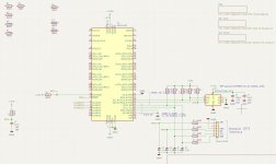
Reading a lot on the net and in the manual, I have come to the following ... see schematics.
On ADI Engineer Zone I found information that SELFBOOT needs to be pulled low when programming the EEPROM through the DSP.
https://ez.analog.com/dsp/sigmadsp/f/q-a/65986/adau1452---selfboot-i2c-eeprom
There is a WP port on the ICP3 which I hope and guess pulls the WP pin on the EEPROM low when programming. I'm thinking that this can also be used to pull SELFBOOT low at the same time?!
Anyone tried to use I2C in stead of SPI for ADAU1452??
PS. Just saw that SS_M should be pulled down via a 10k resistor, and not directly to GND. ... have corrected this
Have started looking into the programming side of things.
For my ADAU1701 builds I have been using the Wondom ICP3 programmer, which is an I2C programmer. It uses a Cypress CY7C68013A-56PVXC, think very similar to the one in USBi, so I guess the SPI lines could also be made available, but it's not routed to a connector. There are som extra holes in the pcb, which might be for exactly that, but no markings to be found.
On the other hand I also like the smaller connector used with fewer lines than USBi, but it gives a bit of headache trying to figure out how you can connect this to ADAU1452.
Reading a lot on the net and in the manual, I have come to the following ... see schematics.
On ADI Engineer Zone I found information that SELFBOOT needs to be pulled low when programming the EEPROM through the DSP.
https://ez.analog.com/dsp/sigmadsp/f/q-a/65986/adau1452---selfboot-i2c-eeprom
There is a WP port on the ICP3 which I hope and guess pulls the WP pin on the EEPROM low when programming. I'm thinking that this can also be used to pull SELFBOOT low at the same time?!
Anyone tried to use I2C in stead of SPI for ADAU1452??
PS. Just saw that SS_M should be pulled down via a 10k resistor, and not directly to GND. ... have corrected this
Attachments
Last edited:
My board is configured to use SPI for both Cypress to DSP and DSP to EEProm which is x10 the bandwidth of I2C.
For WP pin on ADAU EEProm - connect IOVDD via 10K resistor and leave it at that.
For selfboot, I have fitted a switch, IOVDD for self boot and GND for writing through to EEPROM, I reset by power cycling the whole unit at the AC mains in.
For programming the DSP I'm using this board with the firmware in this thread:
https://www.diyaudio.com/community/...-using-cypress-cy7c68013a-board.269111/page-3
So far it has been 100% reliable. there are schematics on the web for this board and I intend to incorporate it onto my new DSP board.
My SPI steings in SS are:
PCM1802 vs PCM1804, sure the former is easier being single ended, and maybe it should also be my solution. PCM1804 is though the better performer with THD+N at -104 db compared to PCM1802's -96 db or even the PCM 1808's -93db.I have used the purple PCM5102a and the black PCM1802 (with 4 electrolytics) boards available on Aliexpress, I did ditch the the ceramic caps and went films, all solder onto perf board. There are a few options and things like PDWN pin needing to be set high etc.
It's a neat decent little chip, I'll be building it into my new boards, there is a video on youtube with the chip designer disseminating a china made PCM5102a board, he is also a member on here though not sure he has checked in for a while.
If using single ended, would you not be better off using the PCM1802? It is designed for single ended whereas the PCM1804 is diff in, not sure it will like single ended inputs without a summing amp to diff converter. It looks like it maybe that the PCM1804 has the summing amp removed that is built into the PCM1802. I'm also going down a similar path right now including trying to find my way around EasyEDA, 4in/8out, ADAU1452, PCM1802, PCM5102a on a 4 layer board, running off a single 5V supply. I will be using the 2 ch. of a PCM1802 as a differential input using only passive components. PCM5102a as balanced out (not differential), just needs a resistor on the pin 3 line. Done this way, it will be happy with single ended inputs and can easily be adjusted to be an 8x8ch board. My current setup is using a Cypress board in SPI mode to program it which has been faultless-need to check the resistors used on the lines but no bother having to power up in sequence etc, just plug n play, all fitted in a rack mount case.
But after adding a diff amp in front and running single ended, maybe we arrive at the same performance .... and will we be able to hear the difference??
As for programming see abowe in post #49 .... good question .....
Was actually thinking why it is not possible to use a cheap USB to I2C converter instead of a bit large circuit around a Cypress chip?? ... Guess the programmer needs to identify itself to SigmaStudio to be known as and USBi ..... ??
Quite possible it would be of the same performance level, one expecting a SE in, and the other a Diff in.PCM1802 vs PCM1804, sure the former is easier being single ended, and maybe it should also be my solution. PCM1804 is though the better performer with THD+N at -104 db compared to PCM1802's -96 db or even the PCM 1808's -93db.
But after adding a diff amp in front and running single ended, maybe we arrive at the same performance .... and will we be able to hear the difference??
I think this is the case, SS needs to see the USBI although it can be programmed via an MCU using TCPi.As for programming see abowe in post #49 .... good question .....
Was actually thinking why it is not possible to use a cheap USB to I2C converter instead of a bit large circuit around a Cypress chip?? ... Guess the programmer needs to identify itself to SigmaStudio to be known as and USBi ..... ??
Hi SubSoniks
If you put WP to IOVDD via 10k I think it will bee seen as High, meaning Write Protected?
Or?
If you put WP to IOVDD via 10k I think it will bee seen as High, meaning Write Protected?
Or?
I'v seen the Arduino project for a programmer
https://github.com/MCUdude/SigmaDSP
But it seems only to work if you make an exported file which is then burned to the EEPROM, not like the USBi (also in I2C mode) where you directly load teh program into the DSP, and/or burn latest to EEPROM without exporting anything.
If it could have worked the way it does in USBi and be handled by eg. a ATtiny chip, it would both be cheap but more importantly save a lot of space if incorporated on the DSP board ..... but I for sure cant do the necessary programming for such a solution 😉
But that is also a SPI EEPROM, and here it seems WP is active low (the line above WP), so different from I2C EEPROMS
There have been various attempts on mcu implementation of tcpi. It is possible to make to work as USBI over WIFI except all seem to have problems that I have seen. Hopefully will get something working one day....... Atiny would be nice but esp32 on wifi would be great.I'v seen the Arduino project for a programmer
https://github.com/MCUdude/SigmaDSP
But it seems only to work if you make an exported file which is then burned to the EEPROM, not like the USBi (also in I2C mode) where you directly load teh program into the DSP, and/or burn latest to EEPROM without exporting anything.
Core board uses same EEPROM and can be configured using I2C from USBi or SPI.But that is also a SPI EEPROM, and here it seems WP is active low (the line above WP), so different from I2C EEPROMS
Note that the SS loads into DSP, not directly into the EEPROM, the DSP connects to the EEPROM. You can have SPI USBi and I2C EEPROM
Core board is configured as SPI EEPROM and can be configured as SPI or i2C USBi
Sure I seen you can mix SPI and I2C using either or on the 2 SPI/I2C busses on ADAU.
I'm sure I'll have the least problems using SPI, as I have not really seen anyone using I2C .... need to consider this.
Which Core Board are you referring to? Thanks in advance 😉
I'm sure I'll have the least problems using SPI, as I have not really seen anyone using I2C .... need to consider this.
Which Core Board are you referring to? Thanks in advance 😉
- Home
- Source & Line
- Digital Line Level
- 4 in 8 out DSP using ADAU1652