I have the 1466 version of this:
https://www.google.co.uk/search?q=a...biw=412&bih=714&dpr=2.63#imgrc=EHCOlcdOVXYN3M
https://www.google.co.uk/search?q=a...biw=412&bih=714&dpr=2.63#imgrc=EHCOlcdOVXYN3M
Member
Joined 2018
Hi Baldin-San,
FreeDSP Aurora design uses I2C for DSP access, SPI for FLASH configuration(NOPOP). You'd better have a look that.
PS.
We're passing each other, next time I hope to see you offline.
CyberPit

FreeDSP Aurora design uses I2C for DSP access, SPI for FLASH configuration(NOPOP). You'd better have a look that.
PS.
We're passing each other, next time I hope to see you offline.
CyberPit
Last edited:
Ahhh cool Thanks 🙂
Will take a real good look at that.
Yes, have just returned from my trip to Göteborg 🙂
Will take a real good look at that.
Yes, have just returned from my trip to Göteborg 🙂
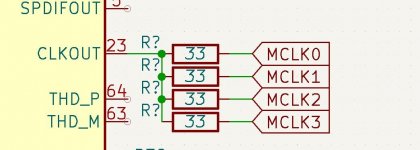
Looking at clock fanout:
As there will be 2 x ADC and 2 x DAC we'll need 4 clock lines.
ADAU1452 is able to provide 53 mA at 3.3V on all logical pins including CLKOUT.
The clock frequency will be either 12.288 or 24.576 MHz.
On the EVAL board, and on all other schematics I've seen all logic pins have been connected through 33 ohm resistors, I guess to slow the edges a bit, 33R in combination with the capacitance of track to GND plane + input capacitance of receiving chip.
Track cap will only be a few pF, and so will the input on the receiving chip .... let's say 5-10 pF total giving a RC Fc = 500 MHz - 1 GHz
https://chemandy.com/calculators/rectangular-capacitor-calculator.htm
Makes sense, and can probably reduce some ringing on the clock signal
Question is whether the ADAU1452, can drive the 4 chips directly or we need to insert a buffer?
Inserting a buffer or a number of these will introduce a short delay .... not sure this will have an effect, but the ADCs and DACs will have a clock which is something like 5-10 nS "behind" .....
PCM5102A only draws 10 uA on the inputs, at 3.3V this is an impedance of 330k, probably the same for PCM1802 .......
I would think it is safe to drive these 4 clock lines directly ..... any thoughts?
Attachments
No need for mclk on the pcm5102a as can generate it's own mclk, just need to ground the sclk pin on it.
Member
Joined 2018
4 chips load is not difficult for ADAU1452 if the board traces are not so long and limited in the same board.
The resistive load will not be a matter, but inductive and capacitive loads should be considered.
If you want to have headers for external ADC/DAC boards, I recommend adding a driving buffer and resistors near the DSP MCLK output.
CyberPit
The resistive load will not be a matter, but inductive and capacitive loads should be considered.
If you want to have headers for external ADC/DAC boards, I recommend adding a driving buffer and resistors near the DSP MCLK output.
CyberPit
Ahh yes for off board signals it would make fully sense. Not planning any extensions, so will go with the above.
By the way I have not experienced any pop sounds when programming the I2C E2Prom in my ADAU1701 designs.
If this was what you meant in #63, CyberPit?
If this was what you meant in #63, CyberPit?
Work so far.
Still really debating with myself whether to go for I2C or SPI ..... SPI seems the better way due to higher speed
Not totally sure about FSYNC on PCM1802 ... in slave mode I can't see it needs to be connected ...
Still really debating with myself whether to go for I2C or SPI ..... SPI seems the better way due to higher speed
Not totally sure about FSYNC on PCM1802 ... in slave mode I can't see it needs to be connected ...
Attachments
Member
Joined 2018
Hi Baldin-San,
It is difficult to choose I2C or SPI. So, today I went to Akihabara to buy some I2C EEPROMS (24LC256, 24LC1025)
I'll try to modify the MusicWorks1466 daughter board switch to the I2C mode. Some trials will lead me to the conclusion(Hope so...)
🤔
Regards,
CyberPit
It is difficult to choose I2C or SPI. So, today I went to Akihabara to buy some I2C EEPROMS (24LC256, 24LC1025)
I'll try to modify the MusicWorks1466 daughter board switch to the I2C mode. Some trials will lead me to the conclusion(Hope so...)
🤔
You need to connect FSYNC to HIGH. It works as a gate switch of BCLK.Not totally sure about FSYNC on PCM1802 ... in slave mode I can't see it needs to be connected ...
Regards,
CyberPit
FSYNC high in slave mode.Not totally sure about FSYNC on PCM1802 ... in slave mode I can't see it needs to be connected ..
Have been working on the schematic and defining all the components in KiCad.
Really happy I did the jump to KiCad. It has all the features I need, and is relatively easy to use, and not so different from other tools. I'm getting the hang of it I think 🙂
Have not found any good alternatives to STD2805 for the low voltage drive (LDO) on JLCPCB ... any suggestions? Need to have high Hfe. .... can of course be had on Mouser
Settled on SIP for both programming interface and EEPROM.
Slowly starting the PCB layout ... placing components for plate amp use ...
Happy to hear any comments on schematics, and especially if I have made any mistakes ... thanks in advance 🙂
Attachments
Member
Joined 2018
Hello Baldin-San,
CyberPit
In my case, I will choose MJD45H11xxx for FreeDSP OCTAVIA. It has HFE equal or more than 100 under the 1A range and JLPCB stocks.Have not found any good alternatives to STD2805 for the low voltage drive (LDO) on JLCPCB ... any suggestions? Need to have high Hfe. .... can of course be had on Mouser
CyberPit
Cool stuff .... I'll go for that
Have been thinking and reading a bit more about decoupling caps.
Plan was to use 10uF X5R 0603 || 100uF X7R 0603
The pcb will be 4 layer, and I'll dedicate the 2 inner layers to Vcc and GND. Unfortunately the inner layers are divided by a 1 mm thick core for the 1.6 mm pcb, and therefore not close enough to act as a large cap. If you pay you can of course have it 😉 ..... So placement of the caps becomes important.
So consider using 10uF X5R 0603 || 100uF X7R 0402 .... and hoping I will not have to do any hand soldering of the 0402s 😉 ....... on the other hand, when using the assembly service, there is no good reason not to go for the smaller casing reducing the induction in track length, and the parasitic inductance of the component itself
.... I'll go for thatHave been thinking and reading a bit more about decoupling caps.
Plan was to use 10uF X5R 0603 || 100uF X7R 0603
The pcb will be 4 layer, and I'll dedicate the 2 inner layers to Vcc and GND. Unfortunately the inner layers are divided by a 1 mm thick core for the 1.6 mm pcb, and therefore not close enough to act as a large cap. If you pay you can of course have it 😉 ..... So placement of the caps becomes important.
So consider using 10uF X5R 0603 || 100uF X7R 0402 .... and hoping I will not have to do any hand soldering of the 0402s 😉 ....... on the other hand, when using the assembly service, there is no good reason not to go for the smaller casing reducing the induction in track length, and the parasitic inductance of the component itself
PCM5102, are your 1K resistors final values? guessing not but just checking. Also it looks better to not use mclk to PCM5102a and let it generate it's own clock, would mean you would only need split to 2 mclk lines instead of 4.
ADAU master clock at 24MHz instead of 12MHz? Working with a lower clock is more forgiving unless you need a higher clock for feeding something other than the DSP and ADC's?
ADAU master clock at 24MHz instead of 12MHz? Working with a lower clock is more forgiving unless you need a higher clock for feeding something other than the DSP and ADC's?
Hi SubSoniks
The 3 x 1k resistors + 2.2nF is there to firstly provide a low pass filter on ca 72kHz and reduce output to 1/3.
A consumer power amp should/would have an input sensivity of 1 Vp (0,775 V RMS) for full output swing
The PCM5102A can deliver Vp=3V
So to level match we should divide by 3.
This to run the DAC as close to FS for linearity right up to clipping of the amp.
Some amps might have a lower sensivity, then it's just a matter of the second resistor.
Will it matter for the sound .... not sure, as we are only talking about one bit less or more
As for MCLK for the DAC. You are probably right. Guess you can just leave the pin not connected.
I guess it could be up for measurement on noise and THD to see what is best. It can be omitted by dismounting the 33 ohm resistor leading from the DSP.
I can see in the data sheet it is recommended to use the internal PLL to lower the EMI radiation from the line.
Have you tried to do both to see the difference in performance?
Yes 24 MHz to allow for different higher clocks. If I need it sure I doubt 😉
I've not tried feeding the 5102 an MCLK, mainly because I think I could mess it up. Re the 3 x 1K's, think I would use the recommended 470 Ohm and double the cap if available. Re the divider, possibly a bit low resistance, may end up loading the the 5102 output too much and end up increasing distortion, raising the resistance will raise the noise floor due to 'Johnson noise', a lot of old CD players were 2V @0dBfs IIRC.
Also IIRC SCLK pin would need to be tied low if not feeding an MCLK signal.
Re crystal, I think all the chips will run at 96KHz with a 12meg?
Also IIRC SCLK pin would need to be tied low if not feeding an MCLK signal.
Re crystal, I think all the chips will run at 96KHz with a 12meg?
You could be very right about the loading. Will check that .... must admit I hadn't really thought about it 😉 ..... not sure why not .... hmmmm Thanks ....
Well for a CD player, it was not really a problem as they would normally look into an input pot, acting as the attenuator, or a buffer running on +-15V or there about.
About Johnson noise or thermal noise, 10k at 20 deg C is 1.8 uV rms .... vompared to 0.775 Vrms which is about -114 db, if I get it right .... so will not be the limiting factor here
My current ADAU1701 + PCM5102A is running on MCLK .... have not really considered whether it is a problem .... could maybe try it out there.
I think you need 24MHz for running 96kHz on the PCM1802 ADC as it only supports from 256 Fs up to 768 Fs
Last edited:
- Home
- Source & Line
- Digital Line Level
- 4 in 8 out DSP using ADAU1652