Ampohm PF XTI AL PIO caps

I have for sale 4 pieces 0,47uf verry little used top pio caps from Ampohm.They are in like new condition.Leads are about 40mm long.This caps are truly top notch in sound,verry transparent,musical and never harsh.The sound is so smooth and just musical.Plese look online for positive tests.They are way betther than many other modern PP and Pio caps.For verry little price you have a chance to have truly verry good sound.Price is 60 euro for all 4 plus shipping.

IMG_20230327_110334.jpg

Clicking on both channels

A few months back. I bought an XDUOO MU-604 DAC. I installed the drivers from the Audiophonics web site and all was good. At least for a while!

I then noticed that both channels started clicking when playing music or watching movies. This only happened on USB, however the optical and coax inputs were fine. I tried both usb inputs and several different usb ports on the pc, but still no good. I thought the usb board may have gone faulty so I contacted audiophonics for a return.

Sadly there was no fault found, but they sent a replacement anyway in case it was an intermittent fault. When I got it back, more clicking!

I uninstalled and reinstalled the drivers to no good effect. I had already checked all my cables etc. and was a bit perplexed.

I therefore uninstalled the xduoo drivers and deleted all the files and then reconnected and allowed it to install the native Windows 10 drivers. Problem solved!

It looks like at some point some new windows components have caused some slight incompatibility with the xduoo drivers. I installed asio4all so I could use asio playback as this was part of the xduoo driver functionality.

I thought I’d mention this in case any of the projects here use the same chipset drivers as the xduoo and may experience similar issues or if anyone with an xduoo DAC has a similar problem.

NAIM Audio NAP 110 restoration

Good morning.
A few months ago I took possession of a Naim nap 110 which has undergone maintenance over the years.
The photo shows its interior with tabs.
One channel has original transistors, while the other has 2N-3055s which are similar to the MJ15003s (RECOMMENDED) but not the same. I would like to replace them with two MJ15003s to start with.
The capacitors that were originally all tantalum are now electrolytic in many parts. I would like to put them back in their place.
How about?
Do you know the exact values of tantalum capacitors?
Other advice will be appreciated.

I would like to clarify that currently the final also plays discreetly and on for hours.
Only the idea of bringing it back to a more original standard
makes me calmer.
Greetings

Attachments

  • IMG20220213122324.jpg
    IMG20220213122324.jpg
    519.6 KB · Views: 1,500

Top end of Mark Audio 7MS?

I have the 5.3MS drivers, and have been quite impressed. However, in a small sealed box they (of course) can only go so low with conviction.

I'm now considering a lowish extension down to around 200hz crossover (in a WAW). The 5.3 can do this but I'd like more impact/SPL than a little cone is ideal for. So the 7ms is quite an appealing step up. My question is how much does that sacrifice the top end?

For perspective, I also have the 11MS and they are surprisingly good at the top end for their size... until compared to the 5.3 or a decent tweeter. So I/m wondering if a middle ground like the 7ms may be nearly as good up top? If not, then a tweeter-assisted wide-range might be an preferable - crossed above our ability to discern very much about location etc..

Thanks,
Kev

Sound Code Systems SCS Mosfet Power Amps

Sound Code Systems. the LA Glam Slam amp of choice. these old Mosfet PA power amps were awesome in their day. they use the famous and well loved Hitachi Mosfets. I think the same used in Haflers?? I have had this sitting around my shop for a dozen years or so and just never got around to doing anything with them. I they both worked years ago when i last tested them. the larger 2600A i used about 3 years ago for a bit. but both should be gone through and cleaned up etc.

the 2600 $150
the 2350A $100

plus shipping and they weigh a LOT!

Attachments

  • 20211220_143017.jpg
    20211220_143017.jpg
    617.3 KB · Views: 372
  • 20211220_143038.jpg
    20211220_143038.jpg
    689.2 KB · Views: 321
  • 20211220_143046.jpg
    20211220_143046.jpg
    615.2 KB · Views: 326
  • 20211220_143217.jpg
    20211220_143217.jpg
    659.7 KB · Views: 308
  • 20211220_143222.jpg
    20211220_143222.jpg
    727.6 KB · Views: 358
  • 20211220_143236.jpg
    20211220_143236.jpg
    690.2 KB · Views: 346

What sound deadening material for inside my LCR box’s (not stuffing)? Box resonance.

I have some 2-way 12” with a cd / horn LCR speakers that I DIY’d that I believe have a terrible resonance due to the dimensions of the box and the 3/4” MDF board (bracing too).

I would like to put some kind of dynamat adhesive mat and some egg crate foam type stuff behind the drivers AND still put some stuffing back in, what do you guys recommend for doing this?

For Sale Abacus Aikido Tube Preamp - Low Voltage 6GM8 Version

Hello all!

Abacus Audio Aikido Tube Preamp. This is the 6GM8 version, not the 12AU7 version. The preamp has the John Broskie Aikido tube preamp PCB - the LV Aikido circuit (low voltage). The 6GM8 (6N27 / ECC86) tube is perfect for this low voltage application - 24 volts B+.

You could drop in another tube like the 6922 or 6DJ8 (do not put in a 12AU7, you will destroy one of the two triodes), but those tubes are best run with higher B+ Voltages...the best tube is the 6GM8 (per Broskie)....and unfortunately they are not cheap.

Comes with extra 6GM8, and programmed remote that does volume, input, power, standby and mute.

Audition possible for those in Chicago area. How's $525 for a ready to go Aikido?

Attachments

  • PXL_20230126_172849352.jpg
    PXL_20230126_172849352.jpg
    290 KB · Views: 436
  • PXL_20230126_172938163.jpg
    PXL_20230126_172938163.jpg
    351.6 KB · Views: 434
  • Aikido LV.pdf
    Aikido LV.pdf
    1.4 MB · Views: 204
  • Like
Reactions: sportster

Cheaper substitute for Lundahl LL1671

I wanted to get a taste of Andrea Chiuffolis Amplifier End but the Interstage Transformer is a bit on the pricey site for a mear test.
He uses the LL1671 in Alt Q configuration parallelling the four primaries and putting the secondaries in series.
Lundahl ommits so much relevant data that I as a novice can not find a substitute.
In my application I use the amp only above 100hz which should make it easier to find a cheaper substitute I think.
Any help is greatly appreciated.

Klaus

Help With Compression Driver/Horn Selection

I have been listening to Dynaudio C1's crossed at 250Hz with my low end coming from DIY Woofers with ScanSpeak, 32W/4878T01 Drivers. Sound is clean, detailed and quite amazing..............

However, I am longing for that Live, Horn Dynamic Sound that I am missing in my current setup.

I was thinking of just buying Klipsch Forte or Heresy IV's and get this out of my system, (or stay happy with them), however, what about DIY?

I can use my existing Woofers for the low end and just build the cabinets for the mid and tweeter drivers/horns........

I have been searching a proven receipe and just get more and more confused.

I am thinking to use active X-Overs and discrete amps.

Can a driver/horn guru on here make recommendations for me with respect to what drivers and horns to buy and build?

Thanks for supporting this ride............

Need tips for building a 2 foot high box to raise my speakers

So I built a pair of Crites CornScala speakers (Klipsch Cornwall knockoff), and they sound great but I use them in my basement when I work out, and I'm 90% of the time standing up.

I've noticed the woofers sound anemic when I'm standing up, but are fine if I sit on the ground. I figure I would need to raise the speakers at least two feet off the ground. Chains above arent an option.

My question, what is the best way to go about this? I was thinking using plywood and cutting 4 big square holes into each side? I'm afraid If I make a closed box, it would resonate. Am I overthinking this?

Any tips welcome, thanks!

For Sale to US: QTY 2 Raspberry Pi 4 model B 2GB

SOLD!

These were pulled from a working active loudspeaker project. Quantity 2 available of the 2BG version. Excellent condition. Without power supply or SIM card.

$100 for the pair, including shipping. Would prefer to sell together, but will also consider selling individually for $60 each shipping included.

NOTE: If you need a SIM card I can offer a new in packaging Samsung EVO plus 32GB class 10 for $10 each or $15 for two. Compare to:
https://www.amazon.com/Samsung-MicroSD-Memory-Adapter-MB-MC32GA/dp/B07F24ZBPV/ref=sr_1_5

Attachments

  • IMG_20230907_171730566.jpg
    IMG_20230907_171730566.jpg
    474.7 KB · Views: 57

Design an amplifier with wide voltage range ;)

Hello diyaudio friends, I hope you are very well, I would like to ask a question, I am looking for a Transistorized amplifier that is capable of working in a wide range of voltages, let's say from 25 +/- VDC to 80 +/- VDC, I know that there are parameters that are very difficult to adjust automatically for that wide voltage range, such as bias, etc. but they can be adjusted manually, I'm a bit of a novice in audio amplifier design, but I've been working on an amplifier that can meet the needs I'm looking for, I just don't have anything concrete yet, and I would like some help, guidance or advice from the most experienced, if you could help me with some information I would greatly appreciate it 😀

25W Class A amp with Lateral MOSFETs

This time I wanted an amp that will combine qualities of my F5 (made with k2013/j313) with a certain seductive gentlenes that comes with good tube amps (member p18 recently made a nice amp with 6C33C that inspired me). Comparatively, I wanted something like F3 but with more control, more gain, more power and insensitiveness to characteristics of source and speakers.
I worked for a few months on it and tried a number of ideas (best candidates were a circlotron with LU1014 and a single rail version of F5 with BJTs at input and Laterals at output) but the buck stopped here:
An externally hosted image should be here but it was not working when we last tested it.

I chose single rail PS becouse it enables using the benign reactive component at the output that makes "sound tailoring" possible.
Transformer is 500VA (2 x 40V AC, one secandary per channel). Cap. multiplier provides smooth and fast source of power (1.5mV ripple at 1.3A). 10mf ELKOs are Siemens Sikorel, bypass are MKC in PS and MKP in direct signal path.
Q1 provides high Zin and Low Z feedback point. Q2 gives all the voltage gain (OLG is about 50dB), it runs on about 7.5mA and that's more than enough to drive a pair of Laterals in push-pull Source follower topology (there are jumpers over Source resistors which are taken off when setting the bias with P2 ; P1 sets the half of the PS voltage at the output).
Here is the 90kHz square wave at the output loaded with Epos 5M (two way, bass reflex, 4 Ohm speaker). CRO was set at 5V/div vertical and 2uSec/div horizontal:
An externally hosted image should be here but it was not working when we last tested it.
Construction looks like this:
An externally hosted image should be here but it was not working when we last tested it.
and the rest of the pictures are here:
Projekat: SVAJA - diayudio.rs

Schematic :
636182d1505823180-25w-class-amp-lateral-mosfets-svaja-aspublished-gif


Version 2.0 - post #180


.

Datsv3 vs Umic1

Long story short. I have a DatsV3 gifted to me by one of my automotive students.
Im now in need of a calibrated mic.
Is there any guides as to how I can buy a cheap mic and create my own calibration file. What if I buy just a Mic pickup and then what kind of circuit would I need to build around it.
Next question it would seem that the Dats unit has a sound card. Has both an amplifier and a mic. i.e. both input and output. Capabilities.
In fact I have setup True RTA and am able to use use my Dats audio input (It shows up as a USB Audio Codec).
Also read the article on how to use the dats with REW on a mac. Plan to see if I can use the same steps on windows.

Has anybody done this on windows ?.
Whats the most economical way to build a mic that I can use with REW or TrueRTA. Or any of the other spectrum analyser apps.
Im in the process of trying to see how accurate these spectrum analysers are on my phone when I get my hands on a friends Radio Shack DB meter. Most have a peak hold function. And some even allow you to save the results to a txt file. On the phone.
Some of the android apps I have tried are
Spectrum Analyser Pro / Spectroid / SpectralPro / RTAPro /
Im trying to see if I can sort out my tool box without having to invest in a 100-200$ Mic.
Not sure why but info on Dats seems to be very sparse.

For Sale Pass F5 Amplifier for sale - Brisbane Australia

Hi Everyone,

I have a diy Pass F5 amplifier for sale. Located Brisbane, Australia

Built using matched linear audio systems transistors purchased from the DIY audio store
Hifi2000 4u case
Speaker protection
Softstart
Ground lift circuit

Asking price $800 plus shipping.

Works and sounds great. Reasons for selling, I have no idea what to do with so many amplifiers. I have 3 x diy amps now honestly running out of space in my apartment.
PXL_20230908_043455274.jpg
PXL_20230908_043600157.jpg
PXL_20230908_043609003.jpg
  • Like
Reactions: Bryguy and arteom

DIY amp with Primare a33.2 casing and transformers

Peeps. I had a dead amp board of Primare A33.2 which I failed to troubleshoot and fix. So I would like to use the parts to build a Class A or Class AB amp. It’s a dual monorail so have two transformers. The secondary windings are 44.6v 56v 0 44.6v 56v. I don’t have any VA rating written on it. It’s a 125w amp and I see 10000uf 63v caps of 8 in total. Am thinking to reuse the transformers, power caps, heat sinks and casing. What would you suggest to do. Honeybadger, Pass F6 or another ? I already saw for naim nap 250 clone this is way over and won’t work. Pic of tranny attached
IMG_9770.jpeg

Trying to work out the function of tubes for purposes of tube rolling

A tube kit amp I'm working on specifies that the output tubes are a gain tube and a follower to reduce output impedance, and lists the best tube types for each stage. In most commercial amps I see, they use the same tube in all locations, presumably for simplicity? Is the gain tube/follower tube common in most small-signal output stages? Should that affect how I think about tube rolling (ie, expensive NOS tubes in the gain, cheaper tubes for the follower)?

I have two real world examples to share, where I am trying to understand the tube rolls. The first is the Audio Research DAC3, which uses four 6922 tubes in it's output stage (schematic here: https://arcdb.ws/Database/DAC3/ARC_DAC3MKII_schematic_and_parts_list.pdf). I assume V1/V2 are the gain tubes and V3/V4 are the followers, so changing V1/V2 would have the biggest impact on sound?

My second example is the Audio Research SP8 preamp (https://www.arcdb.ws/Database/SP8/ARC_SP8_manual.pdf). It uses three tubes in the line stage and three tubes in the phono stage, as well as two more in the power supply. Notably, they output sections use two 12AX7s plus a single 6922. I don't understand this circuit, and don't really have any assumptions about which tube does what.

Anyway, just trying to get a bit more understanding before I stock up on vintage lightbulbs.

CSS-Detroit DIY 2023 speaker event Sept 15/16....

https://diy.midwestaudio.club/discu...gether-minus-meniscus-and-moved-to-detroit/p1

This is a speaker DIY event. I know it's very close, but figured maybe some semi local people might want to come.

I'll have my Monoculus and Bottleships present for demo. I'm not the organizer, just an excited participant that is helping with providing of some gear.

B&C DE500 Pair 8 ohm

I have a pair of used B&C DE500 8 Ohm compression drivers. These were used in a two way home system. They're a little beat up from laying around my garage for a few years. Both voice coils test good. I'd like to get $70 for the pair plus $30 for USPS Flat Rate shipping to US.

Attachments

  • DE500-6.jpg
    DE500-6.jpg
    539.1 KB · Views: 91
  • DE500-1.jpg
    DE500-1.jpg
    348.7 KB · Views: 79
  • DE500-2.jpg
    DE500-2.jpg
    418.4 KB · Views: 105
  • DE500-4.jpg
    DE500-4.jpg
    307 KB · Views: 97
  • DE500-5.jpg
    DE500-5.jpg
    285.9 KB · Views: 94

802 Diy speakers

Hey guys, usually I post amps in here on this forum however, I thought you will like also some unique speakers 😉

I am building speakers similar to B&W 800D, but its not copy nor clone. Its build from scratch by me using non bw speakers. Ofc I saw youtube videos of build process as well as diy copies. I am not doing that, I go my way but I like the design and some features so I am going to use it as a template.

This is going to be build thread of some sort, even though I am in the middle of process, but anyways... I was posting processes I did so far on the local cz forum, but I think this deserves wider presentation 🙂

Begining...

To make this all possible I started with mid speaker as they call it "turbine head". I told to myself that if I am not going to have this midrange speaker enclosure, its pointles to do anything or start by other parts... so I started to draw in Blender, a lot. It looks simple, but modeling really nice teardrop isnt as simple as it looks on first sight. Original b&w is very prolonged and I didn't wanted my speakers to be as big and deep. So I shortened it and modeled for standard speaker size. The result is 42cm deep teardrop with nearly 30cm diameter. First concept below:

3-Dkomplet.png

I have a friend who is master of 3d printing so he did print these for me out of PLA. Wall is about 7mm thick with trippled outside walls. I didnt wanted exotic materials, because of several reasons: price, and mainly print realiability. This was printed for nearly 2 days a piece. To make very shallow angles printable its impossible to make it as a one print so my teardrops are glued from two parts by epoxy. To make precise fit I printed also small guides and also speaker mount is sandwitched thanks to that. Below a few pictures of wall "cut" from one damaged print and front piece + tear piece prepared for glue:

IMG-6047.jpgIMG-6026.jpgIMG-6028.jpg

more glue:

IMG-6024.jpg

glued it already looked amazing, it had very nice "pearl" shine thanks to print layers, however because of front piece it looked not as good so I had to do something about it. I watched milion videos how to smooth 3d prints but tried my own way as the main point was somehow same. So I sanded all surface by 80grit, then I filled all surface by 2part polyester filler specifically for plastics. A lot of sanding and dirt... i looked like narco baron 🤣

IMG-6044.jpgIMG-6042.jpg70688277249-85511515-5-BC4-4-D8-E-B1-A8-688438297-E98.jpg

the result was really smooth, but not enough so one more layer and after sanding:

IMG-2265.jpg

all 3d print raster dissapeared and I was prepared for primer. First coat was like indicator where the bad spots still are so again sanding and more primer coats. After about 4th or 5th coat of primer and water sanding it was absolutely smooth. I was very happy with the result so I knew the main part is acomplished so I started ordering wood and remaining parts. (I'll get back to teardrop later no worries)

Main body

After I modeled whole speaker body in blender I started to export particular parts into autocad to prepare shapes to be cnc cut from mdf. I wanted all internal matrix parts to be cnced because of consistency which would be impossible to be done by hand. Honestly, it was extremely difficult to find company for this small task, I was searching for a month and some not even responded to my emails, some after second mail stopped communication 🙁 terrible. After long search I found some young guys doing something compeltely different than wood but they had cnc and helped me, maybe a luck but finaly I got my parts:

IMG-6081.jpg

only the matrix parts are CNCed, I did front baffle by myself with mill as well as some other pieces to safe time and money. One particular tricky piece was doing big radiuses on top and bottom edge of the front baffle. So I did some calculations and milled steps to get the rough radius, looked like this:

IMG-6062.jpgIMG-6063.jpgIMG-6066.jpg

so i could smooth out and respect the radius I have made radius sanding tool out of cut piece of PVC pipe:


the result using this custom tool:


bottom radius is smaller ~30mm as there is wall continuing by 10° angle and top bigger radius is ~40mm to smoothly continue on 25° top wall.

After I had all the pieces I needed to figure out what to use for curved walls. I've found out, there is a thing called flexible ceiba plywood so i have order a few sheets 8mm thick and let them cut to size. I was a bit worried by how flexible it is but oh my... it is wobbly and bendy!


some matrix putting together:

IMG-6277.jpgIMG-6269.jpgIMG-6266.jpg

To make box "standing" at least on a piece of flat part I did small ending at the back flat where the screw holder will go:

IMG-6271.jpgIMG-6272.jpg

more sanding and connecting radiuses:

IMG-6274.jpgIMG-6273.jpg

change pre-amp/amp freqencies for buttkicker LFE minis

Hi,

Note: also posted in head-fi but no response.

I wasn't sure about which section to post this in here, so apologies if I've got it wrong.

I have two Buttkicker LFE minis screwed into the frame of my sofa. The sofa is on rubber mats.
The Yamaha RX-V477 LFE output goes into a Y-splitter, one leg going to a Dali E12F sub, the other into another Y splitter connected to the RCA inputs of a Fosi P1 preamp. I've replaced the tubes with 5654W tubes.
The RCA outputs go into an Aiyima A07 amp, with which I'm using a 32A 5V power supply. I have a 48V supply but don't use it because the fan is noisy and it doesn't seem to make much difference.
The speaker outputs of the A07 are connected to about 7m of 2.5mm2 copper speaker cable.

The buttkickers rattle a bit at lower frequencies, a problem that wasn't solved with the rubber feet on the sofa. I have the crossover on the AV receiver set to 120Hz so that the Dali sub can handle lower frequencies, but this also means that I get eg male voices through the buttkickers, which I do not want. Obviously I can buy a crossover and connect the LFE output to it and only send higher low frequencies to the sub and lower low frequencies to the buttkickers, but I'd like to try and do something with the pre-amp and amp, and in any case I still want the main sub to handle the lower low frequencies.

The buttkickers are sensitive down to 10Hz, but the pre-amp and amp only pass a minimum of 20Hz. The pre-amp has bass and treble tone controls, and obviously I have bass on max and treble on mimimum.

I would like to modify pre-amp and amp to pass signals down to 10Hz and nothing above something like 100Hz, and also modify the pre-amp tone controls to amplify a much lower frequency range so the bass knob controls something like 10-40Hz and the treble 40-80Hz. My (somewhat limited) understanding of electronics leads me to believe that I can replace a few capacitors to achieve some - if not all - of my aims.

I'd be grateful for any thoughts, even "you should have read the FAQ, it's all there", "why on earth are you using a valve pre-amp for low frequency transducers?" or "no, not possible, too complicated to juggle caps and resistors". I'm capable of using a soldering iron.

Pics are from the pre-amp (which has tubes, hence the hesitation about which section to post this in).

Thanks!

Attachments

  • MicrosoftTeams-image (3).jpg
    MicrosoftTeams-image (3).jpg
    340.9 KB · Views: 59
  • MicrosoftTeams-image (2).jpg
    MicrosoftTeams-image (2).jpg
    475.5 KB · Views: 57
  • MicrosoftTeams-image (1).jpg
    MicrosoftTeams-image (1).jpg
    357.6 KB · Views: 61

junkbox transformers - options for Tubelab PCBs

I've been directed here by a kind member in the tube sub-forum of DIYAUDIO.

I've pulled two output transformers and a power transformer out of storage.

There's clearly a bit of cleaning up to do on the output trannies!

IMG20230830104729.jpg


IMG20230830104741.jpg


IMG20230830104758.jpg


Can anyone recommend a suitable TUBELAB amplifier to build using these pieces of iron?

Output transformer specs:

5K to 8 ohms
Frequency Response 20 Hz to 90 kHz
Maximum DC Bias Current: 90 mA
Primary DC Resistance: 370 ohm
Primary Inductance: 40 H
Part Number Transcendar TT-012-OT

Power transformer specs:

16933603125352515786251855786051.jpg

Yamaha RXV2700 with sub

Hello, I've got a yamaha rxv2700 amplifier, which apparently has 140w on each of its 7 channels, I think.
I have a Lanzar max pro 8" 4ohm subwoofer, with around 800w peak and 400w rms.
I'm pretty amateur, how could I run the woofer of the amplifier? I assume I have to bridge some channels to reach the 400w, but I'm not really sure.
I have a crossover for the subwoofer already, just need some help wiring it, thanks!
Back of yamaha rxv2700:
image.jpeg

Note: I know that it's supposed to be used as a home theatre amplifier, but I don't have anything else around at the moment, would be cool to get it working.

  • Locked
Bliesma T34B rubbing VC - impedance curves

So my T34B saga continues. Now that my back chambers are re-attached, there is a new issue.

Today, listening to the tweeters with a 1V sine wave sweep, I can hear some fuzz around the area under 1.5k on one of the driver's.

It sounds like a rubbing VC, so I ran quick impedance sweeps on the DATS test setup. Low and behold, it looks like a rubbing VC. The TSPs are also a bit different which shouldn't be on a matched pair of drivers, unless they're only matched for FR and not overall parameters.

My question is, has anyone with these tweeters measured them as a pair and how did they look?

Attachments

  • 20230901_192014.jpg
    20230901_192014.jpg
    203.9 KB · Views: 175
  • 20230901_191826.jpg
    20230901_191826.jpg
    195.1 KB · Views: 179

For Sale to US: QTY 18 - LM3886 "XY brand" populated chip amp boards

SOLD!

Here is another lot of great DIY parts: LM3886 chip amp boards.

There are I believe 17 or 18 of them. NOS condition. These are great for making small amps and having some DIY fun!

Boards are as shown. Also includes a bunch of mica or insulator pads for heatsink mounting and some hardware for same.

Prefer to sell as a lot.

Please PM me if interested.

Attachments

  • IMG_20230907_113203793.jpg
    IMG_20230907_113203793.jpg
    474.7 KB · Views: 71

Aiyima TUBE-A3

Hi,

AiyimaA3.jpg


I bought this pre-amp and connected it to 12V 4A DC power-brick I already had. I changed the 4 grep film caps to Clarity Cap CSA 4.7uF 250V capacitors, changed the two JRC 55320 op-amps to JRC Muses02 and the valves to two matched Mullard M8100 NOS valves. I'm waiting for the two CSA 10uF 250V caps to change the two 10uF electrolytic capacitors between the two op-amps. I measured the potential difference between the anode & cathode on the valves and it's 70V. The valves are specced at 120V. How could I change the potential difference between the anode & cathode to get closer to 120V without changing the heater voltage?

I did notice the polarity was reversed so I just plugged the output red lead from the preamp to the white terminal on the Arcam rHead headphone etc...


Thanks
Haider

Dynamikks DB-8.2 Speakers

For sale truly top sounding speakers from Germany.Coaxial drivers with Horn-TL enclosure.The speakers are in verry good condition.You can drive this with tube amps or tranzistor amps.This speakers have top timing and big sound scene.The new price was by 7000 euro.The price is 1100 eur😵nly pick up,maybe for someone from Austria,Germany or Countrys near Slovenia.

Attachments

  • 20230625_172451.jpg
    20230625_172451.jpg
    344.1 KB · Views: 143
  • 20230625_172444.jpg
    20230625_172444.jpg
    329.7 KB · Views: 131
  • 20230625_172457.jpg
    20230625_172457.jpg
    401.5 KB · Views: 154

For Sale to US: Box-o-Integrated Circuits ...from my inventory to yours!

SOLD!

I'm trying to clear out some parts and downsize in preparation for a move. I have on offer one "box 'o ICs". This contains lots of op-amp and signal processing circuits, some class-AB chip amps, plus a component tester, dip sockets, etc. It's all in a large shoe-box that I will repack for shipping. There is an approximate inventory below but I did not count up parts so I cannot guarantee quantities, etc.

I would like to just ship all of this to a single buyer, US only.

Asking $60 with shipping included. Please PM me if interested.


QTYDescription
30MC78M12CT 12V fixed voltage regulator
20NE556N dual timer IC
100LM555CN timer IC
3LME49740 quad audio op-amp IC
10LME49720 dual audio op-amp IC
17LF353 dual op amp IC
100NE5532 (Texas Instruments) dual op amp IC
5MC33274 quad op amp IC
20TL074BC quad op amp
100LM358 dual op amp
10LM317L adjustable positive voltage regulator, TO-92 case
14LM317 adjustable positive voltage regulator, TO-220
14LM337 adjustable negative voltage regulator, TO-220 case
252N4401 600mA 60V NPN transistor
2INA134 differential line receiver
2OPA2132 dual op-amp
2LTC1062 5th order low-pass switched capacitor filter
24TDA7293
10SSM2018T VCA
4SSM2164 quad VCA
32NE5532 op amps (Fairchild)
56UAF42 second order active crossover IC
4LM7805 5V regulator
4MCP130-475DI/TO supervisory circuit - reset at power on
44017 decade counter (HCF4017)
44093 quad Schmitt trigger (CD4093)
44510 BCD up/down counter
4SN74HCT251N 8-1 multiplexer (HCU)
74HC251 8-1 multiplexer (HC)
474HCT04 hex inverter
1274HCU04 hex inverter w/unbuffered outputs. “the XX74HCUXXXXX, consists of single-stage unbuffered CMOS compatible devices for application in RC or crystal controlled oscillators and other types of feedback circuits which operate in the linear mode”
10LT1054 switched capacitor DC voltage doubler/inverter
25MC33201 rail-to-rail single supply op-amp (single amp, DIP-8)
25OP-07D low-offset low-noise single op-amp
2OP-275GPZ JFET dual audio op-amp
2OP-482 quad op-amp
3SI8602AC-B-IS I2C isolator

Pumpkin preamp - ordered by Steen , official making thread

well ...... seems ages ago ,buried in some obscure DiyA Pass thread , after few quickie (on back of napkin) modifications of XYWZwhatever BOSOZ , my budy Lucky Luke (AKA steen) , demanded one little preamp with balls ....

few posts later , LL have some ideas about topology, perfectly good for me , just because I'm good at paper (napkin) and hand calc almost as he is good in making amps ........

little later - I already have some quickie quickie drawn , but somewhat flipped in regard to LL's idea,with added output stage(s) etc.

main reason why I flipped it is because I feel ( well - I rarely think,anyway) that's smart to use some non-audio-fancy-schmanzy Jfet , which is easy to find in near tobacco store, with all other parts .....

well - result is here (lookie lookie schmtc)

crazy process of :Pumpkin: delivery is also crazy documented in THIS
thread .........

I can just say tnx to entire OFF TOPIC MOB , just because they make my life miserable with regular questions "will it drive F4 " etc . :devilr:

anyway ......... for first post is 'nuff


schematic:
(next post -The Shunty)...........

EDIT BY MODERATORS:

With Choky's permission, I have created a new thread the is the same as this thread but with almost all Off Topic posts removed for easy reading by those making the project.

http://www.diyaudio.com/forums/showthread.php?s=&threadid=119070

The new thread is closed and possibly won't be updated, so members should keep checking back here for latest info and amusement

Variac

END EDIT

Is there a simple one-to-one simulation for Blameless amplifier in LTspice?

Hi all,

I keep running into people mentioning Blameless amplifier all the time.
Searching on the internet I could only find schematics from Douglas Self articles.

Is this it? and is there a simple LTSpice simulation that tests all of the parameters?

It was not hard to put one together myself, but I only know so much in LTspice so maybe there can be more suggestions on what to measure?
Maybe this can be a good exercise to learn more about LTspice...

Thanks

Attachments

  • blms.gif
    blms.gif
    25.1 KB · Views: 463

Neutrik A1 analyzer repair project

Hi all


I have a Neutrik A1 audio analyzer up on ebay. The PSU is dead (torroidal trafo need to be replaced) but apart from that it is in very nice condition. It could be a nice repair project for the long winter evenings. Sadly I don't have the time for it, so I'm letting it go.


s-l1600.jpg


It comes with a full service and calibration manual as a pdf.


Neutrik A1 Audio Test & Service System | eBay


(I hope it is ok posting it here?)

Mirrand Audio Tssa1.8

Two mono blocks with separate regulated Psu.Top sound,in my system better than F5 or F6 that I also build.The bias is set on 1.6A so you become about 30watt in class A.Verry goid parts and top Thel regulated boards ,this psu is better than any standard psu.Verry good caps like Nichicon FG and Kemet big screw on caps.I think to get about 1200 eu for this set,or best offer.The shipping will be high becose the psu weight about 15kg and bouth monos about 12 kg.
For more questions just contact me.

Attachments

  • 20230902_124619.jpg
    20230902_124619.jpg
    580.3 KB · Views: 109
  • 20230902_124637.jpg
    20230902_124637.jpg
    462.3 KB · Views: 119
  • 20230902_124642.jpg
    20230902_124642.jpg
    611.6 KB · Views: 113
  • 20230902_124730.jpg
    20230902_124730.jpg
    711.3 KB · Views: 112
  • 20230902_124734.jpg
    20230902_124734.jpg
    585.2 KB · Views: 109
  • Like
Reactions: vassilis1984

Building Passive Crossover for Eminence Beta 12A and APT50 Tweeter

Hello,

I am trying to build a passive crossover for the first time and here is the rough drawing of crossover that I sketched earlier today.

The drivers that I am trying to make use with the crossover are;

Eminence APT50 super tweeter
https://thespeakerfactory.com.au/products/eminence-apt50-horn-driver-1-50-watt
=> Recommended Crossover 3.5 kHz / 12 dB kHz

Eminence Beta 12a Woofer
https://thespeakerfactory.com.au/products/eminence-beta-12a-2-12-speaker-250-watts

Cap & inductor value got from online crossover calculator.

What I do not fully understand is if I put Zobel Circuit corectly in place. I put them in front of woofer and no zobel for tweeter. Am I on the right track?

And, not sure how I can make inductor with 0.73 mH value. Is there a way to measure the inductor value with multimeter by any chance?

Any guidance would be hugely appreciated.

Thank you.

Attachments

  • Crossover Sketch.jpg
    Crossover Sketch.jpg
    47.4 KB · Views: 376

NOS semis for sale

I’m having a cleanup and have the following for sale. All genuine NOS.

SOLD 24 pcs MUR1560G onsemi TO-220. Price EUR EUR 20,-
SOLD 20 pcs MJE3055T STMicroelectronics. Price EUR 15,-
50 pcs MUR860 onsemi TO-220. Price EUR 20,-
SOLD 25 pcs IRFP240 Vishay TO-247. Price EUR 50,-
10 pcs MJ15003G onsemi TO-204. Price EUR 50,-
SOLD 15 pcs IRFP240 International Rectifier TO-247. Price EUR 30,-
25 pcs IRFP244B Fairchild TO-3P. Price EUR 75,-
25 pcs SFP9610 Fairchild TO-220. Price EUR 60,-
50 pcs IRF9610 International Rectifier TO-220. Price EUR 75,-
SOLD 17 pcs IRFP9240 Vishay TO-247. Price EUR 30,-
SOLD 7 pcs 2SJ74-BL Toshiba, Price EUR 20,-
SOLD 32 pcs 2SK170-BL Toshiba, Price EUR 50,-
10 pcs LM3875T. Price EUR 40,-

No partial sales.
All items are bought from Mouser.
Shipping Worldwide at cost for p&p.

PM me if interested

BAT Vk-D5SE Tube CD player - Help with Tube Section output

Hi All, new here and looking to get some help troubleshooting a Tube CD player. This is a BAT VK-D5SE tube CD player that uses 4 6H30 tubes for the output. One channel (2 tubes) works fine the other channel has a couple issues I think are related but maybe not. I do have the schematics, and before I go into gory detail and upload the schematics, I wanted to make sure I was in the right spot and could get some help?

Thanks a bunch
jim

Kicker ZX650.4 Low Output

I have a 2008 Kicker ZX650.4 that originally was installed on a wakeboard board. It was in constant protect. Found some water ingress on one channel of the power supply FET's. I had to replace the large input capacitors (swollen vents and measured at 10% capacity) and the power supply FET's. I have looked all over the board (top and bottom) for other obvious issues but do not see anything. When I use a tablet as a source, I get audio output, but it seems lower than I would expect. With the gain maxed, it is audible, but much lower than I would expect. I looked through a couple of PapaZBill's posts on similar amps and I've come to the conclusion I need some help identifying some specifics on this amp. The muting circuit seems like a common issue on these amps, but I'm having a hard time figuring out which components are relevant here. Also not sure if have any output means the muting circuit is fine or if it would completely mute it on these amps.

I have rail voltage at the power supplies and at all 4 sets of output transistors (~+/-35V if I remember off hand). The +/- 15V regulators also seem OK. Amp draws about 1.5 amps at idle. I'm not sure what the exact voltages on the exact pins should be at the daughterboard, but I have a mix of the +/-15V, battery voltage, and remote voltage. No components seem overly hot. The gain knob seems to affect the volume, as do the crossover knobs and switches.

Any help would be appreciated.

Attachments

  • PXL_20230817_063047795.jpg
    PXL_20230817_063047795.jpg
    379.1 KB · Views: 153
  • PXL_20230817_063053190.jpg
    PXL_20230817_063053190.jpg
    404.2 KB · Views: 124
  • PXL_20230817_063101651.jpg
    PXL_20230817_063101651.jpg
    435.7 KB · Views: 116

MIRO AD1865 DAC working board for sale

SOLD
Spare set of Miro AD1865 DAC for sale. i2s inputs on board.
Circuit design and board info available here:
https://www.diyaudio.com/community/...2s-input-nos-r-2r.354078/page-72#post-6525201
You need a PSU and I2s source and a pair of single op amp for this DAC to function. I will not be providing the IV op amp, the op amp on the board in the picture is for illustration only.

Price is $100USD, and it covers the registered shipping worldwide from Singapore.
I have sold and delivered almost 30 items successfully to Europe, UK and US with zero problems.
My preferred transaction would be PAYPAL FF only. For members who are unable accept this mode of payment would have to skip this deal, i am sorry.

Important note : I am currently not at home till end of next week or so( about 5 days away), hence i can only ship after i got home.

I will always be happy to buy Miro a coffee as usual, for his generous sharing.

How to make a mono-switch on speakers?

Using 2 Arylic Up2Stream Plate Amp 2.1, I intend on building 2 wireless speakers. When I use these speakers together via the Arylic app, one should function as the right speaker and the other as the left speaker. But if I only connect to 1 of the speakers, I would like it to play both left and right channel, so that I don't miss out on anything. How would this be done?

Let's focus for a minute on small WIMA capacitors...

Hello.
Let's get down to the gritty on on-circuit board small film capacitors. Is there anything that people think sounds "better" than WIMA MKP, or for that matter FKP, small capacitors that will fit on existing circuit boards where the WIMAs were? I mean there are plenty of fancypants capacitors that won't fit, and there are plenty of Sensitive People for whom WIMAs are inadequate, but I'm looking for a ham sandwich direct-fit improvement if there is one, and if there isn't, that's cool, I'll go with what I have.

Tank yew.

For Sale ISO FC-40-10S one pair

One pair
One opt was used for testing in a Gm-70
Se for just a few hours.
Excellent transformers
I chose to use a pair of Monolith nano-x because the footprint was the same as previous used Monolith S -15’s
Soundwise the Iso opt’s are in the same league as the nano-x… but at half the price.
Asking 1100 euro
Or swap with a pair of iso fc120-5

New DIY Project for measuring noise : 10Hz..100kHz LNA // 1MHz RMS-DC converter

Hello,

As some DIYers have already seen, i love to build measurements tools.
I have build some times ago a very useful tool, based on the AN83 and AN61 from a Linear Technology.

It's a wideband DC..10MHz RMS to DC converter (AN61) and a very low noise, high-gain, 10Hz-100kHz filtered amplifier(AN83).
This two tools together (or not) are intended to be used for electronics noise maesurements.
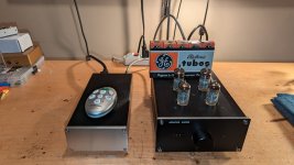
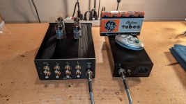
I had build it to compare noise produced by differents voltage regulators.

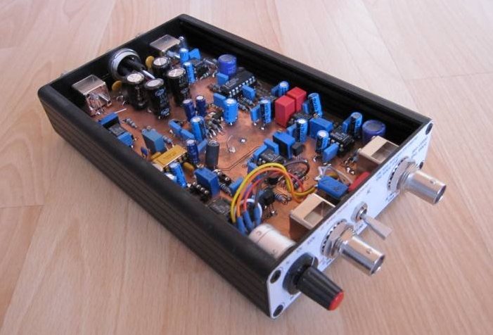
For a this use, the two functions are connected one behind the other, and a DC voltmeter is connected at the output of RMS/DC converter to
display directly the noise level measurement at input of the LNA.
This two function are indépendant but located on the same enclosure.

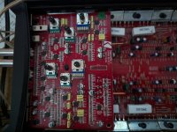
These tools works fine.So the RMS/DC converter described in the AN61 use an obsolete part, the LT1088.
This part is hard to find, and if you find one you risk to get it at very high cost !
Another issue with this part is it's unabality to doing measurements when signal level is too low.
So, it's practical measurement range is limited to about 10 to 100% of full scale.
On the other hand, the major advantage of this circuit is to allowing measurement at frequency up to 50MHz,
with signal with crest factor very high without degrading the precision.

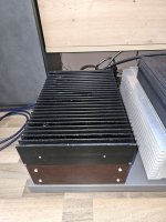
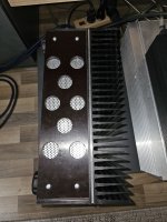
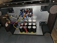
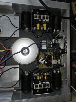
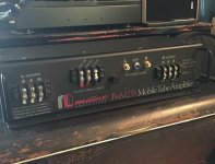
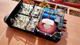
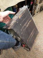
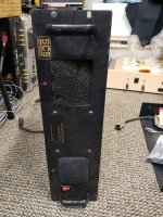
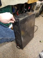
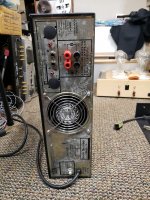
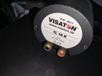
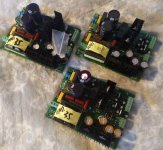
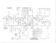
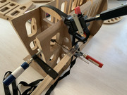
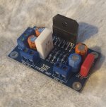
You can see what does look this first version below.It's a self made PCB.
[Pict1]
ERMSDCV1.jpg


Some weeks ago i had decided to make a new version of this tool.
I want to replace the LT1088 with a modern solution and an easy to find part, to make it more buildable.
Then i think it would be an interesting projects to many DIYers...Isn't it ?

Not many solutions exist to doing RMS-DC conversion, above at reasonable cost.
I eliminate the very known log-antilog converter (like AD736) because they are cosly, doesn't have
wide bandwidth, have big error with crest factor increase.

Nowadays, a good solution is to use a new IC from Linear Tech, the LTC1968 (again they !)
This relatively new IC use an innovative way to do RMS-DC convertion.
It allow very good bandwidth of up to 1MHz, very good precision of less than 1% and low cost.
The measurement precision stay very good with low signal level and medium crest factor.
The LTC1968 is also very easy to do work, only few parts are need to be fully fonctionnal.
The only issue is that it only exist in a very tiny SMD package (MSOP8), to require a good soldering tip.
So, unfortunatly for humans eyes it's quite often the case with modern electronics parts....


The main specifications i would ask for each functions of the new measurement tool are :

Common specifications:

* Powered by batteries (+/-6Vdc) or symetric DC supply +/-6V to +/-12V.
* Housed in low cost aluminium case Hammond 1455L1601.
* Standard Europe 100x160mm 2 layers PCB.
* No exotic parts.

1/ Low Noise Amplifier (LNA):

* High gain of 80dB (x 10 000)
* 10Hz..100kHz build-in -3dB pass-band filter.
* Equivalent input noise of about 500nVrms.
* BNC input and output.
* Overload detection.

1/ RMS to DC converter:

* DC to 1MHz measurement bandwidth
* High input impedance 1MOhms/10pF
* Ooscilloscope probe use for x10/x100 attenuation,
allowing extending measurement range.
* 1v/100mV or 1V/V sensitivity output.
* BNC output and output.
* Overload detection.
* AC or DC coupling input.


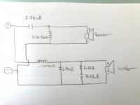
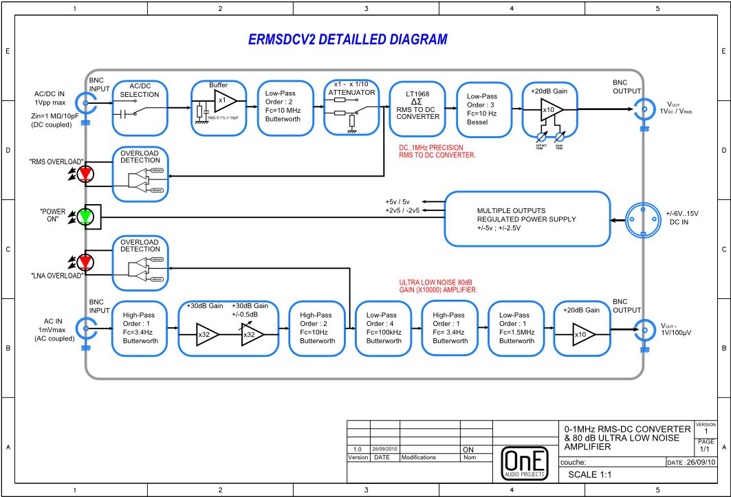
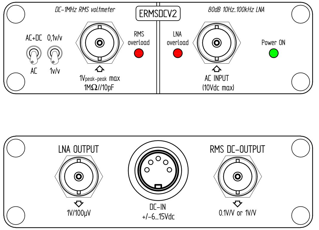
You can see below the functionnal synoptic of the new projects ERMSDCV2 with above features :
[Pict2]
synopticv2.jpg


The LNA doesn't change in the V2, just an overload detection is added, and the possibility to use SMD or DIP parts(dual-pattern).
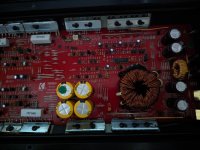
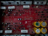
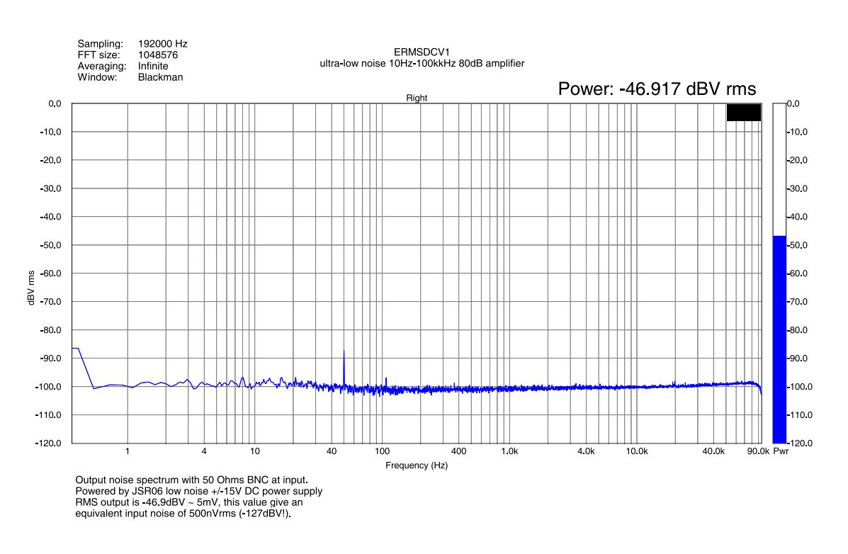
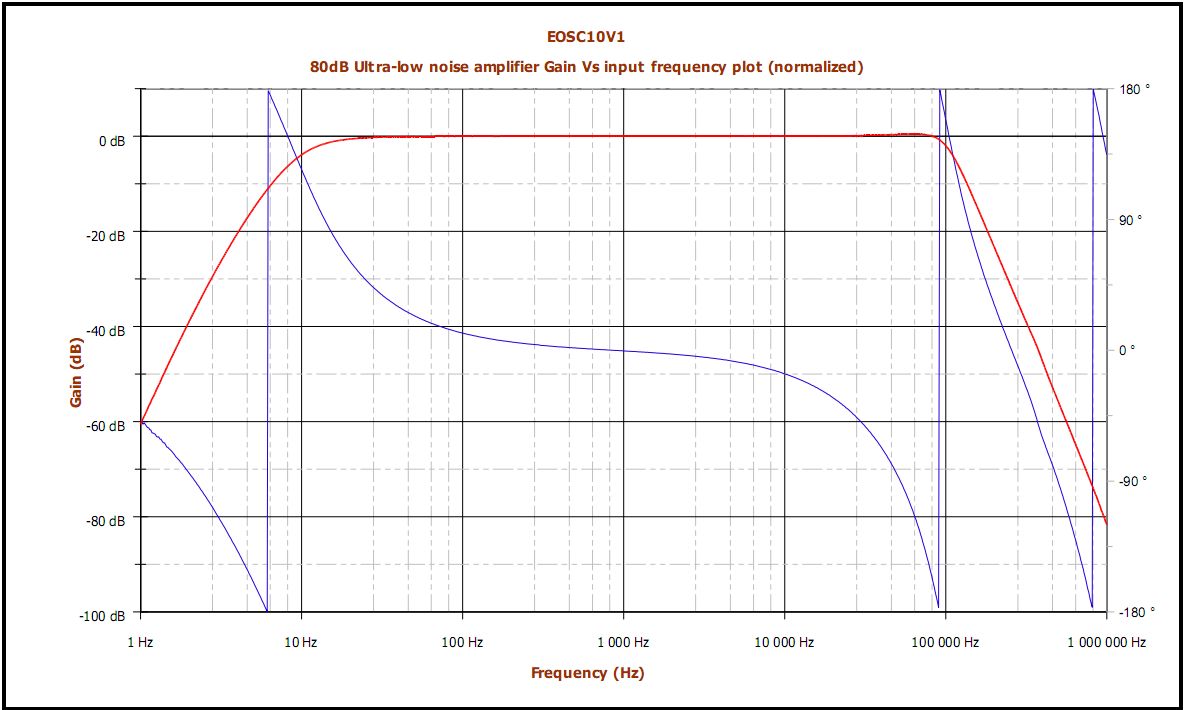
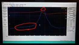
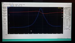
You can see below the resulting frequency response of the LNA, and it's own output spectrum with shorted input.
(It's not simulation results, but real measurements !)
[Pict3]
spectrum.jpg


[Pict4]
bodeplot.jpg


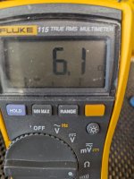
As you see, the measured output noise level of the LNA is about 5mVrms (-47dBV), so it's about 450nVrms reffered to the input (-127dBV)!
(It's the equivalent noise generated by a 150 Ohms resistor at 300°K !)
This very low noise level in this frequency band allow to do measurements in microvolt range. Like regulators noise, amplifiers noise and more.
To achieve this specs, shielding is very important ! An very good power supply or using batteries is recommanded for measuring this level of noise.
50/60Hz line magnetic field can be an issue, so all transformers must be far to the setup measurement, if possible.


The new schematic of the ERMSDCv2 is done, you can download it HERE (pdf file).
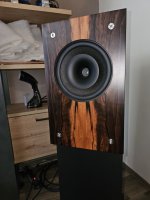
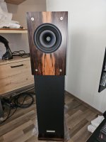
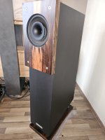
The final design in it's hammong box will look like this ;
[Pict5]
panelsv2.jpg


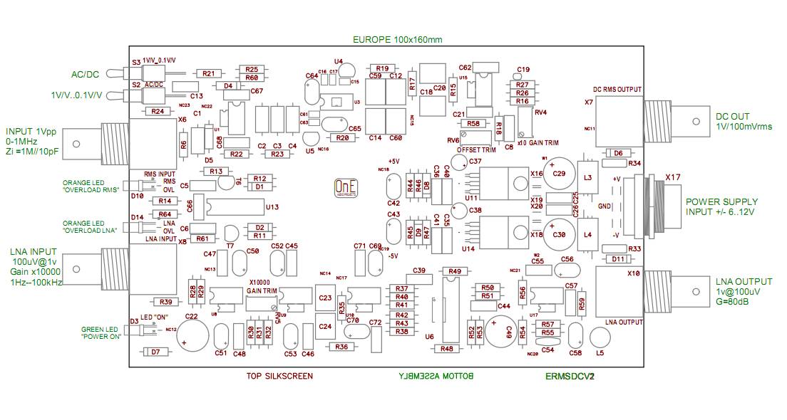
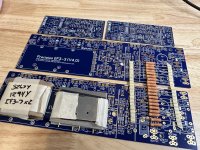
And the printed circuit boards will look like this ;
[Pict6]
ERMSDCV2imp.jpg


Actually i start to solder parts on the prototype PCB and wait to receive some missing parts.
Of course, i will post results as soon i will try it.
I hope that new projects will interest many electronics fanatic like me. ;-).

As for the "AN67 10kHz low THD oscillator" and "DIY CS5381 ADC" ,
when the project will be ok i will organize a PCB group-buy for this new design
if some DIYers are interested. 🙂
To follow soon...


Frex.

For Sale Wolverine EF3-3 Mini Package

Up for sale in this mini package:

  • Blue Wolverine EF3-3 w/ IPS board set
  • 24 Dale CPF 0.5R 1% 3W resistors
  • Finished set of pcb mounted aluminum heatsinks
  • Full set of Sanken 2SC3263Y/2SA1294Y Hfe matched output devices (sourced from highly trusted DIYA member)

SOLD including shipping within USA only ( payment via PayPal)

Attachments

  • IMG_0853.jpeg
    IMG_0853.jpeg
    796.4 KB · Views: 214

Shallco step attenuator questions.

I have this Shallco 47 positions switch for a long time but haven't got chance to really build it. My plan is to make a 100K series stereo unit, basing on the parts list provided by Michael Percy.

Since this is my very first time fooling with this switch, I'm a bit confused about some points, hopefully smart guys here could lighten me.

So I count 47 positions in total but according to the list there are only 45 steps, with last resistor ending at 44-45 positions. Does that mean I'll just leave out the last 46-47 positions on the switch unsoldered?

Also, are these photos below the correct way to solder the resistors in series configuration? I found some photos on Google but most of them were in ladder and required a ground ring.

Thank you!

IMG_0032.jpeg
IMG_0030.jpeg
IMG_0028.jpeg

Class D amp issue/need advice

Hi, I assume this is the place to ask for assistance/help with a problem I am having? Not sure if there is another thread that's for the sole purpose of trouble-shooting class d amplifiers?

Anyhow, I have an issue with my Icepower 1200as2 amp module. Just out of the blue it started switching from ON to STANDBY, even when a signal is present. When I assembled this amp together, I wanted (2) LEDS (Blue and Amber) to display when the amp is in the ON mode, then after a few minutes or so with no signal, the amber LED would come on. It had been working fine for a long time, then one day it started. So I unplugged the unit and pulled the top off to see if I could notice anything visually. Nothing stood out. I even disconnected and reconnected the connections that connect to various plug-ins. I then tried it again and it worked for a while, then started doing the same thing. This seems a little crazy to me as I did it once again by unplugging the unit for a day or so, then plugged it back in and it stayed working good for a longer time, but now it's starting to act up again?? I have no idea why! Perhaps someone may know of a solution, as I really don't want to trash it? Any help would be greatly appreciated! Thanks!

Speaker build measuring questions

Hello all.
I've built from plans before and some enclosures, but this is my first scratch build, and I have some questions.
The build is with a pair of Radian 5210 coaxials, in a 3ft^3 box, and a 4" vent. I have factory SPL graphs and the factory T/S numbers, but I decided to go all the way (within limits) and bought a Dayton DATS3 to get more precise measurements to work with. I also set up my UMIK-1 and ran some sweeps today, super close, right flush with the baffle to try to eliminate as much room interaction as possible lol. I tested in an unlined box, and next I'm going to test again with some decent degree of lining to tame things down a bit.
Here's my questions
1. I took T/S measurements both free air and mounted in my test box. Which set should I use for the crossover inputs?
2. The SPL graph is somewhat different from the factory test (these were matched and tested at Radian), which is understandable since my conditions are so different and they may have either tested free air of infinite baffle, I don't know. But does it make sense to keep playing with lining the box and adding fill until the reading looks as good as possible, and then use those plots in Vituix? It makes sense to me, but I don't know. I'll post some bad photos I took as I was struggling along today, FWIW. The first photo shows the factory results compared to mine, apologies for the amateur graphic arts display. The second is the woofer obviously, the third is woofer/tweeter, and the last includes the port. The reason you see two lines for each in the later photos is because I measured with and without a bunch of panels surrounding the box/mic to see if there was any improvement in taking some reflections out, at least in the higher regions. The most dramatic difference was in the 12-20k region, where the panels definitely smoothed things out a bit.
Thanks in advance.
Bryan
71304467044__90CE9E9C-D8C8-4589-ADEB-0C49A4049E62.jpeg
71304068296__89DFCC59-81B6-4DDF-BDC4-0246BCCC662E.jpeg
71304314181__D86298B9-F67A-4404-BD4F-7DF9EB06D95A.jpeg
71304122984__AAC82565-E321-40D2-BA3B-04F7F6F05252.jpeg

"The Wiener" TPA3118 amplifier card

== UPDATE - MARCH 9 ==

PCBs are shipped! Group buy is now closed.


== UPDATE - MARCH 3 ==

Inductor crisis averted! For 4/6 ohm builds, I'm using 10uH Sagami 7G14D-100M. This inductor is getting bought/shipped separately and costs more than the ICE Components part, so pricing has been increased for configurations that use 10uH inductors. Here's the current price list:

4 ohm and 6 ohm card, fully built = $95, w/filter kit = $105.
8 ohm card: $90, w/filter kit = $105
16 ohm card = $95.

If you've already paid, don't worry, I'll absorb the cost difference.

Not many days left to get your orders in. I'm stopping the group buy as soon as the PCBs ship from elecrow, and making my Mouser/Digikey orders.


== UPDATE - FEB 17 ==

Group buy is on! I'll be accepting payments for ~3 weeks, or however long it takes me to get a prototype ordered/built/tested/verified. Once that's done, I'll close the door on payments and order PCBs/parts.

My paypal address is (posted as an image for spam reasons):
[REMOVED - group buy now closed]

Remember to pay in $CAD - if you pay in $USD you're overpaying.
If you're ordering a fully built amplifier, make sure to specify the load impedance (4 ohm, 6 ohm/TI, 8 ohm, 16 ohm)
If you're ordering a PCB + microcontroller, make sure to specify separate-in-a-bag or soldered on - price is the same either way.


Example prices:

- Bare PCB ($8) with TPA3118 ($15) and microcontroller ($2) installed, shipped internationally ($10.50) = $35.50 CAD
- Two fully built/tested amplifiers, 8 ohm ($90) and 16 ohm ($95) plus two hardware/thermal kits ($10x2) = $205, shipped to the US via Small Packet Air ($15) = $220 CAD.

If you're shipping full amplifiers internationally, or shipping within Canada, use the Canada Post rate calculator and message me with the quote so I can confirm it.


== The Weiner ==

AudioLapDance put out a request for a highly configurable TPA3116 card in this thread:

http://www.diyaudio.com/forums/class-d/267039-proper-tda3116-pcb.html

One day I was stuck home in a snowstorm, and decided to bang out a card design that met his requirements. Soon several other people started throwing in suggestions and requests, and the design evolved into something we all feel pretty good about. AudioLapDance himself proclamed "we have a wiener!", and the name stuck.

Here it is:

Top PCB:
eE4Gd4M.png


Bottom PCB:
qvNr0H9.png


Schematic:
c2LE8js.png


== Features ==

- Small size (5x10cm)
- TPA3118 amplifier IC (more on this choice below)
- Everything is easily and quickly configurable - AMx and MODE pin settings, gain setting and master/slave mode can all be set with DIP switches, and a trimmer pot is provided to allow PLIMIT voltage adjustment.
- 2 stereo channels. The card is configurable into PBTL mode if you want, though unlike DUG's card it's primarily intended to be a stereo design.
- "Wideband" PVCC decoupling, using multiple capacitors chosen to provide a low PVCC impedance from "audio to VHF"
- Additional decoupling on the AVCC pin
- Snubbers before and after the output filter.
- Good quality output filter (ICE Components 1D14A, Epcos 32529J film)
`--> Multiple filter options available for purchase: 4 ohm (10uH/1.5uF), 6 ohm (10uH/0.68uF, standard TI configuration), 8 ohm (15uH/0.47uF) and 16 ohm (33uH/0.22uF)
- Good quality film input caps (2.2uF EPCOS film), footprint will also accept 1210 ceramic capacitors and through-hole bipolar electrolytic capacitors.
- Microcontroller-controlled power up sequencing, with an adjustable startup delay to mitigate turn-on pops with unbalanced sources or large input coupling caps.
- Connections provided for a standby switch and a power LED.
- Good ESD protection on all inputs.


== So, uh, why the TPA3118? ==

To make room for decoupling caps.

The TPA3118 is actually the exact same IC as the TPA3116, but with a bottom side thermal pad for PCB heatsinking. Provided you can sufficiently heatsink the TPA3118, it's capable of the same output power and audio performance as the TPA3116.

In this design, the PCB has lots of thermal vias and an unbroken ground plane under the TPA3118, providing a lower thermal resistance than the heatsinks you find on most of the TPA3116 cards out there. By bolting the card to a metal enclosure and putting a thermal pad between the PCB and the chassis cooling can be even further improved.

With no top side heatsink to interfere with them, decoupling capacitors can be brought very close to the TPA3118 pins for improved performance. Achieving the same electrical performance with a TPA3116 would require the heatsink to be machined to provide clearance for the close-in decoupling, or a small heatsink barely larger than the TPA3116 itself which would not be as thermally effective as the PCB here.


== Cost ==

For bare boards:
- Bare PCB: $8.00
- Add programmed microcontroller, either in a static bag or soldered to PCB - additional $2
- Add a soldered on and tested TPA3118: additional $15.
- Shipping is $8 to the US and $10.50 international for up to 4 PCBs, using Canada Post "Light Packet" service. Within Canada, use the Canada Post shipping calculator for a 6x9x0.5" parcel that weighs 1/4lb, shipped from postal code B3Z 1R3, add $3 to whatever it spits out, and PM me to verify.

For fully built/tested amplifiers:
- 4 ohm or 6 ohm: $95 CAD. With filter kit (allows reconfiguration for 4/6/8 ohm options) = $105.
- 8 ohm: $90 CAD. With filter kit, $105.
- 16 ohm: $95 CAD. Add $10 for an 8 ohm filter kit and $15 for a 4/6 ohm filter kit.
- Chassis mounting kit (thermal pad, standoffs, stainless M3 hardware) = extra $10
- Shipping for up to 3 assembled/tested boards to the US will cost $15 using "small packet air" service.

For shipping elsewhere or using a different shipping method, hop on Canada Post - Mailing, Shipping, Marketing, Shopping, Sharing click "find a rate" and calculate the shipping cost for a 6x4x3 inch box, weight 1lb, from postal code B3Z1R3 to wherever you are, then add $3 for packing supplies and PM me to verify.

Thanks for your interest!

Compression driver and horn selection

Hi all,
I am going to build a PA speaker set to complement my 4 12" subs (fEarFul from greenboy).
I am thinking of a column speaker that will look like (and hopefully sound like) the RCF nlx 24-a
So a beaming speaker featuring 4 8 inch woofers (dayton audio mb820-8 probably). They sound nice and have pretty high efficiency of 94db.
I will use biamping for this set, so filtering is no problem. I would like to cross over around 1.5khz.
I have some trouble selecting a good sounding tweeter and Horn (CD, 90×60)
There are so many models and brands!
My goal is hifi sounding highs, smooth and brilliant with smooth roll off to the sides. It does not have to hit 20kHz, up to 18 is fine.
Colouration should be minimal.
I have qcs rmx amps to drive both woofers and tweeters
I don't have a big budget, I am thinking of something in the 100-200 euro price range per side.

Any tips welcome (also for alternatives for the daytons)!

Return to Vinyl - and a decent turntable

I have been seriously considering getting back to vinyl. The reasons for this sudden change in listening tastes are documented in my other threads, which I will partially quote here for convenience. There seem to be no other threads on getting back to vinyl, so some may find my experiences here useful, hence these posts.

I assure everyone following this thread that I have everything in place to purchase a decent turntable, I hope to be traveling out of the country to place where they sell records and record players, and purchase one and bring it back: not shipping costs. Yes, a turntable that will not destroy vinyl or even have an such accusations leveled against them.

The steps, then:

  • Experimenting with a cheap record player and learning all I can
  • Selecting a real turntable to purchase
  • Purchasing the thing
  • Buying records and enjoying imperfect sound for a while (I haven't got forever)

Milbert BAM-235AB

Recently acquired on of these beasts, been lusting after one since I first read of their existence back in the early 90's. It arrived with all 4 power supply bipolar transistors blown open, rather than sourcing replacements I converted it to use TO-220 packaged logic level MOSFETs, for reliability's sake. It now works well but I can't seem to locate a manual online for it. Milbert's website says to email them and they will provide one, but I haven't heard anything in nearly a week's time and their phone number isn't working either. I know it's a long shot, but has anyone had any interaction with them or have they slowly faded away?

Attachments

  • milbert.jpeg
    milbert.jpeg
    89.5 KB · Views: 151

Touch sensor on/off switch

Hi. I've built myself an amplifier, and am happy with the results. In terms of switching on/off I run 230V mains into an Audiophonics soft start module, which has "switching by fugitive pushbutton low amperage or by trigger 2-12V".

So I have a push button switch attached to the +/- contacts of the soft start module "switch" connection (it also has separate +/- 'button' & 'trigger' connections).

I'd like to replace the push button with a touch switch, but I don't understand enough to feel I can ask the right questions.

I bought a non capacitive touch sensor switch - this needs a 3 - 30v DC supply. The sensor has 3 connections DC + In, Gnd, DC Out. I have connected it in place of the push button - well I connected the soft start 'switch +' to the DC + In, and the ss - to DC Out. This allowed the amp to power up, but no on/off unless I switch on/off at the mains.

I expected this to work, but am nervous about damaging equipment if I start playing around with other connection configurations.

Can anyone help?

Thanks

Russian UHF amplifier tubes

Dear all

I stumbeled across a couple of russian UHF triodes, small ceramic tubes
- ГС-14, GS-14
- ГС-4, GS-4
- 6C17K, 6S17K

These seem to be very linear triodes, working at moderate voltages, direct heated.

Does anybody know anything about their use in tube amplifiers? They could be used for the preamp stage probably.

Thanks for your answers.
Thomas

Slot loaded vs sealed subwoofer table

Hi guys!

I don’t wanna get redondant with my post but I was reading my other thread about my living room subwoofer and I wanted to get a little informations on slot loaded-ish subwoofer.


So I designed this living room table subwoofer. But I’m not sure how to handle/make the grille

Here’s the original design with the grille:
Capture d’écran, le 2023-01-03 à 01.20.58.png


Or I can go east and make a fabric grille with a frame like this under the fabric:
Capture d’écran, le 2022-12-11 à 10.57.35.png


But I feel like the grill would be very heavy. And as I want to not have visible hardware (as much as possible) and want to protect the woofer from everything that can happen in a living room with a 2yo.

While wanting to keep vibrations to a minimum, I sketch this version:
Capture d’écran, le 2022-12-11 à 10.49.09.png


IMG_1351.png


I have 2 Dayton um15 for the subwoofer. Will be Powered by 2 behringer inuke 6000.

So I wanted to have feedback / advice / opinions / facts on the slot load design.

The second version could have 1-2-3 slots depending. As long as the top stays solid for table purpose.

What would be the minimum distance between the two driver in order not to be considered a slot and for not having any “down side” of such design?

Should I stick to the 1st with grille?

Table is 16.5x16.5x40 external dimension.
Pannel are already cut in Baltic birch for the first design, but I have some left so I can make minor adjustment for the slot load design if it’s best.

I’ll gladly add any forgotten information if you guys have question.


Thanks!
Projects by fanatics, for fanatics
Get answers and advice for everyone wanting to learn the art of audio.
Join the Community
507,797
Members
7,888,840
Messages

Filter

Forum Statistics

Threads
406,261
Messages
7,888,840
Members
507,797
Latest member
Moza