Quiet 12CX Open Baffle w/ DSP Build Log

I've settled on Eminence Beta 12CX and PRV D290py-S compression drivers in a JE Labs style open baffle with a MiniDSP crossover. My design goals are to create a mid-range focused system for low to low-moderate listening (paper thin walls in the new apartment). So far I've only built mono systems so I'm excited to explore soundstage and imaging! I have headphones for bass heavy music, but I'm interested in exploring more jazz, soul, world and opera with this system. Note: I cannot hear past 16000hz.

I'm constructing a rig to measure this speaker 6' off the ground in my back yard. Past this iteration I'm interested in exploring felt baffles with large round over edges, but for the moment I'm content learning the ins and outs of DSP.

I just ordered two 2x15w boards from classdaudio.com to power the 12CXs/tweeters, but I also have an inuke1000 at my disposal if I need more power for the woofers. Question: I like dynamic systems, if I use a more powerful amp to power the woofers and EQ nulls will I loose dynamics? The woofers are 97db with 250watt RMS power handling. The inuke puts out about 160 watts into 8 ohms. Like I said, I'm not trying to get super loud with lean bass. Any tips for designing a DSP based system for quiet listening?

drivers.jpg

My first DIY amplifier 20 years a go

Hello
These was my first DIY amplifier , I built about 20 years a go .
Now I think to rebuild it . From beter quality parts .
Any comment welcome .
When firs I built it I used one pair power transistors but after I added one more pair which brought a lot of improvement in the sound .
More dynamic , more bass , I used +/-56V power supply with two pair 50 000uF Mepco capacitors .
I post the schematic you can take a look . No need for preamplifier , just a 10K pot. . On the input is better to use a bit higher value capacitor .
One more time any comment ,advise welcome
Greetings

Attachments

  • first diy amplifier.jpg
    first diy amplifier.jpg
    59.3 KB · Views: 18,033

MOSFET mystery

Working on a smps.
A pair of N channel mosfets are testing as P type?

Using Fluke 115. Red probe in red socket. Black probe in black/common socket. Meter set to diode mode.

Removed a pair of mosfets marked 1L02AB FDP

26N40 from the circuit.

The pair of Mosfets are still screwed to the single heatsink. Mosfet printing facing me.

I did the test where I short the left and center pins. I put black probe on right pin and red probe on center pin. I get OL. While keeping black probe on right pin, I put red probe on left pin and get OL. After a few seconds I move red probe from left pin back to center pin and still get OL.

Now, even after I short the left and center pins, if I switch the probes put the red probe on the right pin and black probe on center pin, I get .49v. The center pin never measures OL even after shorting the left and center pins when measured like this.

This happens with both mostets. But there is no short from the left pin to the center pin (gate to drain).

What's the deal?

Connecting DAC to a tube phono preamp

Hi, I recently acquired a tube phono preamp and I don't want to use it just for my turntable but also for my digital sources. As far as I know, I can achieve this by feeding the signal from DAC through a reverse riaa circuit (R-riaa) to the preamp. My problem is where should I add the voltage divider? Basically there is two options, adding between the DAC and R-riaa or between the R-riaa and the preamp.

In addition, although I can find somewhere to purchase the R-riaa, I can't find anywhere sell the voltage divider and I assume I have to make one by myself. My demand for the voltage divider is simply the following. First, it is able to reduce 2V from line stage to 200mV so that it doesn't overload my preamp. Second, I prefer it to have rca input and 3.5mm rca input jacks. In this case, what material do I need? I haven't diy before but this seems to be a easy project.

By the way, does anyone have the experience of doing similar thing, what is your impression about the result and what suggestions you would have for me?

VTVM or FETVM?

Inevitably during tube builds it becomes obvious that at least 10 megohms/volt DC is needed, especially on grid circuit measurements.
So this guy, from an SS background where 20k /volt was fine, had to tool up. Went online and purchased eico 232 VTVM and micronta 22-220 FETVM.
Had to spruce up the eico a bit, HCL on the rotaries and battery eliminator- also replacing the 1% resistors that were way out tolerance- the ohms scale was egregiously off. Micronta, the other hand was pristine inside- initial readings checked out- but cleaned the rotary for good measure.

After using both-
Can say that really wanted FET meter to be the go-to, but it's sensitivity isn't as good as the VTVM when on amp grids & especially tube receiver tanks.
Of concern is decay in readings w/ the FETVM... goes up to a point, then begins to fall on the above examples... Could be a prob w/ the meter?? It doesn't have same issue other less sensitive areas. Also, meter response is ketchup bottle slow compared to the eico, which snaps up immediately w/ reading.

These are my shallow impressions thus far w/ these 2 analog meters. I'm sure digitals are different, but I prefer good analog- 2% accuracy is good enough.
Moreover, can easily identify low freq voltage fluctuations w/ analog V digital meters- JMO
What are members here using?
Jim

Push Pull vs Normal Distortion Compared

Having never seen an actual comparison of the same cabinet used as a push pull (PP) compared to a normal forward facing pair, decided to do it myself.

Since comparative push-pull and push-push distortion measurements are hard to locate, thought it would be good to reference Mark100's more recent work here too in post #27:

https://www.diyaudio.com/forums/sub...normal-distortion-compared-3.html#post6609651

PP proponents claim large reductions in distortion due to the cancellation of the differences caused by non-symmetrical cone movement, but without a comparison of the same speaker in the same cabinet, other design features such as a front plenum or horn loading make the reductions hard to quantify.

In my test, a suitable sized rock was chosen after an extensive 30 second observational period and placed in the enclosure on top of some rags to keep the internal cabinet volume the same when the cone was reversed for PP testing. The speaker with the magnet facing forward has the polarity reversed, both cones move forward when positive voltage is applied.

We had a perfect day for testing, (other than smoke from the many nearby fires, and 100 degree temperature) ambient and wind noise were very low. Testing was done at 2 meters.

Using LAB12 drivers, although second, fourth, and sixth order harmonics were greatly reduced by push-pull loading, the second harmonic sometimes increased, resulting in the THD (total harmonic distortion) not always significantly changing, as can be seen in the 20 Hz 49 volt test results .
That said, distortion figures were reduced by 50% or more at some frequencies.

Since the frequency response and output of both the PP and standard cabinets were almost identical, an A/B listening test was simple, just swap the speaker cord and short out the unused cabinet.

At lower power levels, where the LAB12 is quite clean, no difference could be detected. When pushed at a power level where distortion could be noticed, the most distracting artifact was the audible vent noise from the reversed magnet structure of the PP. The lack of the second harmonic, an octave, made the now predominant third harmonic distortion more apparent in the PP cabinet. This is a music related thing, the third harmonic, being a perfect fifth, may sound OK with some compositions, while sounding “wrong” with others.

Although the technical side of me says reduction of distortion of any sort is a good thing as far as a reproduction system is concerned, both my old ears, and a college freshman apprentice thought the push pull cabinet sounded less “musical” when pushed hard.

Listening tests were not extensive, as we had to put the speakers away due to rain, the first in months. I put the speakers back to normal, and put the grill back on. Today I realized we had not done listening tests on the sealed versions of the cabinets. Also forgot to take an amplitude response for the PP ported cabinet, but judging from the response curves of the sealed PP cabinet compared to normal, looks like the frequency response would be little different below 250 Hz. The sharp dip around 300 Hz in the “Raw 2x12” is a port resonance.

The distortion screen shots are in posts 3 & 4.

Addendum:
The Lab 12 DC resistance and cabinet minimum impedance is almost the same, 4.29 ohms per speaker, 2.145 for a pair of Lab 12s at 49 volts is about 560 (rather than 400) watts per driver, 282 (rather than 200) watts per driver in the 38.4 volt test.

Art

Attachments

  • Lab Cabs.jpg
    Lab Cabs.jpg
    56.1 KB · Views: 1,765
  • PP & Distortion Calc.png
    PP & Distortion Calc.png
    78.1 KB · Views: 1,687
  • Raw Response.png
    Raw Response.png
    66.7 KB · Views: 1,649
  • Computation for THD.png
    Computation for THD.png
    18.3 KB · Views: 1,646

Woofer for a small box WAW / FAST with Peerless TC9FD18-08

I have a pair of Peerless TC9FD18-08 drivers. I've tested them in a 3 L heavily stuffed closed box and they sound fantastic. The best mids/highs I've heard.
And now I want proper speakers made with them, conventional 2.0 design. I want to preserve as much of the frequency range produced by the TC9 drivers as possible while providing assistance in the low-end range.

I need a woofer/subwoofer that will work in a reasonably sized vented(or with a passive radiator) box(around 10-12 L not more than around 15 L) and play up to around 350 Hz.
Also I would like to select something that will go as low as humanly possible with a 5-6.5 inches driver and reasonably sized box.
I plan on listening my future speakers at very moderate levels, few Watts of power, not more than that. I will prefer low-end reach to a huge excursion and power handling for sure.
I will listen to them in the only sweet spot behind my desk.
2nd-order crossover will be active and the speakers will be bi-amped, so no sensitivity match required between woofer and fullrange. HP filter with high Q to assist with the bottom end and to limit the excursion can be easily added.

I'm eagerly waiting for your recommendations.

I've seen a FAST design with TC9FD18-08 and RS225-8, but that 8-incher requires a huge box that won't fit my current living space.

Possible Tysen FAST/WAW

I’m very much enjoying a simple box with a pair of the MA SOTA drivers but now I’m looking to downsize my main system and the Tysen/FAST system piqued my interest.

The Alpair 5.3 looks like a little detail monster so that is my choice for the mid/high portion

For the bass I’ve always liked the look of the SB15SFCR39-8 from SB Acoustics (https://doc.soundimports.nl/pdf/brands/SB Acoustics/SB15SFCR39-8/SB15SFCR39-8.pdf) A pair in an opposed side firing,push push design but sealed. This might be nice as they have a lovely deep roll off for tuneful lows In a sealed box.

Am I nuts for going sealed? Will the Alpair 5.3 keep up? What sort of positioning in the room should a Tysen have with its side firing woofers? I’m used to much larger speakers 15/10/1.4CD inch drivers, but have lost WAF. I know the A5.3 is renowned for detail so I’m wondering what sort of picture will this design can paint?

Any thoughts would be greatly received.

Attachments

  • DAC64BB5-5D79-4CFC-9135-A5193D7B603D.jpeg
    DAC64BB5-5D79-4CFC-9135-A5193D7B603D.jpeg
    135.3 KB · Views: 193

Restoration McIntosh ML-4c

I am in the process of updating the drivers on the ML-4C. I have redone the crossover schematic to match the crossovers documented in the ML4C service manual(also attached). The new drivers are the MDT40 and MDM55 made by Morel as recommended by Roger Russel in his restoration info attached to this thread, https://www.diyaudio.com/community/threads/restoring-mcintosh-ml-1cs.380129/. The manufacturer published 0 degree FRD/ZMA for those drivers are also attached. I also attached the SPL graph from VituixCAD for the upper/lower midrange and tweeter reponses and the VituixCAD file for this speaker system(change the extension on the ml4c_all_speakers_schematic file to ml4c_all_speakers_schematic.vxp, in order for it to load into VituixCAD). The Woofer and Midrange schematic is included but is detached from the main crossover because I do not have the FRD/ZMA for those old drivers. I am posting this info hoping someone has the frequency responses of those drivers to verify the 1.5K crossover and overall axial response. If not available and I've searched everywhere, likely I will have to measure those drivers... but being the ML-4Cs weigh more than a fridge, I'm not looking forward to that.

I had previously updated the crossover components in 2021(pandemic project) with the same original schematic values and brought life back into those speakers.

Before:
ML4C before.jpg


After:
ML4C After.jpg


I'm wanting to update the drivers so I can get some more life from these wonderful speakers.

Any comments on the crossover are welcome. Sadly, Roger Russel is no longer available to us.

Attachments

  • Poll Poll
High performance current drive power amplifier

Does this interest you?

  • Yes, I am interested to see where it goes.

    Votes: 26 48.1%
  • Yes, I want a DIY version of something like this.

    Votes: 20 37.0%
  • Yes, sign me up for a finished amp.

    Votes: 4 7.4%
  • No, i'd rather discuss some cables.

    Votes: 4 7.4%

The discussions around current drive amps has been going on for years, but very few are ever built. Any active speaker with dedicated amps for mid and tweeter might potentially benefit from it, and also FR drivers tends to have a huge benefit from being powered by a current drive amplifier.

In theory, a current drive amplifier is just an amplifier with infinite output impedance. A voltage drive amplifier, on the other hand, is an amplifier with zero output impedance. As all speakers generate their force from current, and not from voltage, having the speaker fed by a controlled voltage is in many senses a step away from controling the driver directly. This is not suitable for all speakers, certainly not if you have 100% current drive, but for some situations, a current drive amp just might be the right choice.

One of the most obvious situations where a current drive power amplifier should be considered is for midrange and tweeter compression driver/horn-combinations. This is sort of the basic idea behind this project, so one of the main focus points is low noise and low distortion. High gain and high power however, is not a priority.

To achieve this, the idea is to stack many small signal op-amps in parallell on each output. By manipulating the balance of the circuit, the level of current drive (or output impedance if you will), the amp is adjustable between current drive and voltage drive. At most, it should be pretty much 100% current drive, and at the other end of the scale, it should be close to 100% voltage drive.

Other priorities are noise (less than 10µV unweighted) and, of course, very low distortion. We are looking at adding local voltage regulators for each op-amp to better achieve this. We are probably looking at upwards to 80W/8 ohm and 160W/4 ohm, but as a current drive amplifier does not increase the power when the impedance is reduced, these numbers are slightly theoretical.

Is this something you guys find interesting? Should I keep you updated on this?


EDIT: And before you post your opinion on why voltage drive is better for a complete loudspeaker. Yes, that is why current drive is only used successfully in active systems, and especially for mid and tweeter, (above Fs) which is also the aim for this project.

Ian Canada RaspberryPi Streamer

SOLD


This is a completed RaspberryPi based streamer with top of the line parts from Ian Canada. It is loaded with Ropieee software but could be changed out to a different software. Some DIY knowledge would be needed to manage that and set it up on a new network. A great sounding unit that really made me realize the difference a streamer could make in the sound quality of a system. So why am I selling it then? I'm going to move up to a significantly more expensive streamer in hopes of further refining my system.

Price is $450 including shipping CONUS only and payment via PayPal friends and family option.

This is significantly less than the cost of all the components that went into the streamer. I have those parts listed out below with associated new costs. I am not looking to sell individual components and will only sell as a package

Compontents:
iFi iPower power supply - $70
RaspberryPi 4b - $80
FifoPi Q7 flagship 768KHz I2S/DSD/DoP FIFO with isolator - $189
HdmiPi Pro Flagship HDMI transport interface - $125
TransportPi AES, Flagship AES/SPDIF stransport - $139
PurePi 5V+3.3V ultracapacitor/LifePO4 battery power supply combo - $86.00
UcConditionerMkII 3.3V - $69.00
MonitorPi RaspberryPi OLED audio display/analyzer - $49.00
Total cost of parts new - $807

Attachments

  • 1.jpg
    1.jpg
    583.5 KB · Views: 457
  • 2.jpg
    2.jpg
    677.1 KB · Views: 439
  • 3.jpg
    3.jpg
    680.4 KB · Views: 534
  • 4.jpg
    4.jpg
    692 KB · Views: 371
  • 5.jpg
    5.jpg
    858.5 KB · Views: 394

Pair PP Output Transformers==Unused

Pair of Output Transformers for Push-Pull Amp. Approximate values are 1600-1700Pri Impedance to 4, 8 and 16ohm secondary. As you can see in the images, there is also what looks to be a second output winding with the green, green/yellow stripe and brown/white striped wires. I am not sure what it could be used for. Transformers are heavy at app 7.5lbs each. Wires have never been soldered. $150obo plus $40 shipping in continental United States.

Attachments

  • IMG-2590.JPG
    IMG-2590.JPG
    75.3 KB · Views: 183
  • IMG-2586.JPG
    IMG-2586.JPG
    91.3 KB · Views: 194
  • IMG-2587.JPG
    IMG-2587.JPG
    54.4 KB · Views: 193
  • IMG-2588.JPG
    IMG-2588.JPG
    57.5 KB · Views: 166
  • IMG-2592.JPG
    IMG-2592.JPG
    76.1 KB · Views: 179

Modern capacitor over voltage, how high and for how long?

I’ve been rebuilding a few tube radios that I own. I realize that our line voltage is a bit higher than it was back in the day, so I am installing a thermistor on each of them to bring it down a few volts and I’m even open to adding a large resistor right before the primary winding to bring it down a few more.

I know that many of the capacitors from back in the day had both their working voltage and a peak voltage stamped on the can. I replaced the caps in this particular radio were rated for 400v and 450v. I replaced them all with 450v. I measured them on power up and the voltage shots up to 480-490v on all three caps and then settle at about 380v on the original 450v cap and 350v on the two caps what were 400v rated caps. So that means the two 400v caps were seeing nearly 20-25% higher than rated voltage, granted only for a few seconds. These originals don’t have a peak voltage printed on them.

I looked on the spec sheet of my replacements and couldn’t find anything on peak voltage. I’m using Nichicon CA, and another very good quality Nichicon along with good quality Panasonic, all 105 c of course. I haven’t run into an issue yet, but I was just curious as to how high these newer caps can go. If I were to swap the 400v rated caps with 400v rated, could the new 400v caps see that 480-490v for that several second duration like the vintage caps could?

Dan

VFET Chassis limited production run

I was the fortunate winner of the Sony VFET essentials kit auctioned yesterday at BAF22. So, naturally, I immediately contacted Gianluca of Modushop to beg for a chassis - like the gorgeous limited run done for the lottery. Gianluca amazed me by replying at what must have been the closing time of the bar opposite Burning Amp - in the wee, small hours…

Gianluca, who I hope will see this and confirm the following, said he would be prepared to do a small production run for a minimum of ten chassis. He suggested we start a thread and that is what this is - a list of interested parties prepared to commit to buying one or more VFET chassis from Gianluca. I am not offering to head up a Group Buy but simply hoping we can get to ten or more chassis orders here and then contact Gianluca with orders.

Name / Number of chassis wanted

derekr 3
  • Like
Reactions: Gianluca

3 way SB Acoustic towers - Build advice

Hi All,

Looking to build a nice set of 3 way floor standers.
I have a large room, approx 50-60m2, so looking for a decent size speaker to cover it.
Will be running a Denon X3800h (or extra amp if required when going passive)

I have been doing heaps of research to find a design, but i'd get stumped with massive freight costs, or unable to buy the driver etc.

So I have decided I'd like to build a 3 way, SB accoustics build, mainly because I can easily source the drivers in Australia.

I have tossed up the idea of active vs passive, was thinking maybe a couple of Hypex amps. So i could do a bit of dsp etc, if required.

I had nearly decided on a set of Zaph 12.3, but I'm undecided, thought i would ask some advice before deciding.
The physical size here is no worries.

So my decision basically comes down to active vs passive (1.5-2k worth of hypex amps before i even start the build) vs designing/testing crossovers and buying an amp if needed.
I don't mind either way honestly.

Then it just comes down to drivers. I do like the idea of having the 12" low end, 6-7" mid and tweeter.
I've seen a few designs that have the likes of, SB29RDNC, SB17NRX, SB34 variants.
If i went passive and crossovers costs didnt get out of control, i could probably stretch the driver budget a bit higher. EG. Satori midwoofer, TW29R tweeter

Going passive will require me to ask a lot more questions on here as its been years since i have dabbled with speaker building.
I've got a Umik-1 & DATS V2. Happy to learn whatever programs needed to do sims.
I've got plenty of access to panel saws, CNC routers etc, so i'm all good for the woodworking side of things.

Where should i go from here?

If you were in the same boat, what would you build?

Thanks so much in advanced!

Doubt about compressor operation

I'm designing a compressor and everything is quite clear to me, apart from one thing relating to the attack time:
a thought to which I cannot find an answer, as the opposite condition is generally assumed: attack time shorter than the threshold trigger period
What happens if the input signal goes below the threshold before the attack time is over? Will it reset compressor starting the release curve or will the reduction (compression) continue to rise until the attack time is completed even if the threshold is no longer triggered and then goes into the release curve?
Thank you!

Are they all badly designed?

Hello everyone. I've been digging on Youtube and found a Mr. who designs, builds and measures other builders' speakers.
I see that he performs measurements of different well-known brands of speakers, finding defects in their frequency response and in turn making modifications in order to improve them.
I see brands like KEF; B&W; Klipsch; paradigm; Focus Chorus; Etc finds them poorly designed. This is so?. The big manufacturers do this on purpose? Is it good or bad to get a speaker to have a flat frequency response?
I have a B&W DM602, and although I find it too analytical and a bit bright, I don't see it as a bad thing, on the contrary, I like it.
Greetings to all.
https://www.youtube.com/@GRResearch/videos

Mixing amplified sources for aviation headsets

Hey guys,

I'll start with a little background. I'm a helicopter pilot by trade and one of my day to day jobs is flying digital surveying flights. Essentially flying a grid pattern over specified areas for up to 8 hours at a time. I adore my job, but there is no doubt it gets a little tedious without some tunes or an audiobook to focus on. Recently I dropped some considerable cash on an in-line Bluetooth adapter for my helmet. However, the audio quality is dismal. Well suited to phone calls, but that's about it.

I've decided to try and build my own Bluetooth receiver. I've been experimenting with an ESP-32 and an I2S DAC acting as the audio source. This is working well. However, I'm a little bit stumped on how to feed my amplified music into my headset without backfeeding the helicopters intercom system.

The basic requirement is theoretically simple I think: I need to overlay my amplified music on top of the amplified signal from the helicopter without cross talk. Additionally The helicopter audio needs to pass through even if my Bluetooth system is not powered.

I'm not entirely sure how to approach this problem.

I figure I have two options: I can mix the two signals, or I can switch between the two signals.

I think mixing is the more technically correct solution. If something goes wrong with my hardware it's less likely to mute the helicopters intercom system. But switching between the amplified sources may be the more robust solution, however it would have to be carefully designed to automatically switch back to the helicopters audio when it detects audio on the intercom or if the Bluetooth battery dies.

Anyway, I'll cut to the point:

I have two amplifiers and one headset. What is the best for me to connect both amplifiers to the single headset without damaging anything? Is it better to switch back and forth, or is it possible to mix both amplified sources? What ICs or circuitry should I be looking at?

Thanks a ton for letting me pick your brains, guys. I really appreciate it!

Amp flashing on and off very fast on power up

I have an Audio Apex CAB45 that stopped working. When I try to power on with 12v it only flashes on and off very fast. However it will power on and stay on with low power at about 9v. No blown fets and no visible damage to any components. Does anyone have any idea where I should start looking? Any chance it could be a relay? I also do have another of these in working condition that I can use to test any difference if needed. Thanks for any help.

Attachments

  • 1694735609773504602314546278445.jpg
    1694735609773504602314546278445.jpg
    458.3 KB · Views: 101

Floor-to-Woofer Coupling for Large Three-Way

I’ve got a project in mind that hasn’t progressed to even a sheet of paper. It’s for the long term since I’m broke at the moment, but it’s fun to plan for when I’m no longer broke.

I’m considering a three-way using an 18” woofer in a sealed cabinet. What is the spacing above the floor that I need in order to couple to it? While I’m at it, I might as well ask about the center-to-center distance between the woofer & midrange at a crossover frequency of 500Hz with a 12dB slope.

Thanks, as always.
  • Like
Reactions: camplo

For Sale Another set of Miro AD1865

SOLD
Last spare set of Miro AD1865 DAC for sale. i2s inputs on board.
Circuit design and board info available here:
https://www.diyaudio.com/community/...2s-input-nos-r-2r.354078/page-72#post-6525201
You need a PSU and I2s source and a pair of single op amp for this DAC to function. I will not be providing the IV op amp, the op amp on the board in the picture is for illustration only.

Price is $xxUSD, and it covers the registered shipping worldwide from Singapore.
I have sold and delivered almost 30 items successfully to Europe, UK and US with zero problems.
My preferred transaction would be PAYPAL FF only. For members who are unable accept this mode of payment would have to skip this deal, i am sorry.

Another DIY analog rotary mixer

Dear all,

I am an electronic engineer with several years of experience in the industry. I've recently embarked on a new project aimed at creating a two-channel rotary mixer. In essence, this mixer will feature phono and line inputs, kill EQs, and a HP/LP filter. I have extensively studied the service manuals available on the web (such as RANE and A&H Xone), and I've gained a clear understanding of how to handle most aspects of this project. However, I have a question that remains unanswered: how should I manage the channel level?

In modern mixers, the mixing section typically incorporates a VCA (e.g., SSM2164) controlled by the crossfader and faders (in some cases, the VCA is solely controlled by the crossfader, while the channel faders are directly integrated into the analog path). This design is implemented to reduce the noise floor and increase tolerance to potentiometer wear. In a rotary mixer, there is no crossfader, which has led me to contemplate whether I should retain the VCA for channel level control or incorporate the faders directly into the signal path.

what´s your opinion?

Rule of thumb for estimating power handling of a speaker

I'm wondering: Is there any rule of thumb for estimating continuous power dissipation in a speaker you're building from scratch?

Say you got a magnet and a basket with absolutely no information whatsoever about the power rating of the previous speaker.

Once you get a voice coil for it, the main surfaces involved in heat transfer will be already defined: The lateral surface of the wire coil itself, the surface of the voice coil former (important if its aluminium) and the surface of the top and bottom plates of the magnet.

Obviously, air flow in the speaker as it moves is very important for cooling, and things aren't easy to estimate if it's a vented pole piece.

But I'm just looking for a rule of thumb, and for continuous power dissipation, not transient (in which thermal masses matter a lot).

I could try to find a pattern across several speaker datasheets, if they have all the dimensions (including voice coil height) plus voice coil former material.

But I thought that perhaps someone here might know about some easier way to do it.

Heat from a transformer

Hi, I have been trying to build up a 240VAC transformer unit to run a phono stage. The trans is rated at 36V & 300W, but when connected to the mains it is massively putting out 48V.
So to reduce the voltage to the required 36V, I inserted a 240V voltage reducer, before the phono trans mains lead. (I bought for another project into the mains circuit, but did not end up using it) To get the Trans output down to 36V I had to reduce the mains down to 180VAC.

I have tried the phono amp out in this format I it works very well, however the trans gets very, very hot (still touchable, but only just) so I have only used it for short periods of time because I do not want to burn the unit out!!

So if I can ask for guidance,
  • How hot should a trans get.
  • Is there a better way to get the trans to operate, I have read inserting Schottky diodes in the output line can do it. But do not know how to configure this.

Cheers for any help, suggestions.

Attachments

  • 0909231339.jpg
    0909231339.jpg
    500.1 KB · Views: 119

  • Locked
For Sale Two Hammond 6K7VG

Very low use. They just didn't have enough amps for my amps. Leads are still original length except one which has the original insulation (just the wire cut). I think these put out more than 150 MA.
100.00 for the pair plus shipping and paypal fees if used for product and service is used. Personal checks OK. Local pickup welcome in or near Angleton TX.
Thanks for looking OB

Attachments

  • 20230909_111708.jpg
    20230909_111708.jpg
    323.7 KB · Views: 93
  • 20230909_111722.jpg
    20230909_111722.jpg
    292.2 KB · Views: 90
  • 20230909_111822.jpg
    20230909_111822.jpg
    343.8 KB · Views: 86
  • 20230909_111833.jpg
    20230909_111833.jpg
    341.2 KB · Views: 72

Direct Coupled Tube Failures

I have this Darkvoice headphone amp that sounded great for about an hour until one of the Chinese tubes failed in one channel. Actually, it looks like BOTH tubes triode sections failed for the same channel at the same time. Neither the 6SN7 for that channel or the 6AS7 for that channel is drawing any current. The other channel works. Is it possible that the 6SN7 failed and took the 6AS7 with it, or the other way around? (see attachment)

Attachments

  • darkvoice 1.png
    darkvoice 1.png
    22.1 KB · Views: 181

LM4780 Stereo or Parallel Evaluation board

I have wanted a convenient power amplifier that could be used for stereo playback, multi-channel playback, or in a powered speaker. However, this project has been on hold for about a year. For continuity, my original posts on this subject can be found at the following link. Also, thank you to members AndrewT, marce, and tomchr for their previous responses and helpful links.

http://www.diyaudio.com/forums/chip-amps/251542-lm4780-pcb-layout.html#post3866237

The following layout is meant to provide configuration options (stereo or parallel amplification) when using a stand-alone LM4780. The inputs could include RCA or XLR connections (via an external THAT 1200 board). The potential sources are a preamp, a music player, or an Analog devices ADZS-21469 DSP evaluation board.

The layout below is based on the Texas Instruments (LM3886 and LM4780) data sheets and National Semiconductor application notes (AN-1192 and AN-1849). The output inductor and resistor are connected off-board following the placement considerations raised in chapter 8 (starting on page 235) of Douglas Self's "Audio Power Amplifier Design Handbook 5th edition". The on-board grounding scheme follows the Taming the LM3886 Chip Amplifier article by tomchr on the Neurochrome website and allows for off-board grounding if needed.

While the general layout is basically settled, there are a few questions that I would like to resolve.

Q1.) What is enough space for heat sink mounting? Can anyone verify the spacing between the back hole centers of the LM4780 and the back edge of the board? For reference, I am using 160 mils as pictured.

Q2.) What is the typical spacing between the power rails to satisfy clearance and creepage safety requirements? For example, figure 40 of the LM4780 data sheet layout appears to use approximately 40 to 45 mil spacing while tables two and three of "Safety Considerations in Power Supply Design" recommend 16 to 47.2 mil (or 0.4 to 1.2 mm) depending on functional needs and pollution level.

Safety Considerations in Power Supply Design
http://www.ieee.li/pdf/essay/safety_considerations_in_power_supply_design.pdf

Q3.) Are there better small signal and ground plane routing alternatives? In the example below, the small signal wires are on the bottom of the board and higher voltage signals are carried on the top. Can anyone provide measurements or experiences when routing the small signals on top and using an isolated small signal ground plane on the bottom?

Attachments

  • LM4780_board_top.png
    LM4780_board_top.png
    99 KB · Views: 639
  • LM4780_board_bottom.png
    LM4780_board_bottom.png
    96.2 KB · Views: 631

Line Amp Capable of +35dbu

Hello all. I'm new here. I don't know anything about circuit design. I'm an audio engineer and have soldered a bunch of cables (not that that really matters though).

I bought two Western Electric 111C transformers to run my mixes through. They sound good but I want to really push them. Problem is the SSL compressor clone I have before the 111C craps out at +22dbu. The 111C can handle +30dbm.

I've looked at hundreds of preamps online and only one has a max output past +28dbu and that's the Avalon Ad2022, but it's like $3k +. I'm thinking there has to be a way I can build a little box that can boost a +10dbu 600ohm signal to a max of around +35dbu 600ohm. Also the signal has to be balanced in and out, preferably XLR. I need two channels. A fixed gain boost would work but something with a gain pot would obviously give me more flexibility.

If anyone can help I'd appreciate it. I can do some soldering work if there's a kit, or I can pay someone to build it. Or it would be great if there's already little kit out there. Any help is greatly appreciated. Thanks.

Trouble with SMPS in Crown Amp....Help!

So I'll try to keep this brief. I have been trying to fix this amp that doesn't want to power on.. Yes I have read all the posts and seen the most common problem with this series is the cap 196 that is part of the start circuit. this was a design flaw from factory and changing it usually takes care of all the problems. No luck. What is making things the most difficult is that all the circuit is very small surface mount. It seems from measurements that I'm not getting the Kickstart signal that should occur with the SMP power supply. I'll attach schematic. Looking at page 6, power supply. All my measurements are referenced to V_BULKRTN. At power on I get ~168vdc across the main caps after the bridge. At TP31(C8) I get 0vdc. At the top of the resister divider feeding V_KSTART I have 168vdc and at the midpoint of resisters 84vdc. So testing the Zeners, D28, D29 in circuit both the 16v diodes test good .7vdc forward and open on reverse. The D25 tests good also in circuit. I also notice that I never get 30v_CTRL and thus no 15v_CTRL. That goes to alot of stuff. So that is a good start. One question where does the 30v_CTRL originate?? Is it the power transformer circuit at B6?? But that is the primary so not sure?
I have many years of repairing equipment but almost no experience with SMPS supplies. Understand just a little from Youtube. Anyway this is a very common problem with this line of Crown amps. But not the capacitor it usually is.

1694467983066.png 1694468040067.png

Attachments

Hum pot implementation on 2a3

Hello folks - I was wondering if someone could help me clarify what I was reading in a post regarding hum pot use with a 2a3. I have tried to draw the schematic that a poster was describing but think I have it wrong. See photo below and any help is appreciated!

Apologies!! These quotes were from Palustris (left) and Kmaier (right).

Attachments

  • humpot schematic_Page_1.jpg
    humpot schematic_Page_1.jpg
    308.2 KB · Views: 1,124

Zapco SP 2000.1

Hello, today I bring the fateful DWM1216X_V20 driver back to the surface. I have a Zapco SP 2000.1 in my hands with a blown channel.
After ordering the IRF640 (non-N) and IRF9640 mosfets I would like to review the drivers as well.
I would like to replace the following:
  • MMBTA42 (1D)
  • MMBTA92 (2D)
  • 2SC4672 (DK QU)
  • 2SA1797 (AG QS)
I can recover the two MMBTA42 and MMBTAA92 transistors without problems, instead, the 2SC4672 and 2SA1797 cannot. Can they be replaced with 2SA1213 and 2SC2873?
Has anyone ever had a similar problem?

PS: Wandering around the Internet I found on a Russian forum a schematic of the aforementioned card that mounts on Hifonics.
On that scheme instead, the BCX56 and BCX53 are used.

Some idea?
  • Like
Reactions: CUATEPITZI2000

Current drive for Loudspeakers

In this thread we will discuss current vs voltage drive of loudspeakers in an open and friendly way.

Here is the EDN article to kick the discussion off.

http://www.edn.com/design/consumer/...periority-of-current-drive-over-voltage-drive

I've put it here under solid state since we want to discuss not only the transducer and acoustical aspects, but also the amplifier and sensing requirements.


😎

Accuphase P102

Dear All,

I have a Accuphase P102 that I recently purchased, unfortunately there were some bad soldering points, that has been taken care of, but now one of the power transistors went up in smoke... anybody any idea how this could happen? Bias is measured at 200mv seems a little high!

IMG_0123.JPG


Does anybody know what the bias should be?

Does anybody know if there is a service manual available?

thanks so in advance for your help!

with regards

Joris
the Netherlands

Passive 100hz Xover build help

I would like to add a sub to my main speakers. The system sub I have, collecting dust, is part of the Fried model H . Its a 2ch dual transmission line woofer and because of its size, its affectionately called the Coffin.
The Xover for it and the 2 satellites are located in an external Xover box. The woofers are 8ohm Kefs B200's.
That sub goes way down and the LF is robust, articulate and very smooth. I've always missed their bass performance. You can find a full description here:

https://www.t-linespeakers.org/classics/friedH/fried_H.html

My 4ohm main speakers here:
https://www.theabsolutesound.com/articles/bud-fried-tower-loudspeaker/

The monster coils form a 100hz Xover. I would like to try and make a first order 100hz xover and see what it sounds like when paired with my mains: Salk/Fried commemorative tower speakers. My amp is 550w, so plenty of juice there and all speakers will be fed from it. I know there will be a lot of overlap and efficiency concerns but would like to try this inexpensive option without damaging the mains or the amp. Perhaps an L-pad?
I'd appreciate all the help offered.

Thanks

ACA failed after a decade Help diagnois

Hi
I build my aca's at the first ever amp camp back in 2012. They have served well for over a decade until recently when one of them stoped producing. I checked all the obvious external connections/wires and source and they are all good. I opened it up and that's as far as I've gotten. I don't know what to do next. It is my understanding that is the very first version of the amp. Hoping to repair it so I can pair it back up with the other one and keep on listening.
Thanks for taking interest.
Joe

Tannoy SRM 12X new up build

Totaly new build with 12 inch. Tannoy drivers from Srm12x enclosures the 3149g gold drivers. With new Mainley Tannoy crossovers with Jantzen coils and mkp crosscap capacitors. . The drivers have new surrounds from new prestige HE series, replaced by lockwood audio UK. Enclosure from Finnland birch multiplex, the best material for speaker building.The speaker building pist original tannoy!!! Verry nice work. Can be send inside EU in 2 packages. Payment thru paypal.Price 1250 eu or best offer plus shipping. Info over email.

Attachments

  • IMG_20220527_173420.jpg
    IMG_20220527_173420.jpg
    406.8 KB · Views: 600
  • IMG_20220527_173438.jpg
    IMG_20220527_173438.jpg
    365.5 KB · Views: 465
  • IMG_20220527_173511.jpg
    IMG_20220527_173511.jpg
    605.8 KB · Views: 440
  • IMG_20220530_155103.jpg
    IMG_20220530_155103.jpg
    257.5 KB · Views: 483
  • IMG_20220530_155344.jpg
    IMG_20220530_155344.jpg
    387.5 KB · Views: 424
  • IMG_20220530_155326.jpg
    IMG_20220530_155326.jpg
    558.8 KB · Views: 465
  • IMG_20220530_154923.jpg
    IMG_20220530_154923.jpg
    286.5 KB · Views: 447
  • IMG_20220530_155218.jpg
    IMG_20220530_155218.jpg
    591 KB · Views: 468
  • IMG_20220527_173458.jpg
    IMG_20220527_173458.jpg
    408.6 KB · Views: 359
  • IMG_20220530_155304.jpg
    IMG_20220530_155304.jpg
    472.6 KB · Views: 422
  • Like
Reactions: szczemirek

For Sale Moving sale. Years worth of unused and NOS premium components up for sale. VCAP, Mundorf, Toshiba, Semisouth, DACT, ELMA etc

So, after bugging out and living in the Australian bush for a few years and running into some issues with my landlord (covid profiteering), it has come time for me to re-enter society.
I have carted these components around with me for years, always planning to put them to good use, but I usually end up buying new stuff for my builds and pretty much exclusively SMD these days, so the pile gets larger and larger. I'm also undertaking a 3d printed smallsyns build 'unexpectedly' and would like to offset that.

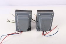
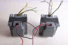
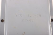
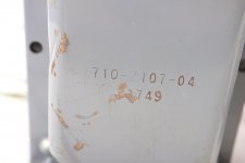
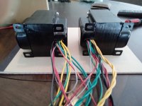
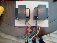
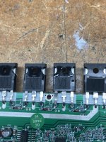
Too many things to photograph all separately and the majority are in as new condition, but I will take photos of anything potential buyers wish to see (particularly the pulls and pics of the rare trannies to show legitimacy as I dont have the original full Toshiba boxes).

Prices are in USD, but if any Aussies want to purchase, i'm happy to just do the straight conversion (not paypal conversion, just pay me the USD price converted at the current market rate).
Most is not large enough to cause too much expense, or trouble with international shipping, so if you will pay it, i'll send it. Happy to accept USD via paypal also if you would rather avoid conversion.

I have tried to price things fairly vs current market rate by searching around and comparing to what I paid if I have records. I have not searched exhaustively for the cheapest new price (not clearance) so if you think something is priced too high and can show me somewhere it is cheaper, do let me know, maybe we can work something out. No comments on absolute value of some of the more esoteric items please, I wont enter into it 🙂 My own views have changed over time, but that doesnt mean I want to give them away (although I will very likely give some stuff away towards the end, maybe for a donation to the forum.

I will entertain deals for multiple purchases, just PM me.

OK, so time is moving along and quite a few (most) of the transistors have sold

Prices marked down again 22/06/22 priced to sell. Marked down and added package prices. Dont hang around for them to go down further. if you have a reasonable offer, make it 🙂
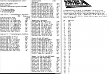
Toshiba NOS JFETS


100 x 2SK170BL = $240USD ONO SOLD Shipped

100 x 2SK170GR = $200USD ONO (PENDING) SOLD Shipped


50 x 2SK246BL = $40USD (PENDING) SOLD Shipped


50 x 2SJ103BL = $40USD (PENDING) SOLD Shipped


2 x 2SJ109V = $80USD $60USD for the 2 (used)


4 pairs of 2SJ74BL @ $20USD ea (think these were from Spencer, but I honestly cant remember. they are marked with values, will dig out for details if anyone is interested) I had the wrong price on these, my apologies.
SOLD Shipped


Semisouth


1 x Pair of R125 Semisouth = $180USD ONO (curve traced, turned out thanks to Patrick I only needed 2) SOLD and shipped
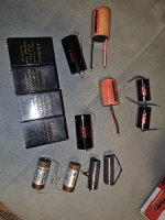
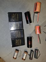
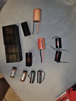


Film Caps


2 x VCAP TFTF 0.22µF/600V $200USD ONO (this is more than 40% off the current clearance pricing. these great caps are not available anymore)


4 x 0.1uf VCAP CuTF $480USD $450USD $350USD ONO (unused.. definitely up for sale now)


4 x 0.22uf Mundorf SIO $150USD $120USD $100/set


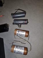
2 x Mundorf mcap 330uf 250v used $50USD $40USD ea


4 x Auricap PP 3.3UF @ $50USD $40USD/set


Will take $600USD for the lot, including the 2 vcap TFTF, which are 1uf IIRC (will unpack and find out, if anyone is genuinely interested)


Electrolytic caps

8 x Mundorf Mlytic 2200uf/63 @ $12.50 = $100USD/set $80USD/set


8 x Mundorf Mlytic 6800uf/63 = $140USD $120 $100 ONO

Will take $150USD for all 16 mundorf electros


Assorted Nichicon 'audio grade' caps. $50USD $40USD for the lot
100µF/25V KZ
100µF/50V KZ
220µF/25V KZ
220µF/50V KZ
470µF/50V KZ
220µF/25V FG

nichicon.jpg


Blackgate
BG NXHiQ, N and standard.


Again I have searched around and priced these not insignificantly lower than what I was able to find and what ive seen in the past. I cant look everywhere though.

10 x Blackgate NX HiQ 47µF/6.3V mostly used. some remains of potting on a couple = $450USD $300USD ONO (will split out, ask for price)
4 x Blackgate NX HiQ 22µF/6.3V mostly used. some remains of potting on a couple = $80 $40USD(10ea) ONO
4 x Blackgate FK 47µF/16V used $100 $75USD(20ea)
3 x Blackgate FK 100µF/25V NOS $40USD each ($100USD for the 3)
4 x Blackgate Standard 47µF/100V used $200 $180USD $150USD(set)
2 x Blackgate NONPOLAR 100/6.3V mostly used. some remains of potting. look fugly, function fine. make me an offer.
4 x Blackgate PK 47µƒ/25V NOS I dont know what to ask for these.


Will take $600USD for all Blackgates

blackgate_pulls.jpg


ELNA Silmic II, assorted values. $40USD the lot
2200/50V
470/50V
220/50V
100/50V
2022-06-11-19-19-34.jpg


alps blue velvet Japan 50k stereo $15USD


DACT CT2-2 50K = $170USD $150USD ONO (lightly used)


ELMA 24 pos 1 layer 04 - 1100 - 20 1107 endless $40USD $30USD ea (2 pieces)


ConneX Socket 7 Pin Miniature CNC Machined *PTFE Chassis Mount Gold Plated 8 pieces = $100USD $80USD


Connex 7 pin ceramic tube socket x 8 = $40USD


Eharmonix 12AU7 x 4 = $70USD $50USD


ETI silver bullets $150USD $80USD set 4 (old style, NOS)


Furutech IEC rhodium FI-09 = $70USD $60USD ONO


Furutech FP-681-2 Gold XLR Panel mount female x 4 = $150USD $140USD $100USD/set


OK thats it for now. i'll go through the more industrial high quality stuff tomorrow to find some stuff to list.
  • Like
Reactions: stretchneck

Simplified F5 as Headphone Amplifier. Easy project.

This idea is based on the F5 Simplified schematic by Nelson Pass.
As it stands it is for 32 Ohm headphones.
The gain is a bit over 2.
Gain can be adjusted by R2 and R7 for other headphones.

Transformer can be 2x12VAC or possibly 2x15VAC.
The bias is here 227mA Class A and this gives a THD like 0.010%.

Attachments

  • Simplified F5 Headphone_01.jpg
    Simplified F5 Headphone_01.jpg
    95.1 KB · Views: 550
  • Like
Reactions: nicoch58

Xover troubleshoot

Concerning my Chartwell LS3/5A's:

I have made a couple clones of these lovely 44 year old speakers, because i love them so much. but my originals have lost the tweeter output. I tested the tweeter and all is good. This particularul 15ohm Xover has a history of one of the resistors getting too hot and indeed, a visual shows some good darkening of the PCB as it rests just on top.
I swapped out the Xovers and all is good so how does one test a Xover without ruining the original from a value perspective? AND, without disconnecting a single leg of any passive component? any secrets?

P.S. I have yet to measure the difference in ohms between both Xovers from outside the cab but i imagine they wont be the same.
Thanks

New Issue Forum thread reply windows getting mashed up, comment and question wrong way round. Something keeps moving this from behind. What is it ??

This new platform format hangs on me.....this message keeps appearing "oop´s We ran into some problem."..as my recent post to 6A3summer got completely mashed up. I get multiply reply windows which is annoying, and it isn´t a sticky keyboard.

Can anyone advise on replacement for a 2SK105H transistor please?

Hey all - I'm wondering if anyone can help me find a replacement to this transistor please. If this isn't the right subforum to post this, please let me know. Thanks!

I'm trying to develop my repair skills, and am doing some repair work on an 80s integrated amp; this transistor has tested faulty, and the service manual says it's a 2SK105H. This is apparently obsolete, can anyone tell me what a modern equivalent would be please? Any help appreciated!!😀


transistor.jpg

Seeking Advice on Home Mixer/Interface/Monitors

Hi all!

After reading this forum and playing a guitar for a few months, I think I know a bit better what I want in terms of simple home studio of sorts. I'm asking for a sanity check and advice. I am looking for an inexpensive and efficient set of equipment - I am not opposed to spending more if it goes anywhere I understand but generally I want to stay lean.

I am mainly playing guitar (strat) by myself or with my daughter on bass (or she plays by herself). We also have an acoustic with a piezo pickup, a son/brother, who occasionally plays electric piano with us, and we will add a mic. All this in a living room.

  • I want to have instruments feeding into some pedals, then a mixer, which goes to the monitors.

  • We want to record/layer too, so it makes sense to have a mixer with a computer interface.
    • But I do not want to be tied to a computer and to have to power it up every time I want to play a couple of chords, so the mixer and monitors should work without the computer too.
    • It would be convenient to also be able to save tracks and layer on the console, without the computer - but perhaps this is too much to ask from an inexpensive mixer: to be a mixer, interface, and а tracker (?) all in one. Or is it?
      .
  • UPDATE: following the suggestions in the thread, I found another candidate. So, currently choosing between A&H ZEDi-10FX ($300) and Behringer XENYX X1204USB ($209).
  • UPDATE 2: I chose in favor of A&H because both people here in the thread and reviewers on amazon raised reliability issues in the Behringer unit.

    ORIGINAL TEXT: I found this mixer, which seems to hit most points: Allen & Heath ZEDi 10FX. It has 2 hi-impedance inputs, two more "mic" inputs, and some additional line/stereo/usb inputs. It is $300 on Amazon - not exactly cheap but acceptable if nothing reasonable is available cheaper. There are some cheaper mixers like PYLE PMXU 83BT but they seem weird: questionable quality and no hi-Z inputs, just regular "mic". But they are twice cheaper.

  • I plan to hook up the monitor output to a SS TPA3116 2.1 board, which I power with 24VDC.

  • I am not sure what to use for the monitors. I have ELAC bookshelf speakers (DB-52), and an ELAC powered subwoofer SUB-1010 but perhaps they are too delicate? This calculation following @Gnobuddy 's explanations suggest that they should be fine but I am not entirely sure.
    • If these are no good, what could cheap alternatives be?
    • There is an option to use the now-famous Logitech Z-623 but this is a separate can of worms. 🙂
      .
  • The computer setup is less important at this point - but I would like to use a Linux-based DAW if possible since this is the only OS I have in the house.
So... asking for advice on the above. Does it make sense? Are there any better candidates for the mixer/interface?

Thanks!

P.S. Oh, yeah, this is the full list of what I have and use now:

UPDATE 3 (2023-09-13):
I've now acquired all I had in mind, huge thanks to the advice in this thread. Here's the full list of what I have (also see pictures):
  • Allen & Heath Zedi-10FX mixer (with USB 4-channel interface)
  • Simple Frontman 10 amplifier, came bundled with the Squier strat
  • Using the guitar amp from the above + old Yamaha 8" subwoofer wired together as a monitor for live jamming at home (short-term, will upgrade)
  • Sonicake bass multipedal, acoustic multipedal, fuzz; Flamma FS06 digital modeling preamp
  • Squier PJ bass, two Squier single-coil strats (hardtail and tremolo), simple acoustic guitar (Johnson)
  • SM57 mic (yet to be tried)
Guitars go into some combination of the pedals -> to the mixer -> guitar amp+Yamaha sub

-------------------------
Related threads:

Attachments

  • PXL_20230909_015826694.jpg
    PXL_20230909_015826694.jpg
    511.2 KB · Views: 80
  • PXL_20230909_015836981.jpg
    PXL_20230909_015836981.jpg
    619.9 KB · Views: 76
  • PXL_20230909_015856360.jpg
    PXL_20230909_015856360.jpg
    489.5 KB · Views: 79
  • PXL_20230909_015905462.jpg
    PXL_20230909_015905462.jpg
    550.4 KB · Views: 79
  • PXL_20230909_015956152.jpg
    PXL_20230909_015956152.jpg
    539.3 KB · Views: 81
  • PXL_20230913_224427604.jpg
    PXL_20230913_224427604.jpg
    467.5 KB · Views: 100
  • PXL_20230909_015810543.jpg
    PXL_20230909_015810543.jpg
    660.7 KB · Views: 79

Tiny Mod of a Hardtail Squier Strat

I wanted to brag about this little thing I've done: I have this inexpensive Squier strat with hardtail bridge and top-mounted strings. I use pretty soft strings (Gilmour GHS), and the bridge saddles buzzed no matter how I tried to adjust them. So I drilled some holes, installed some ferrules, and now the strings are through-body, and nothing buzzes anymore.

It would be completely trivial except I did not have access to a drill press, so I did it all with a handheld power drill. It took some head-scratching to make the holes line up but I am pretty happy with the result.

I knew next to nothing about the electric guitars, so at first I thought I came up with an original idea - to put the strings through! 🙄 (My original plan was to just drill holes under the bridge, not all the way through, just to make room for the string ends, unscrew the bridge, thread the strings, and put the bridge back - that of course would make it a PITA to change the strings). But quick googling revealed that there is nothing new under the Sun.

The shiny coat does not lend itself to taking clear pictures very well but you can sort of see.

Attachments

  • PXL_20230913_200854101.jpg
    PXL_20230913_200854101.jpg
    488.3 KB · Views: 110
  • PXL_20230913_201132587.jpg
    PXL_20230913_201132587.jpg
    321.3 KB · Views: 111
  • PXL_20230913_201149517.jpg
    PXL_20230913_201149517.jpg
    572.3 KB · Views: 116

Output BJTs for buffer

Gents, let's discuss the linearity of output transistors, mainly bjt, for power buffer.
Background: I built many amps, and sure can be very happy with quite a few, but recently started experimenting with just buffers. Why? I do not need much power, i have plenty of preamps, and buffers sound much better to me after all.
Maybe its a lack of global negative feedback or something else.
Not interested in starting any flame war about putting shades on mona lisa, creating effect box, or insulting the artist. Fed up with that kind of bs.

I created two fully finished buffers based on c5200/a1943, one based on one output pair, one on three output pairs.
Now i want to experiment with other power bjt for outputs.
I got c3263/a1294.
I got w1302/w3281.
I got w0281/w0302. (I typed it incorrectly)
I hope i typed it correctly. (turns out I did not)
Which of these would be most suitable/linear?

https://www.diyaudio.com/community/threads/direction-of-diodes-in-an-amplifier.379908/page-3

Newbie here! - Need help with Tannoy bass driver

Hi all!

Although I'm a long time lurker around the forum, I'm still a newbie and don't have the knowledge to actually provide helpful inputs to anyone...
Still the forum has already helped me find valuable information in various subjects.

This time I'm looking for advise with a problem I have with the bass driver of a Tannoy Mercury m2 speaker

What happens is that the driver stutters intermittently, as if the connection is interrupted.
I've already resoldered the wires that go to the terminals, to no avail...

Is there anything else I can check, or is the driver blown?

Thanks in advance for your help!

Cheers!

What subwoofer is this?

I saw an interestingly built subwoofer and I'm wondering if it's a design that's familiar to anyone. It measures 17" tall, 12" wide, and 4" deep with no visible driver. There are 3 ports on the narrow 4" side and one port on the back under the plate amp. The amp looks like a Rythmik Audio A370-SE. Photos attached

Attachments

  • 1.jpg
    1.jpg
    153.7 KB · Views: 133
  • 2.jpg
    2.jpg
    266.1 KB · Views: 141
  • 3.jpg
    3.jpg
    182.5 KB · Views: 113
  • 4.jpg
    4.jpg
    191.5 KB · Views: 100
  • 5.jpg
    5.jpg
    123.2 KB · Views: 127

Inverse mounting a woofer - I never see this

I’m doing research for a possible build but there is no information on this outside of subwoofer use. I’m wondering why no one inverts one of two woofers in their 3way speaker? I’ll attach a rough sketch.

I can see a huge potential drawback being mechanical noise. The only quiet woofer I’ve used is the Acoustic Elegance TD15h.

Another drawback in this drawing is the bottom woofer is not time aligned, although that may be a nonissue in a 3.5 way design?

Is the reduced 2nd harmonic distortion worth it if mechanical noise can be overcome?
09C4BA50-9FE7-4690-AF02-FF6490FEF2DC.jpeg

DC protection for speaker

Hello all,

I know that is it surely a common title of topic, but I'm working on my new amplifier, and I want to add a DC protection on the output.
I want to manage the output relay with an ESP32 (all function are managed by him). So, "out" will be link to the ESP32.
I seen a schematic from Elektor (July 2012, page 62) interesting, and I simulated on Spice :

schematic.jpg


spice.jpg


All seems work fine, but I want to ask to the diyaudio Engineer here for know if something seems wrong or not 🙂

Thx in advance !

Peerless DT10HFC tweeters X 2

Not a matched as such but identical other than in their looks ( one has tape over the contacts and the other doesn’t)
£50 + p&p

Sold

Attachments

  • 6680BA72-437C-4587-A3DC-2D6BA677913F.jpeg
    6680BA72-437C-4587-A3DC-2D6BA677913F.jpeg
    331.4 KB · Views: 217
  • C9BDFD65-CAD6-4217-BE1A-569214A6D911.jpeg
    C9BDFD65-CAD6-4217-BE1A-569214A6D911.jpeg
    403.9 KB · Views: 178
  • D61352BE-5A82-4D45-B80B-28879E4A102D.jpeg
    D61352BE-5A82-4D45-B80B-28879E4A102D.jpeg
    414.6 KB · Views: 167
  • 580E3F72-995E-4709-AD03-8CB5ED6241F8.jpeg
    580E3F72-995E-4709-AD03-8CB5ED6241F8.jpeg
    399.4 KB · Views: 186

"Schade" feedback and triode connection

Just a quick impulsive question:
I've had very good results using local "Schade" (plate to plate) feedback in (SE and PP) amps with pentode drivers and pentode output tubes.
I ordered some output pentodes with very nice triode connection curves.
Now I'm wondering if triode connected outputs would work as well as pentode connection in this configuration.
Of course I will try it, but they aren't even paid yet, so that's for later. Meanwhile someone might have experience or an opinion.

Cheers!

Speakers have a lot of cabinet resonance

What will you do when you find your recently successfully built DIY speakers have a lot of cabinet talk (cabinet resonance) in spite of the fact that you have already applied a lot of bracing?

Could it be compensated by tweaking the crossover network? Let’s say if you heard a cabinet talk, then you suddenly measured FR and found peaks at some region, e.g., 400 Hz. Can the problem be fixed by introducing a gap in that crossover region, e.g., about 300–500 Hz?

Or are there any more proper or correct methods of eliminating the cabinet resonance?
Projects by fanatics, for fanatics
Get answers and advice for everyone wanting to learn the art of audio.
Join the Community
507,788
Members
7,888,582
Messages

Filter

Forum Statistics

Threads
406,245
Messages
7,888,582
Members
507,788
Latest member
ShepCasey