Denon Turntable Intermittent Issue

I'm working on a Denon DP-37F that's exhibiting a strange intermittent issue: Sometimes it spins forward and the speed locks to the quartz reference, and then other times it will only spin slowly backwards (CCW). All of the power supply voltages check out when the table is misbehaving. I've gone over the boards several times looking for bad solder joints and touched up several. I've tried prodding areas of the boards with an insulated stick and applying heat to either induce or abate the issue. I've also replaced all of the electrolytics around the arm and motor control IC's.

My understanding is that the slow backwards spinning is the motor getting a signal to brake. According to the datasheet for the motor controller IC, which is a TC9142P, the reverse signal for braking is output from pin 9, however that pin is unused in the DP-37F application. Understanding how braking is accomplished might help me narrow down where to focus my troubleshooting efforts. Or if anyone has other thoughts, I'm all ears. @Mooly 🙂

Schematic.jpg

TDA2030A dual supply heat sink isolation

Hello!
I have bought a 2.1 Chinese system which i was planning to modify originally. So, i knew what i was buying. It sound good for me, but there is a problem with humming and hissing.

Humming and hissing is present constantly and is not dependent on volume level. Humming from sub was 150Hz

So, i replaced the cheap transformer (which was "singing") with toroidal transformer, added 4700 caps and it helped a lot. Now sub is humming only 50 Hz and very very liitle. Good enough for me.

However, side speakers are still hissing and humming at too high level for me.

I checked the circuit further.

It uses TDA2030A and dual supply with central point from transformer. There is no real ground anywhere (only L+N from socket). I have read the datasheet and it said that metal plate of TDA2030A is connected to V- and must be isolated from heat sink when using dual voltage supply. I checked and there is not isolation between metal plate of TDA2030A and the heat sink.

Then i figured that when i touch the heat sink with my finger the 50HZ humming because a lot less.

Is my following understanding correct:
1) The heat sink works like antenna and all the noise it collected goes to V- creating extra 50HZ humming
2) Heat sink must be isolated and grounded
3) I need to bring ground from socket and connected it to central point from transformer (common wire)

If so, then how do i mount tda2030A isolated from heat sink? I need to use a screw, and screw thread will touch the metal inside TDA hole and the hole inside the heat sink. Need some kind of plastic screw?

On the attached picture:
1) blue dots - input from transformer (- and +)
2) greeen dot - central point from transformer
3) red does - output from rectifier bridge

Attachments

  • IMG_20231122_214819.jpg
    IMG_20231122_214819.jpg
    251.4 KB · Views: 185
  • IMG_20231122_214851.jpg
    IMG_20231122_214851.jpg
    242.5 KB · Views: 141
  • IMG_20231126_095233.jpg
    IMG_20231126_095233.jpg
    198.9 KB · Views: 134

AK7738 - need help extracting I2S output

Hey all,

I have a source unit that uses an AK7738 IC and I would like to get the I2S signal straight from it using an 'I2S to SPDIF" converter board. I noticed the converter has the following inputs:
3 pin -----> MCLK master clock input
4 pin ----->LRCK clock input
5 pin -----> BCLK bit clock input
6 pin -----> SDATA data input

Im trying to fully understand the datasheet of the AK7738, and noticed it has several SDATA, BCLK, LRCK pins (SDATA1, 2, 3.. BLCK1, 2, 3..etc) and one MCLK pin so figure Ill stick to the #1 set first.
MCLK.JPG

Set1.JPG


But now i noticed pins 20/21 are dual function and i dont know exactly to set them to output according to the tables below:
InternatPDpins.JPG

PDpins status.JPG


Im guessing at power-down (unit turned off?) both LRCK1 & BICK1 are set to input but when the unit's on is set to output? And SDOUT1 is output when unit's off but input when the unit's on?

* How can I make them all output when the unit's powered on? (guessing somehow set LRCK1 & BICK1 to H and maintain SDOUT1 to L)

Goal?
Its an Android head unit and would like to bypass the operating system and thus bypass Android's limitations

Tangen Class A

Ive just got this great amlifier "Tangen Class A No5" does anybody know anything about it? The owner past away, and the relatives didnt know anything about it. So if anybody has some info, thanks a lot. What I see is 8 pcs 40V 60000uf capasistors and a huge trafo. I allso got the speakers "Tangen Monitor 8R" its 2 way bulit in a huge cabinet 1130mm tall x 680mm deep x 280mm wide approx 100kg, there is no info on these either, so if somebody know something- I will be gratefull. What I can tell, they sound amazing together with the amp!

The Truth and Fairy Tales of S\NR in Phono preamps (with multilanguage subtitles)

The Truth and Fairy Tales of S\NR in Phono preamps (with multilanguage subtitles)
or
9 dB of deception from the the "input shorted" on FETs and 14 dB of fraud from the "input shorted" on bipolar
s

Nick Sukhov masterclass on Cy-XXI/TEAC PE-505/TEAC PA-B10/Accuphase C47/iFi ZENAirPhono/X-Altra/The Grail SE+

Login to view embedded media
Full version with circuit diagrams and info files is here! [ https://www.patreon.com/posts/9-db-obmana-ot-i-90332386 ]

more about "noise input shorted" https://www.patreon.com/posts/68014370
more about highest quality phono preamps https://www.patreon.com/posts/73044002

Attachments

  • JLCPCBorder_phono_v7.jpg
    JLCPCBorder_phono_v7.jpg
    248.1 KB · Views: 141
  • фонокоректор Су-XXI v.7 монтаж у подвалі тонарму крок 1.jpg
    фонокоректор Су-XXI v.7 монтаж у подвалі тонарму крок 1.jpg
    249.6 KB · Views: 131
  • фонокоректор Су-XXI v.7 монтаж у подвалі тонарму крок 2.jpg
    фонокоректор Су-XXI v.7 монтаж у подвалі тонарму крок 2.jpg
    222.5 KB · Views: 122
  • Cy-XXI_depo196.jpg
    Cy-XXI_depo196.jpg
    200.5 KB · Views: 133

Adding a Linear PSU for Sony X800M2

Here is what I would like to do: https://www.diyaudio.com/community/threads/sony-ubp-x800-psu-tweak.381585/#post-7518240

If I bought an external PSU like this the one below would I need to add a choke?

Is it necessary to add the ground to the mb?

Can't I just buy the psu below and hook it up directly to the player without choke and ground to mb?

Any other way to wire this that would be better in your opinion?

Tried asking in the above thread, but was without luck.
I'm a noob so any help at all is appreciated! Thank you!

Attachments

  • Screenshot_20231128-071402.png
    Screenshot_20231128-071402.png
    285.3 KB · Views: 90

split power supply from two single PSUs

Hello. I have a question:
Is it possible to get split power supply by connecting two single switching power supplies as shown in the picture? And what will happen if they have slightly different voltages (+- 0.1-0.2V)? Power is required for the tda2050 amps and active filters based on the op-amps.

I am aware that it is better to use a transformer for such a project, but for a number of reasons this is not possible.

Attachments

  • Clipboard.png
    Clipboard.png
    2.5 KB · Views: 83

LCD Display for Input Selection on Tube Amp

Hello all! I’ve been a lurker on here for some time but have finally committed to my DIY set up. One feature I wanted paired with my pre amp was an input selector which had a digital LCD layout. I’ve seen Teensy and Arduino mentioned on this forum but I’m not looking for any other data to be displayed outside of which I put in selecting along with a controller to switch between them. Has anyone successfully done this? For an idea of what I’m talking about if you look at a Nagra Classic Pre-Amp there’s a controller with a LCD display for the input selection. I plan on having a separate knob for my volume. Thank you in advance for the help!

Technics SL-PG440A

I'm looking at refreshing my Technics sl-pg440a, with sensible simple upgrades. I will be replacing the opamp to the opa1642 on a soic8 to dip adaptor, capacitor wise, where should I be looking to put oscons, panasonic fc's etc? Please see service manual attached

Attachments

The Well Tempered Driscoll Clock plus Freq. doublers 5.6mhz to 22mhz

Amazing clock ready to roll. long and short cable options included. no diy on the boards andrea built them and I did the enclosures. I am thinking $350 plus shipping? I am also open to trades. If you would like to talk to designer he is still active at the well audio.com No power supply included. I used a barrel jack splitter and a 15v ps. Thanks!!!
1701327309248.jpeg
1701327322575.jpeg

Help! Trying to get a meter working putting a new project into an old Harman Kardon tape deck...

I'm hoping I finally found the right people to help me tackle this project. I am Currently building a Raspberry Pi/DigiAmp+/Volumio based system with touchscreen into an old Harmon Kardon CD101 tape deck. I replaced the Tape section with the touchscreen and the rest of the system is essentially gutted. The large input level knob has a new rotary encoder behind it for tactile hardware inputs rather than just touchscreen controls. I will utilize other buttons and encoders just to make use of and integrate as much of the face plate as possible. I am going as far as removing some labels and making decals that match the design when a function has been repurposed.

One function that was #1 on my list to repurpose was the level meter in the faceplate. This particular model has a little standalone circuit board running LCD display (Level Meter) The meter is connected to the little board via a small a harness and the little board is connected to the main deck through a ribbon cable. I didn't need to figure out wire usage from small board to LCD as both units were retained and plug into each other and only each other.

I had to figure out what the 6 wires (5 in a ribbon +1 standalone) were. I'm the type of person who will learn anything to achieve a goal but electronics give me a run for my money. Especially when it comes to reading diagrams and calculations and that kind of stuff.


I have figured out this boards 5 wires going in are +VCC which is 12.7, Then V-, Then Ground, Then 2 audio signals, and the standalone wire was the hardest to figure out but I believe its another +Vcc (The standalone wire is the one at the bottom of the LCD picture below traced in blue) Through metering different things and reading component numbers I figured out which wire is which in this 5 cable ribbon.

HK Level Display.jpg


This image below is the two signal lines going into the board.


HK Line Amp.jpg

This last image is the blue standalone wire that goes to a few capacitors and such then the power supply.


HK Blue Line.jpg


I hooked it all up and it doesn't work.

My only idea is one thing I questioned all along.... I don't know what kind of audio signal this is running off of. Its internal in a tape deck from a bookshelf system so it is not amplified. It also appears to cut in with the headphone jacks so I figured it was some type of analog basic R+ and L+. For testing purposes I hooked it up to my amplified speaker positives but had the volume down almost to zero.

NOTHING! I am hoping you guys can look at these pictures from the service manual and help me figure out what kind of signal I need to get this meter working. I would like to stay with the original HK meters instead of something more modern just for aesthetic reasons.

I am at work right now and cannot test things but I did have the idea come across my mind today that when I did these tests I did NOT have speakers plugged in and that may be why the meters didn't work, with no load on the amplifier, no current coming through the wires? This troubleshooting shows my weakness in this project.

If you guys could give me any pointers to getting these control board the signal it needs that would be awesome.

One last point of information is, yes, I know the LCD's DO work. In some of my troubleshooting when I was plugging the LCD harness in it was on an angle so not all pins were making contact and the LCD would light up constant to full meter.

No magic smoke has been let out and all components looks to be in good operation condition, I'm confident with the right "Signal" this should work.

Thoughts on SET Direct Driving the Stator in a Diaphragm Stator Diaphragm sandwich ?

I recently started reading about ESL’s, mostly out of curiosity with no immediate plans to build anything so dangerous as proposed. However, I do have a few 833a triodes and I got to wondering how I might one day use them; SE would be preferable due to limited supply and power demands.

Looking through TubeCad/John Broskie’s blog in posts 179 and 400 a couple of his sketches looked interesting. Also the electrical segmentation principle of the wire stator referred to on Jazzman/Charlie’s blog looks well worth implementing. I’ve downloaded Steve’s excel sheet.

I’ve not yet seen any real life working examples where a single Stator drives two diaphragm’s which leaves me wondering if there is something wrong/flawed with that approach. I would imagine it to be cheaper and quicker to make than two having two stators/one diaphragm. In blog post 400 John say’s “In both examples, the two diaphragms move in phase, which means that effectively we have two single-ended diaphragms working in tandem, so the distortion inherent in single-ended operation cancels as it does in a regular push-pull electrostatic loudspeaker.”

I guess having the Licron Crystal spray on the outer side of the diaphragms might reduce the risk of shorts.

I was also wondering whether a gyrator load on the tube and source follower might work well (better than a choke) in this application driving the capacitive load of an ESL; Mosfets with up to 4.7kV are available.

https://www.tubecad.com/2010/01/blog0179.htm
https://www.tubecad.com/2017/10/blog0400.htm

In the tube circuit shown John has the tube driving the diaphragm, but I was thinking of inverting them, i.e. tube driving segmented stator between diaphragms.

I suppose for safety a coupling cap could be added to block the deadly Tube HT supplementing in a low current dc bias on the stator.

I was unsure whether to put this here or in the Tube/Valve form.

Edit - Stopping the wire stator flexing might be difficult, Perhaps the stator could wound over/either side of a central brace.

Attachments

  • SET ESL gyrator load.PNG
    SET ESL gyrator load.PNG
    9.7 KB · Views: 78
  • SET ESL gyrator load2.PNG
    SET ESL gyrator load2.PNG
    18.6 KB · Views: 82

Please talk me into/out of building Linkwitz LXmini

Hi.

By no means am I an audiophile or understand more than a bare minimum about HIFI gear, but it happened so that at some point I was a bit bored and built Paul Carmody's Overnight Sensations and later - Amigas. OS have found their place in the garage, whereas the Amigas are in the living room and are mostly used for movies. I never had a proper amp/HIFI setup as back then I couldn't afford anything fancy, so decided to build an amp and did it with an ICE125ASX2 module (ebay) in a metal box and a volume dial. The amp is connected to a small SMSL bluetooth receiver as my TV, annoyingly only outputs either optical or bluetooth..and I really didn't want to have extra remotes. I would normally watch stuff on the TV from an Nvidia Shield.


Now..I think I might be getting to the bored stage again and I might even afford to DIY the Linkwitz LXmini as a) I like the looks b) I have a lot of respect to S. Linkwitz as one of the very well known speakerbuilders.
Could you perhaps help me decide if LXmini is the right thing for me and if it is, how to make it convenient and family friendly (=as few remotes for different devices as possible) as ownership of the aforementioned will need to pass the Wife Approval Committee (WAC).

1) The room they'd be used in is approx 4.5m x 3m, so not too big. They'd have to be pretty close to the front wall. Is that a problem ?
2) As I understand I need miniDSP to go with them. Are there alternatives?
3) Would having a AV receiver instead of an amp solve the problem of a) needing an amp b) wanting as few remotes as possible?

I do have access to 3dprinter and a small DIY cnc, so building wouldn't be a problem, but I'm trying to work out if the investment itself is worth it.

Thanks for any and every comment.

RF

Almarro A318 volume pot help

I'm trying to help a friend who removed the 250k alps pot from his Almarro a318b and attempted to replace it with a 100k tkd pot before realizing he was in over his head. Now I'm in over mine. Unfortunately there are no pictures of the pot before it was removed. I tried wiring the input to pin 1 L&R and the output to pin2 L&R, with the ground from the source selector switch on pin 3 R and the ground from the output side on pin 3 L. All I get is a loud distorted buzz from the speakers. The signal wires also have shields that look like they were soldered somewhere on the original pot, I tried coupling them with their respective ground wires and it made no difference, both shields are floating on the ends not connected to the pot. Any help is appreciated even just a picture clearly showing the stock wiring. I know there were originally some DC blocking caps on the input, but those were discarded before I got the amp. Here's what I have without the ground wires soldered in. The red wire on pin 2 broke while I was pulling it out for a photo, but there's enough slack to reconnect.
PXL_20231007_184917416.jpg

For Sale Pro-Ject Pre Box S2 DAC/Preamp

For Sale: Pro-Ject Pre Box S2 DAC/Preamp. Dual ES9038Q2M Chips.

The tiny 5v USB power connector broke off, so I just used the other USB connection for power. You can power the unit via USB (Type B connector) and switch to Optical or Coax, or connect direct to computer for USB connection.

Comes with the Type B USB Power adapter and cable. I have a non-stock, programmed universal remote included.

Currently sells for $499 on crutchfield...hows $150 shipped CONUS?

Product highlights:​

  • dual mono circuitry with two high-performance ESS Sabre DACs (ESS9038Q2M)
  • high-res audio playback, including PCM-based files up to 32-bit/768kHz and DSD512
  • full hardware-based MQA support
  • selectable digital filters
  • vanishingly low jitter (as low as 100 Femtoseconds)

Specs:​

  • frequency response: 20-20,000 Hz
  • total harmonic distortion: 0.0003%
  • headphone output power: 68 mW (32 ohms)

Inputs:​

  • 1 coaxial digital
  • 1 optical digital (Toslink)
  • 1 USB Type-B for connection to a computer

Outputs:​

  • RCA stereo output (rear-panel)
  • 1 front-panel 1/4" full-sized headphone output

Attachments

  • PXL_20231113_210142080.jpg
    PXL_20231113_210142080.jpg
    141.6 KB · Views: 116
  • PXL_20231113_210147919.jpg
    PXL_20231113_210147919.jpg
    139.1 KB · Views: 115
  • PXL_20231113_210155575.jpg
    PXL_20231113_210155575.jpg
    142.8 KB · Views: 112
  • PXL_20231113_210200623.jpg
    PXL_20231113_210200623.jpg
    210.5 KB · Views: 110

Sharp CD-C612 Restoration Advice

I recently found an old sharp / Sony CD-C612 3-disc CD changer at a garage sale for $15. I took it apart, cleaned out the laser lens several times, and used a can of compressed gas to attempt to clean the dust out of the circuit boards (there was alot) I bought an RCA to 3.5 mm adapter to plug it into my computer, so I could have surround sound coming from my computer when watching movies. All that ended up working great with the exception of cleaning the laser lens. I used a CD lens cleaner from Best Buy as well as rubbing alcohol on a Qtip - multiple times. I'm starting to suspect it is not the lens that is the problem. While CDs play much better than they previously did before cleaning, they still tend to skip periodically. I even bought a bunch of brand-new CDs to ensure it wasn't on the CD end. Brand-new CDs will still periodically skip. Not very badly, but still enough that I can't generally get through a full CD without some intermittent skipping.

I'm wondering if anyone has any suggestions on what else I can do to fix this so it doesn't skip at all.

Also, the unit did not come with a remote control and I am trying to find one on Amazon but finding a remote for the exact model seems impossible. I would greatly appreciate it if anyone could point me in the right direction as far as a suitable remote control that would work for this unit because I'm really not sure which remote controls would work for it.

Qts when signal freq is >2Fs, does it change something?

Hi!
I read in some thread that a high Qts was better at high frequency (imagine Fs has been properly filtered thru HP). The (brief) explanation seemed to be related to what is seen in force transmisibility plot, or more clearly, in displacement transmisibility plots.

1701069407260.png

The transmisibility of displacement from damper to mass (I guess surround and spider back to cone) is proportional to damping ratio. Does this means an improvement in surround cone reflections? if such, which are the audible effects of that?

Looking for a competent re-coner to replace rubber surround on Usher 7" Carbon Woofer 8945A

Need help to replace a rubber surround on this woofer and need help from someone who knows where to source needed parts/rubber surrounds. Usher 7" 8945A were popular and some say they were a clone of Scan Speak Carbon 7" woofers.

Attachments

  • IMG_8053.jpg
    IMG_8053.jpg
    801.5 KB · Views: 155
  • IMG_8051.jpg
    IMG_8051.jpg
    562.1 KB · Views: 104
  • IMG_8052.jpg
    IMG_8052.jpg
    682.2 KB · Views: 100

Which 2 of these 4 to Keep?

I need to get rid of 2 out of 4 subwoofers that I currently have. These are mostly for HT 90% and music 10%. I think I already know the answer but just wanted to see if anybody else has something to change my mind.

*Episode ES-SUB-CUB8-110
*Velodyne Impact Mini
*Proficient S8
*Klipsch KSW-10

All of these are part of used equipment buys from the past. I currently have the Episode and Velodyne hooked up and I think they do quite well together, deeper extension than expected and nice clarity and accuracy. I have never listened to the Proficient or Klipsch. A quick look online seems to indicate the Episode and Velodyne are of much better quality, and used prices they seem to fetch a higher price than the other two. So at this point, I'm thinking just sell the Klipsch and Proficient.
Anybody with opinions on this?
Thanks

2 way "TAD-inspired" / "Beyond the Ariel-type" medium-high efficiency system

Hi all,

just a quick - and long overdue - post to briefly illustrate the latest incarnation of my own home system.

As the title of the thread suggests, this is essentially a "classic" two way "large format monitor" speaker, comprising a 15" Woofer and a large-format compression driver mounted to a horn.

A few key points:

- THE WOOFER is NOT a typical modern PA-style 15-incher (high Mms, ultra-high BL, very low Qes, lowish Qms, highish Fs), NOR is it a "vintage" component (Altec, etc.).
Instead, it is a Fostex FW405N, which is a RARE example of a modern, recently designed (albeit now discontinued) 15" woofer with some key "old school" characteristics (medium Mms, medium BL, medium Qes, high Qms, low Fs).
This, IMHO, stikes the "goldilocks" compromise between efficiency, low-level-detail retreival, "musicality" and linearity.

- THE COMPRESSION DRIVER is NOT a typical modern PA-style unit (rapid-flare exit, high Fs, often Titanium, or sometimes polymer diaphragm).
Instead, it is a 1990's JBL 2450 (2" exit version), retrofitted with a Truextent Beryllium diaphragm.
This, IMHO, strikes the "goldilocks" compromise between headroom (100mm diaphragm), low-level retreival and lack of resonances (Be), and ability to "load" down to mid-low frequencies (slow-flare exit)

- THE HORN is NOT a typical modern PA-style "constant directivity" waveguide (rapid-flare expansion, poor low-frequency loading, sometimes nasty diffraction slots in the older designs...), NOR is it a "vintage" component (e.g., Altec multi-cells or classic "sectoral" horns a-la 511, etc.).
Instead, it is a Yamamoto SS-300, which is a sophisticated evolution of a classically-derived hypex radial horn, but with a smooth profile devoid of any sharp corners, any discontinuities or diffraction-inducing steps along its expansion, and a smooth round-elliptical throat adaptor whose expansion parameters are perfectly matched to those of the JBL 2450 driver used. It is also carved out of a solid block of Japanese cherry wood, thereby killing virtually all internal resonances. Its "raw" frequency response is very smooth and extended from approx. 300Hz to over 15kHz (-6dB), with useful output to 20kHz. A mild "hump" centred around 2kHz is taken care of by means of a passive parallel-RLC trap.

- THE CROSSOVER is ACTIVE, but NOT DSP-based, NOR any standard off-the-shelf "pro" unit.
Instead, it is a bespoke Marchand unit, with asymmetrical low-pass and high-pass slopes individually tailored to the Woofer and Driver+Horn responses, and aiming to obtain the best possible phase-match between the two unit's outputs over a wide frequency range centred on the crossover frequency, which - incidentally - is a LOW 500Hz. For those who are interested, the topology is similar to that adopted by TAD in their glorious 2401, 2402 and 2404 monitors (i.e., 6th order low pass and 2nd order high-pass electrical slopes).

The whole system is driven by a mid-2000s Esoteric multi-bit DAC/Preamp > Marchand active crossover > Yamaha class AB amp (woofers) / Accuphase class A amp (drivers).

A few pictures to illustrate the finished product below.

Cheers!
Marco

IMGP2373_resize.jpg


One speaker.jpg

Seeking Advice on Amplification for Linn Isobarik DMS Speakers

Oczywiście, oto przykładowy post na to forum:


Title: Seeking Advice on Amplification for Linn Isobarik DMS Speakers

Hello fellow Linn Isobarik DMS enthusiasts,

I recently scored a pair of Linn Isobarik DMS speakers at an auction and I'm eager to fine-tune my setup for the best possible audio experience. I currently have two Linn LK140 amplifiers in my arsenal and would greatly appreciate your insights on the best way to integrate them with these speakers.

Current Setup:

  • Linn Isobarik DMS speakers
  • Two Linn LK140 amplifiers
Questions/Assistance Needed: I'm torn between using a single Linn LK140 amplifier for both speakers or upgrading to a bi-amp configuration through a crossover. I'm reaching out to the community for opinions and advice on the following:

  1. Single Amp vs. Bi-Amp Configuration: Do you think one Linn LK140 amplifier is sufficient for the Linn Isobarik DMS, or would a bi-amp setup through a crossover yield noticeable improvements?
  2. Crossover Recommendations: If bi-amping is recommended, any suggestions on a suitable crossover for the Linn Isobarik DMS?
  3. Alternative Configurations: Are there other creative ways to connect my two Linn LK140 amplifiers to these speakers that I might not have considered?
I value your expertise and any advice you can provide. Thank you in advance for helping me optimize my Linn Isobarik DMS setup!

Best regards,
Bartosz

Attachments

  • mój linn 1.png
    mój linn 1.png
    529.1 KB · Views: 263
  • mój lin 2.jpg
    mój lin 2.jpg
    172.5 KB · Views: 167
  • mój linn 2.jpg
    mój linn 2.jpg
    187.9 KB · Views: 151

How to reattach tweeter protective grill cover?

The protective tweeter grill covers in a pair of my Acoustic Energy AE1s have fallen off. The tweeter itself is fine.

How do I reattach them?

I really do not want to affect the speaker at all.

Hot glue? Epoxy?

Do I attach the goo to the cover first and then settle it on the tweeter? Or otherwise?

I assume the crossover was designed to take the acoustic effects of the protective grills? I did listen to the speakers briefly and they didn't sound untoward but I would like to keep them in their original form ( I did replace the foam surrounds with factory sourced butyl replacements ).

Thanks

Attachments

  • 20231118_123642.jpg
    20231118_123642.jpg
    276.4 KB · Views: 80

Heybrook HB1 Mk1

Hi,
I've owned a pair of Mk1 HB1s since new (1984-5 ish). I've re-foamed the bass units due to rot and replaced the tweeters. My last job is to re-cap the crossovers. I attach a couple of pix of the actual crossover and a schematic. Looks very basic. Question are all the plastic box type components capacitors? I ask because the info on cases is very limited. I guess the two in parallel are to give a total value 2.7mF that is not standard. The 4.7 across the LF unit is actually marked 4.7k 100. I assume this is 4.7 mF 100volt wkg.
Can't find good info on HB1 anywhere despite the fact they seem to be well thought of. They are my only speakers!!!

Attachments

  • photo(1).JPG
    photo(1).JPG
    524.1 KB · Views: 1,538
  • heybrook-H1B-Mk1-XO 2.JPG
    heybrook-H1B-Mk1-XO 2.JPG
    150.8 KB · Views: 457

Bruel & Kjaer 2204 major noise issue

Hello all,

I have a Bruel and Kjaer 2204 that I repaired. When I first purchased the unit, it had a nasty bleed-in (~2.5kHz, same as the voltage generator) coming from what I can only suspect to be one of the output amps. Replacing all of the polarized caps unfortunately did not fix the issue. I disconnected the REF signal wire to make sure it was not causing the noise. No change was seen.

Adjusting the output attenuator quickly leads to a gain in the noise, thus why I suspect that it is coming from the amplifier.

The input attenuator dial does not change the noise's amplitude. The noise is the same as the noise produced by the transformer and the power signals prior to rectification to DC.

Please, your advice on the matter is appreciated.

Respectfully,

Crossover point and directivity - how important is it? And what is the impact of material mistmatch?

I was watching this earlier: Galion TS Voyager
I'm not normally one for LS3/5A type speakers - especially at the prices asked these days - but I thought this was interesting.
Not least - a fully labelled XSim with the drivers and crossover components.
The designer is clearly no idiot, and identifies why he's crossed rather high.
But that must result in a directivity mismatch and like many I suspect I'd have gone for an LR at 2.5-3k.
Any thoughts? Is it contributing to the sound signature described?
I'd have guessed one of the pricier Monacor drivers, but refreshing that its so inexpensive at Dayton, and so few crossover parts. And interesting that he didn't go for a 19mm tweeter.

Visor

Did some searching on the forum prior to posting this topic, and came up empty... and perhaps that's because this is an obvious-as-hell topic that I'm just late to the table with...

In 2022 I purchased a Carson Pro Series MagniVisor Head-Worn LED Lighted Magnifier. I'm 57 and my eyes are not what they used to be, despite readers in several magnifications laying about the place.

But when it comes to working with reeeeely small stuff (inspecting tweeter wire-coils / observing just how much ferrofluid is filling the VC gap for instance) and needing to discern incredible detail, a headlamp-magnified visor is one of the handiest tools in the shop! They are available all over online stores: I picked one up off Amazon for about $75 ~ which got me a decent one ~ they come in all shapes and sizes; mine has a kit of four different magnifying lenses and a micor-petzl style headlamp. The strongest / thickest lens offers incredible detail!

A.

Attachments

  • Visor.jpg
    Visor.jpg
    83.9 KB · Views: 90
  • Like
Reactions: vinylkid58

Cracked Sound!!

Hello, My tweeter and mid-range distortion sound like a speaker cone that has cracked. That happens when the vocals or bass are loud. The high frequencies is dominating the amplifier. Should I change the C7 100pf to 47/22pf? by the way I don't have pre-amp I'm using TDA7439 audio processor. but I have also tried with direct audio input to amplifier, still got cracker sound. but it produce more crack sound when it goes by the audio processor because it enhance more.

Thanks.

Attachments

  • Final_Diagram.png
    Final_Diagram.png
    58.2 KB · Views: 158
  • DSC_0048.JPG
    DSC_0048.JPG
    121.6 KB · Views: 155

For Sale Sonore OpticalRendu Music Player

Sonore OpticalRendu Music Player with 7vDC LPS linear power supply, Optical cable, media converter and switching power supply.
Comes with both ends of the digital SFP Fiber Transceiver and a RJ45 if you want to bypass the digital and just feed the Rendu with an Ethernet cable.
Read all about it here: (Although I'm selling the earlier version, it looks the same.)
https://www.sonore.us/opticalRendu.html New retail is $1600 for Rendu only.

Asking $800 for the whole kit and kaboodle. SOLD!
OpticalRendu; ($1295)
LPS lenear power supply, Optical cable, media converter and switching power supply came with the package (Black Friday Deal 11/24/2020)
IMG_5972.jpg
IMG_5971.jpg
IMG_5970.jpg

Should I fix or Should it go now?

Hello someone got us a yamaha A-S801 amp for a wedding gift !!!!
I am a musician but dont know much about HIFI...
also someone just gave me a pair of old AR48s in really rough condition... for sure the foam needs to be change and the paper cone looks weird too.
what options should I go with considering i have a really good amp but we want good/?vintage? looking speakers. The Acoustic in the living is bad... echo... should I might try to make it better with those stuffs you put on the walls? that doesnt just look like foam?

1# replace foam and(or not) the paper cone
2# replace the whole woofers to put better quality ones? and if that please give me recommandations.
3# get a new set of vintage speakers? should I get a subwoofer too?
thank you very much !

Attachments

  • 368354788_892085378784991_5764233324773415946_n.jpg
    368354788_892085378784991_5764233324773415946_n.jpg
    89.7 KB · Views: 118

Best transformerless method of converting balanced to SE

I'm building myself a little mixer/headphone driver box for my guitar pedalboard. Among other things, it accepts a balanced line input, which I convert to SE cheaply and, apparently, ineffectively, as I'm getting a good amount of buzz. (from this input only, everything else is quiet and sounds great)

For this input, I'm using a 1/4" TRS jack, and I do have a ground lift switch on the shield, not shown below. (the buzz is worse with the shield not connected to signal ground.) Using a switched jack, I'm connecting the ring to ground via a ~600ohm resistor like this:

2023-11-27_9-22-30.png


When I built this, I thought that the 680 Ohm resistor would be better for the sending source than simply shorting the ring directly to ground, but I'm now wondering if this little arrangement could be the source of my buzz. The buzz is present whether I take the input from a faraway source driven from a different outlet, or from a source plugged into the same outlet that powers the mixer box.

There's no room for a transformer in this design. I could redesign the input circuit to use two balanced buffers, but I feel like there's probably a simpler solution to this. The buzz is definitely getting in at the jack, since turning down the volume on P5 affects the level of the buzz.

Any thoughts on running balanced signals into single-ended inputs? What's the standard wisdom here?

Thanks!
Geoff

Pascal S-Pro2 6 channel build

Greetings.

I've started building an amp with salvaged parts and things where moving along nicely, but now I suspect I got some bad modules. Two modules seems to be very touchy on how they are grounded and sometimes pick up all kinds of junk on the output - like when I plug my Topping DM7 in the same outlet and turn it on the noise floor looks terrible. That is power only, no signal cable to amp. If I connect up signal cable it gets even worse. Then again if I remove all things from outlet, ground the input board to the module and feed it a signal from laptop via UMC204 in loopback it outputs a nice clean signal and noise floor looks good.

Seems to me there is some unstable components or defective filtering on the SMPS part of the modules. Both channels on both modules act the same. Third module works fine and doesn't give damn how its grounded or what else is going on, clean signal and noise floor no matter what.
If we look at the spectrum noise is clearly dominated by 100Hz, and lots of harmonics from there. So we have 230V 50Hz in the outlets here and 100Hz I guess comes from full bridge rectifier, but I'm not sure where to go from here. This is my first time with Class D and SMPS and no schematic available - Any hints at where to start?

Amp meas.PNG

Offline full-bridge SMPS… need help

I am building a offline full-bridge SMPS and with no success.:whazzat: :bawling:

I am using ETD-49, with input voltage of 230Vac(rectified 330Vdc), output +-30V,I curently have winded pri 21, sec 5+5, the fet's are BUZ80 and IC is SG3525, I use active feedback with optocoupler.


I don't know what frequency to use, I am corrently at 100kHz. With no load output goes to +-31V, but when I put for load 230Vac/60w lamp, output voltage drops to :att'n: 
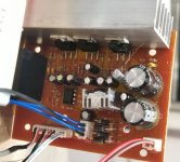
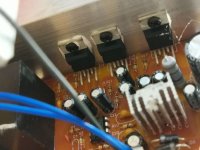
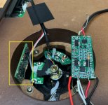
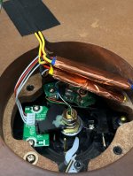
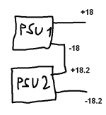
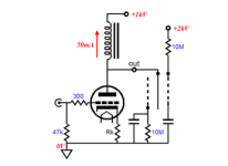
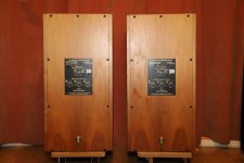
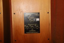
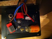
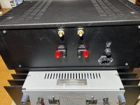
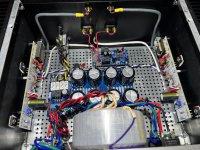
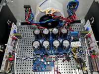
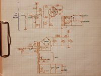
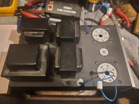
+-10V. Only two fet's start to heat up (no heatsink).

Does anyone have a working offline smps, i would very much like to see some schematics (pcb).

Any assistance would be much appreciated.

Universal Power Supply PCB

I'd like to present here a power supply board that can be used in many different ways. It's been offered for quite some time now with various amp group buys, but the application info has never been consistently gathered in one place.

The most recent version consists of 6 small rectifier boards and 3 main supply boards (two positive, one negative), all separated with scoring lines.

A complete board is available at $30, however, normally I separate it into smaller sections. So, I first remove rectifier strip on the right and then, depending on requirement, I either remove top positive supply board, or lower negative supply board.

In this way, I'm having either a symmetrical amp PS pcb (good for F4, F5, AJ-X amps) or dual positive supply (F2, F3). The remaining positive board can be used to supply small power line stages (like Shigaclone), more on that later.

Dual supply boards are avaialble at $20, single supplies at $10. Small rectifier boards are avaialble free of charge, either added to amp board order or separately.

Attachments

  • 1.jpg
    1.jpg
    195.2 KB · Views: 14,283
  • 2.jpg
    2.jpg
    173 KB · Views: 15,639
  • rect.jpg
    rect.jpg
    191.1 KB · Views: 12,800

Digital Multimeter suggestion?

Hello all! I currently am trying to get into the hobby tech field of vintage audio tinkering. I have a Fluke 115 that I have used in the garage for a few years now, I was thinking to keep that on in the garage and buy a new one for the inside audio work bench. I was looking at a Fluke 177 true RMS, does anyone have any suggestions? I do not want to spend extra money if I do not have to but at the same time, I have always believed that with some things you get what you pay for, for example my precision torque instruments I use when working on cars.

Thank you in advance for your time!

Anyone running the Dayton RS125P full range?

https://www.parts-express.com/Dayto...ference-Paper-Woofer-4-Ohm-295-371?quantity=1

Pretty exceptional response out to 10khz unfiltered and with a little notch at 8k for the mild breakup?……pretty flat out to 12k or so. It’s marketed as a 5” but the actual cone is only 3.25” so off axis response is pretty nice as well. Nice driver for a compact near/mid field speaker on paper.

DD D6.500 FET blew, replaced, had a hot air accident

Hello all,

Had a fet blow, replaced the fet and it was still doing the same thing. I have a scope and all tools, but had an incident with a hot air gun.

I was holding my thermal imager over the driver board, noticed a hot spot on it. When I put my finger on that spot, it stopped restarting so I was pulling individual components. Well as you see in the title, I was desoldering components one at a time, and putting them on the component tester, as I was removing the diodes in the back of the board, a capacitor exploded took some of the 0205 components with it, and now I don't know the polarity of the diodes, or the values of the caps/resistors that went to carpet heaven. I can provide pictures of both boards, and am just curious if this is repairable still.

The highlighted area is what suffered the blow up. The large cap in front is what popped. Yes the one on the mainboard is also burned, but it has been replaced since the pic.

Q12, R125, D5, C21, C27, D11, and a few illegible silks. I've never had this happen to me before, and it is a learning exp, but not one I wanted. haha.

Thanks

Attachments

  • 20231128_123503.jpg
    20231128_123503.jpg
    557.8 KB · Views: 107

UHD player as SACD transport, de-embedder to DAC: Questions.

I’m looking for guidance in regards to using a UHD/Bluray player as a transport for various audio files and SACD discs, connected to a separate DAC.

I found a few boards and boxes that de-embed the DSD audio stream from the HDMI output of a player, and connect to a DAC via I²S on HDMI or DoP on S/PDIF/Toslink.


“HDMI/MHL Interface Audio I2S/DSD/Optical/Coaxial HDMI To I2S IIS for DOP Board”. Capable of I²S on HDMI and DoP64 over S/PDIF and Toslink.
https://www.ebay.com/itm/353354399159


“Ian Canada HDMI to I2S/DoP board”. UFL and XH connector output, 768kHz, DSD256 by DoP.
https://www.audiophonics.fr/en/inte...ipi-receiver-hdmi-to-i2s-dsd-dop-p-13981.html


I would probably use the Topping E50S or D90SE DACs, as either works with DoP, DSD512 and the D90ES has an HDMI input ready for I²S and DSD1024.

Alas, this process is very new to me, so of there is a better solution, by all means step into the discussion and set me on the right path.

I found a reported issue with the black box in the first link, it was that a loud transient could occur when it connected or disconnected from DSD and switched to PCM. That is to say, when a SACD starts or stops, it pops. The Ian Canada board supports higher data, but I have no information about how to use it, or if it works with other non-DSD data like Redbook CDs, etc. Anyone have some experience to share?

Looking for existing speaker design, 15+horn

Hi, I am new here and struggling a bit. I would like to build a pair of speakers to replace my 30 year old 15 inch 4-way party speakers. I am trying to find an existing design that uses a 15 inch woofer and preferably a horn loaded upper. These are for 2 channel audio. I am looking for dynamics, high efficiency, a live sound. I listen to rock, pop, and country. I have a size restriction of 19" wide, 29" tall and 21" deep, due to having to fit them into existing cabinetry. Any help would be appreciated, thanks.

Two Truncated Pentagonal Pyramids for an Enclosure - an interesting Approach to circumventing the intrinsic Disadvantages of Full Range Drivers?

such an approach isn't to find often, but looks interesting - go to
https://www.fairaudio.de/hintergrun...sikelektronic-me-geithain-lautsprecher-2-dwt/
http://www.6moons.com/industryfeatures/roadtourgeithain/geithain.html

Are there projects in this kind ?
Thanks for comments.

Attachments

  • Besuch-bei-Musikelektronic-Geithain.jpg
    Besuch-bei-Musikelektronic-Geithain.jpg
    70.1 KB · Views: 168
  • orgel.jpg
    orgel.jpg
    27.8 KB · Views: 168
  • Like
Reactions: MalVeauX

Roon and Lynx AES16e

I am about to use my newly purchased Acourate correction program.

As a part of the project, I bought a Lynx AES16e sound card, which will feed my 3 x Lyngdorf TDAI2200 with digital signals.
So far, I managed to install the card, which is connected to my NUC via Thunderbolt 3.
I can make test tone work, directly from my PC, but when I use Roon, I run into problems.

Roon displays the Lynx in the Audio folder, and all individual channels, but the “PLAY” botton is faded out; I cannot start playing music.
Roon runs perfect, via my Topping D10s.

When this problem is (hopefully) fixed, I will move on to working with Acourate.

Any idea, what causes the problems?

Rotel RB-960BX upgrade

Hi,

For a wile I wasn't satisfy with the sound quality of my system.
Each week I blamed different component, the speaks, the pre amp or the power amps, maybe I was just looking for a reason to replace it all ;-)

I decided before buying new equipment to give it a try and refresh some of the components of the rotel rb-960bx power amp.
I own two units therefore I will be able to compare between them.

After searching the web for guidance I found that I need to:
1.change the electrolytic capacitors in the power supply
2.change the input coupling capacitors

The power supply capacitors are 50v 1000uf N.C neg.black towa
any recommendation for a replacement?

Also, could you advise on the input coupling capacitors,I am a bit confuse regarding the type and the value.
According to the bom one of them is p.p 100v101h and the second is m.p 100v 104k, I understand that those are Japanese measurement units.
On the board I found 100 100u wima and k100 1818 c7 ero capacitors.

Also do I miss any other components that needed to be replaced?
And no you have any tips for good quality cleaning?

Ferrotec Brand Ferrofluid

I've read the rules and think that I get the gist; I'm not doing this for an income nor a registered business (I'm a well-paid computer-tech' by trade) so lets see how this goes...

This year I found myself in a pickle in attempting to get my hands on ferrofluid: here in Canada, it's (to quote my granny) "as rare as hen's teeth". In fact, it might as well be called "unobtainable", unless you want to send drivers off to a tech' shop and have them do the driver rebuild, or if you throw in the towel and order it from the States or UK.

While that will get you ferrofluid, it'll also get you a jaw-dropping invoice, as all of the purveyors of said ferrofluid will only ship to Canada via courier... which is silly-expensive; on the order of $65 CAD for 100ul. of ferro!

So I got P.O'd enough to say "damn the torpedoes" and ordered enough ferro' to fill 200 syringes with .500ul per syringe - enough for 200 tweeters!

I think that this forum is based in the UK (?) so this likely only applies to Canucks and Yanks, and I'm hoping that a few of them read this excellent site; if you folks need ferro', and want a super fair price on it, hit me up!

Attn' Mods' - if there is a link to kick in a fee for support the board / bandwidth etc., I'm all-in for that! We have a forum / hi-fi marketing site in Canada, but their advertising rates are far more than one selling such a low-profit product as ferro' could ever hope to recoup...

A problem but not DIY My amp just died

I build speakers not amps so please be kind.
One of my Kenwood L-07M monoblocks just died.
I bought them used and I've had them for about 20 years so I guess I can't complain.
They are [ or were] driving the tops in my Tri-amped home system.
Should I try and get a repair done of just buy a new stereo amp of similar specifications?
Any and all suggestions welcome but my budget is severely limited at the moment.
I've owned lots of amplifiers over the years but the old Kenwoods were the best sounding amps I have ever owned

416B sockets?

Call me a bit nuts, but I have a sudden urge to play with some WE 416B tubes. Something about their very high voltage gain intrigues me. I'm guessing they would make a really good phono preamp. Over the years I've picked up a half dozen or so at hamfests and eBay.

Problem is, it's optimized for microwave use, so the plate and grid connections are not your typical pin type of connection, the plate/heat sink is an unusual small top cap connection and the grid is a concentric screw-thread thingy. The heater and cathode are semi-conventional odd-sized base pins.

Does anyone know of any available sockets for these things? Making some from scratch is a bit beyond my ability. Thanks.

Linear 5V dual output power supply with LDO - DIY project

Carpenter and wannabe hifi expert here, from the UK. Apologies for any newbie mistakes in my questions, but here goes:

I would like to build a digital system consisting of the following:

1) linear power supply to power both a...
2) ...streamer (probably raspberry pi based) and...
3) ...DAC (medium output power - enough for floorstanding speakers, not too loud)

The functionality of the power supply would be along the lines of the Allo Shanti. I would like to keep this simple and have two power outputs each at +5V and 3A max, say.

Having reviewed forums here I have decided to go for the following power supply components:

a) toroidal transformer
I am looking at something along the lines of this one with the following specs:

  • 30VA (Is this overkill given I probably would not need more than total of 4A at 5V output? Should I go higher? Is 15VA enough, as this seems to be the standard lower size?)
  • 2 x 6V secondary voltages (Should I go for 7V, bearing in mind I want to use 5V LDOs, as per below?). I quite like the idea to have dual secondary windings and have two identical output pcb boards, connecting indepedently to the transformer. Is this a good idea and what may be better alternatives?

Any recommendations for specific transformers?

b) ready made pcb board
I would like the output voltage to be regulated by LDOs down to 5V, from whatever gets to them. This is where my technical naivety shows, so apologies for that. Why do I want this? Well, it was recommended elsewhere on this forum. Any recommendations for this board design? I will buy all the components separately. Alternatively, any ready-made high quality board recommendations would also be apreciated!

Thanks!

Getting started with understanding and building DAC circuit

Hello Guys, im new here

Im an engineering student with a big interrest in Hifi. Im currently using an old fostex cd play as my DAC in my setup, but i have thought about building my own, high-end dac. I was wondering if you guys have any suggestions on where to start (litterature, schematic etc.) i dont have any particular demands, im just here to learn!

Im a bit ignorant (i guess) when it comes to the digital frontend, and why it can be so damn expensive. I see DACs cost around 3000$ (even way more) and i dont understand why🤔

How might this 6ch preamp be wired?

I’ve been using this 6ch preamp board

IMG_4247.jpeg


To regulate the volume of this 5.1 decoder

IMG_4248.jpeg


because the 5.1 decoder’s output needs pre amplification and the IR is randomly affected by the TV’s remote. I can use the TV’s variable analog output to control volume but of course only with analog input to decoder providing suto surround. Using optical I loose the tv control and as a result use the 6ch preamp for signal magnification and control.

The preamp serves it’s purpose well, no cross IR remote codes causing mischief, volume control, and adequate signal magnification. However it’s seemingly not a very well built unit. The usb-c power input broke off and required soldering and the subwoofer level adjustment jumps all over the place, the potentiometer dial isn’t super accurate as it is. Seller has nearly perfect rating but the repair would take forever and it still might be a fixed troublesome unit.

I’m looking at some other compact 6ch preamps that have a nicer display that better matches the decoders display. The two others I see both have what looks like jst connectors but with a common ground. If I were to give one of these a go, how would I wire it with only one ground spot? I’m really still quite green behind the ears with this end of the hobby and my only idea would be to splice the six outputs grounds into one wire going into that ground location. The reason I bought the original preamp was because the grounds were internally connected with a straightforward connection. I yanked the rca’s and added these phoenix connectors for simple 3 conductor wire connecting between the two boards and amplifiers.

IMG_4211.jpeg


IMG_4212.jpeg


Here’s one I'm looking at

IMG_4250.jpeg


IMG_4249.png

Coaxial center channel or MTM

I am going to build a center channel for my nomex 164 mk2. I have a hypex fa 122 2channel plate amp with a dsp that i intend to use as x over.
I was thinking that a good Coaxial driver would be a good fit with better off axis response than a ”normal” mtm center channel but i cant really decide and would like to know the thoughts from more knowlagable people.
The new sb acoustic mt19cp looks interesting?
Its worth noting that i live in a apartment so i will never reach any high spl

Build report: Tube preamp for bass (or guitar)

Hi,

I built the first version of this amp in 2013, but I was never quite satisfied with the results (it was my first tube project, and you know how it is with first projects). When I finally got around to fixing the things that bothered me, I unsurprisingly ended up rebuilding the whole thing pretty much from scratch. This amp is designed for bass, but it works very well with guitar too.

This time I'm very satisfied, so I thought I'd share this project in hope that it can be of use for somebody. Feel free to build this project or clone parts of it, or whatever. The schematic and layout chart should be correct, although you will have to fiddle with the power supply resistors to match your power trafo.

One of my main goals was to make a silent design (my old version was a bit hum prone), so I paid attention to lead dressing, included a humdinger in the heater supply and put in circuitry to separate audio and chassis ground. The tubes are TAD low noise tube, and the power trafo is a toroid. It also has a (ground liftable) DI output. It's not HiFi-silent, but plenty silent enough for stage or even studio work. The slight hiss from the resistors is the loudest noise, and that's fine by me.

I decided not to invent the design ground up, as I didn't have the time needed for this kind of trial-and-error approach. Instead, I wanted to find a proven design and use that as template for this build. After browsing through lots of schematics and listening to youtube reviews of different vintage tube amps, I landed on the Marshall JCM 800 Bass Series. The preamp stage is simple enough, and it seemed to have an interesting tone stack (not a fender type, which I dislike in a bass amp). You can check out the JCM schematic here for reference: Marshall-JCM800-1986.gif

I did some small modifications, and substituted the phase inverter with another gain stage and a cathode follower for low impedance output. The extra gain stage is a bit redundant, and I had to tame the gain a bit not to get to much overdrive, but it ended up working fine. (Also, I couldn't come up with any other use for the left over triode from the cathode follower).


Schematic:
schematic.png


The tubes are V1: TAD 12AX7WA-R, V2: TAD 7025 WA and V3: TAD 12DW7/7247. The voltage from this trafo is a bit high so the first supply filter stage is a bit drastic with a voltage drop of over 100V, but this was the trafo I had handy. Also, being a toroid and rated for 100mA, the current draw of this amp is not enough to drop the voltage to the nominal 280VAC. For a similar build, you could go with a smaller power trafo.

Layout:
layout.png


Guts:

inner.jpg


This is what it looks like in the rig, with new knobs and labels (the power amp shown is another project of mine, built around a Hypex UcD2k, more info in this thread: Hypex UcD2kOEM Bass Power Amp Project)
front.jpg


I'd be happy to answer any questions!

/Fredde

Clamping stand-mount speakers to the stand ...

Woke up today with a question in my mind - what would happen if I took a couple of long clamps and put them on the back of the speakers to clamp them down to the stands..... The clamps go between the top of the speakers, where I've also added a couple of 3mm aluminium squares 150x150mm, and the bottom side of the metal top plate of the stand.

So I tried it out. Quite a difference! Very audible increase in clarity and dynamics. And the words of lyrics have become easier to hear, together with low level detail I hadn't heard before on tracks. The sound is clearer and more percussive - accents are more pronounced. The drum kit in particular is more dynamic. You might expect the difference to be in the bass, but it isn't - it's in the mids and treble. The bass is a little tighter but because of the brighter mids it has gone back a little in the mix. It's not deeper, but you wouldn't expect that.

Speakers are Mission 761, sealed box 10.2 litres, 6.5" and 19mm tweeter. Stands are very solid Atacama SLX 600.

Has anyone else tried this? If you have a couple of long clamps I suggest you try this out. The difference in my case isn't subtle. I'm going through all my favourite jazz singers and having a ball.

IMG_5808.jpg

First Watt M2 Clone

M2 Power Amplifier
Hand matched Mil-spec parts to less than 1%
Soft Start board
Speaker Protection board
Audio Grade caps
IEC power jack with RF filtering
Oversized wire and toroidal transformer mounted to faceplate which is not an easy task.
Bridge rectifiers mounted to alum faceplate for best heat dissipation
Biased perfectly

The commercial version is $4000 The First Watt M2 is a two channel audio power amplifier delivering 25 watts per channel. It uses JFET and MOSFET transistors operating in Class A mode without negative feedback so as to produce a more musically life-like sound.

Spent most of its life in the closet after I built the GM70 tube amps a few years ago.
I built it for the Khorns but the GM70s won (at 10x the cost)
Built by a 40yr veteran

Total $780 plus freight

Attachments

  • 7F1143E0-F2E5-4FB3-9BF5-46224F624D17.jpeg
    7F1143E0-F2E5-4FB3-9BF5-46224F624D17.jpeg
    394 KB · Views: 308
  • 3F163095-815F-4ACE-A4A2-87F960CCE708.jpeg
    3F163095-815F-4ACE-A4A2-87F960CCE708.jpeg
    563.2 KB · Views: 330
  • 23389FE7-6A5B-475C-B67E-B277DB4D7D6D.jpeg
    23389FE7-6A5B-475C-B67E-B277DB4D7D6D.jpeg
    597.8 KB · Views: 349
  • 1BEBDDDA-5A34-4594-8D27-E099606002B9.jpeg
    1BEBDDDA-5A34-4594-8D27-E099606002B9.jpeg
    697.7 KB · Views: 366

Dim bulb current limiter fixes buzzing amp?

Hello folks,

My amp has intermittent 120Hz buzz, it happens on both channels but not at the same time, and it happens very often when the amp is powered on when cold; it usually subsides as the amp gets to its normal temperature. It was worse a couple years ago, I changed power supply caps for the regulator section that were closest to the power transistors, suspecting heat-induced reduced lifetime. It fixed the problem for a while but it slowly returned. The amp is almost 35 years old so I'm pretty sure all electrolytics will have to be changed.

I live in a rural area that has pretty crappy utility service, probably old transformers now undersized for their load, and there's a lot of trees so we often get very short losses of power (less than a second), probably due to tree branches shorting the wires momentarily - It happens mostly when it's windy. Sometimes there are two of them within a couple minutes. Yes, the power company is pretty lousy on network maintenance... 😡

These can't be good on my amp that has no "zero-crossing" switching like many modern equipment. After the last one of these there was a louder than usual buzz on the left channel, a bit on the right, and it doesn't subsides - So on the bench the amp went. Tracking the buzz I find that there seems to be a problem on the negative rail of the regulated supply. Positive rail is fine, so the shared voltage reference is ok. The ripple on the negative rail is higher than the ripple on the corresponding input caps, so I directed my attention to the final caps. The very lower buzz on the right channel probably suffers from the resulting noisy ground.

I was preparing to add a new cap in parallel temporarily to test my theory but then I thought I should set up a "dim bulb" current limiter. I used a 100W bulb to test the setup first without my cap mod, there was an expected bulb glow due to inrush current, but after the main caps charged the amp stabilized and the buzz was gone! Hooked the O-scope and everything seems normal, the voltages are what they're supposed to be, played music and sounds ok... However can't crank the power up because the bulb gradually kick in.

How can added resistance on the mains input cure a buzz? The hot line goes from IEC jack to a 6A fuse, power switch and splits to the two toroid transformers - That's it. I can only think of an oscillation occurring, it may be still be related to caps aging with higher ESR, but I'm at a loss. What do you make of this? Should I try insert a NTC thermistor at the mains input?

Thanks,
Joris

trouble linking transistor stages

hi everybody
i have been 'trying' to experiment with transistor amps but cant seem to link one stage to another. i am using bc337-25's on a bread board with trim pots to adjust as needed. with a single transistor everythings fine, but when i try connecting the second stage it fails.
if anyone knows of any good articles/books that cover this specific subject, please let me know.

warm regards
gaz

sweet lil 6N2+FU-32 amp - questions

picked this neat lil ChiFi headphone/speaker amp up at an antique faire, looking to get it working well for my parents so they can use the passive speakers in the walls in the place they just moved into!

nothin too fancy, but decent iron, and everything's there that needs to be. haven't started it up yet, testing through some 832A's and 6N2P-EV's first, and i'd like to understand some basic things about how to properly load this amp first, as well as how to pick a good set of headphones to pair with it.

i mostly work with guitar amps and heavy overdrive, so i am unused to circuits like this with significant power output, but where there seems to be a wide flexibility for what's an acceptable load. the impedance ratio for the output transformer indicates there would be a 1,420 ohm primary impedance with a 4 ohm speaker and a 2,840 ohm primary with an 8 ohm speaker; without seeing a triode mode plate characteristics graph or having suggested load resistances in the datasheet, i guess these seem like friendly numbers, maybe a bit low?? and the way i read the 100R resistor and switch network for the output is this: the shunt resistor is there to ensure the load is never greater than 100 ohms even if nothing is connected, and the series resistor with the headphone output ensures the load is always between 50 and 100 ohms when headphones are connected. my questions are:

first off, are secondary loads all the way from 4-100 ohms really okay? and is there an ideal range within that range? i'm used to much higher loads being untenable due to the potential for the signal swing to exceed screen dissipation maximum on the low plate voltage side, and exceed plate voltage maximum and/or OT or power supply voltage maximums on the high plate voltage side. i know we're at very low plate voltage considering the max for the 832A and what the filter caps are rated, but i figure with a few volts at the input like from a CD player or something, the 6N2P-EV could easily deliver a few tens of volts to overdrive the 832A's, and my parents aren't too picky, their hearing is going, and they like it LOUD haha! so i figure there's a possibility those overdrive conditions could happen.

second, (and these are total noobie questions) how can only a pair of headphones dissipate all the power on the OT secondary? do they rely on their higher impedance values, aided by both 100R resistors, to limit the current enough to not damage them? when picking out headphones, should i verify their power handling capability can handle the amp? or should i only worry about it with lower impedance headphones?

third, if loads from 4-100 ohms are really okay, i can't really see any reason to have this speaker/headphone switch... i don't see any detriment to having headphones and speakers connected at the same time. can i just disconnect it or use it for something else? i was thinking of attaching the other OT secondary for use with 2-4 ohm loads and turning the switch into a selector between the two windings.

lastly, i'd like to try 829B tubes with this amp, but i want to make sure i don't exceed component ratings. as far as the B+ current, based on the choke reading 125DCR, i'm not comfortable pushing it above about 80-100mA, so i may have to step up the cathode resistors to keep the current lower. for the filaments, i know i wrote "6.3V - 0 - 6.3V" and then "6A", but as you can see the transformer actually says "6.3V/3A - 0 - 6.3V/3A". so here's another noobie question - does that mean that both windings used together for 12V can handle 6A, or can they still only handle 3A?

one more lil question - if this is receiving a phonograph signal, is it still adviseable that you use a designated phono pre between the phonograph and the amp, for additional signal amplification and/or RIAA filtering?

cheers! happy holidays!

Attachments

  • 20231128_040417.jpg
    20231128_040417.jpg
    260.1 KB · Views: 169
  • 20231118_233414.jpg
    20231118_233414.jpg
    349.8 KB · Views: 162
  • 20231118_232950.jpg
    20231118_232950.jpg
    456.4 KB · Views: 131
  • 20231118_195430.jpg
    20231118_195430.jpg
    309.2 KB · Views: 131
  • 20231118_233439.jpg
    20231118_233439.jpg
    227.8 KB · Views: 126
  • 20231118_233422.jpg
    20231118_233422.jpg
    165.5 KB · Views: 158

Restore advice please - Yamaha A-760 Amplifier

Hello fellow DIY'ers,

I've recently inherited a Yamaha A-760 Stereo Amplifier, this has been in our family since new from the early 80s. I'm totally aware of the well-known incandescent bulb issue which I will aim to address once the other issue has been resolved, that being, the phono channel having very very poor sound quality.

This amplifier has very recently had the safety recall work done. Now that it has a clean bill of health from a safety perspective, I would like to carry out a full restore project on it. The most common of restore projects would include a full re-cap, this is the easy bit! What else would you guys recommend that should/could be replaced? Do any other components need replacing given this unit is over 40 years old?

Thanks in advance guys

forgot to say - apologies if I posted this in the wrong section on the forum, please let me know which section it should be for next time - Thanks

New aspiring tech!

Hello everyone, new here and a hungry aspiring tech! I really am saddened to see that not many people service (properly) around my area and even times I have had service it left a little to be desired. That being said, I am not expecting to be able to learn decades of tech experience over night but I want to start learning. I have nothing but time and dedication so why not. I have a perfect opportunity to get started as my Crown amplifier recently failed.

Anyhow! Question is, can any experts give me some advice as what tools to purchase. At the present moment I have a Weller Digital Soldering Station - WE1010NA, a Fluke 115 DMM but I think I will need at some point at least a signal generator, an Oscilloscope, Voltage monitor, filter, probably more? I do not want to go drop thousands of dollars but just get an idea of what I need to get started. Thank you!!!

Group of 4 inch driver performance evaluation: an IMD perspective

Nowadays there's no short of information about driver's harmonics distortion. For example when we compare Scanspeak 15WU/8741T00 vs SBA SB15CAC30 from a famous German DIY magazine, it's pretty easy to see both are great drivers, but SB15 seems to be a slightly better in all regards. After all, SB15CAC30 is better at 3rd harmonics(HD3) in all frequencys, and equal or better 2nd harmonics(HD2) thanks to a more stiff cone. So conclusion is pretty clear right? As long as you are ok with 5mm xmax, SB15CAC30 should be a better driver:
SB15vs15WU.png

Until I'm interested to do a 30hz+255hz(4:1) test my self. Test condition is not ideal but made as fair as possible. I test free raw driver with nearfield MIC, same distance for both driver, with about 3.5mm~4mm one way excursion on SB15 and match the bass tone(not voice tone) on 15WU. After all, voice tone is 12db lower in voltage and should be handled easily for both drivers. Both drivers are my own collections so there's no need for bias here. Here's the result:

SB15:
SB15NAC_imd.gif


15WU/8741:
15WU_imd.gif


Not only SB15 shows much higher HD2, HD3, IMD2, IMD3; but the waveform is visually distorted, which is a bit shocking here. Considering the price, 15WU in this particular test is clearly another class or two higher than SB15, which it should be, but considering SB15 metal cone drivers doing so well in almost all DIY audio tests and is regarded so highly, and 15WU is generally regarded not so well by DIY community, this is still a bit surprising.

So I decided to do similar tests for my 4 inch driver collections, but with 80hz+680hz(4:1). I choose these frequencies because 80hz is higher than most driver's FS in this group, can produce reasonable loud SPL in home use. I pushed the drivers to around 2.5~3mm XMAX one-way so that it stayed within most driver's linear excursion range(except W4-2142). I use Linkwitz ranking system to give each driver an average score by their ranking in each category, instead of a subjective ranking. Most ranking are quite straightforward, but I want to add another one: Amplitude stability. I'll explain how it works:
am_test.png

In this graph, I compared the voice tone amplitude for the ones from bottom and top bass tone respectively, and derive a score by its min/max. In this example, bottom voice tone is 62 pixel height, and top one is 57 pixel height, thus got a score of 92% in amplitude stability. This is still very rough, but is easy to do, and at least provide a bit of information. This test should be mostly indicative of BL curve symmetry, but also probably reluctance force modulation. To be honest I'm not sure.

Another note: In IMD rankings, I bias more on IMD components on the LEFT. on the right it should be easily masked just like HD2.

Here are the results:

Peerless NE123W:​


NE123w.PNG

Wavecor WF120BD01:​

WF120BD01.PNG


TB W4-1757SB:​

W4-1757sb.PNG


SB Acoustics SB12PAC25:​

SB12PAC.PNG


TB W4-1052SD:​

W4-1052sd.PNG


TB W4-2142:​

W4-2142.png


TB W4-1337SD:​

W4-1337sd.PNG


Dayton CF120:​

CF120.PNG


TB W4-1720:​

W4-1720.PNG


Peerless HDS 830854:​

830854.PNG


Here's a score table:​

Amplitude StabilityBass HDVoice HDIMD2IMD3AM RankingOverall
W4-2142
96.20%​
7​
6​
3​
2​
2​
4​
NE123W
95.30%​
9​
3​
4​
6​
3​
5​
W4-1720
96.90%​
10​
2​
5​
3​
1​
4.2​
CF120
90.70%​
6​
9​
7​
10​
6​
7.6​
W4-1337SD
90.50%​
5​
5​
6​
8​
7​
6.2​
W4-1052SD
87.80%​
8​
4​
8​
9​
8​
7.4​
SB12PAC25
82.90%​
3​
10​
9​
4​
9​
7​
W4-1757SB
93.80%​
2​
1​
2​
1​
4​
2​
WF120BD01
81.80%​
1​
7​
10​
5​
10​
6.6​
830854
93.30%​
4​
8​
1​
7​
5​
5​

And my IMD-biased rankings and comments:​

1: W4-1757SB: Clear winner in this test. Great low distortion underhung driver.
2: W4-2142: Performs very well, also underhung driver despite smaller XMAX.
3: W4-1720: Huge underhung motor, very bad HD but decent IMD. Honestly I expected it to perform much better in this test.
4: 830854: Very good driver, and it performs slight better than the NE series from the same company.
5: NE123W: Good performer, I didn't expect it to do well in IMD test due to poor-ish Klippel tests in this series. But holds up well.
6: W4-1337SD: Another good performer. I expected it to do better, but IMD3 is not very good.
7: WF120BD01: Wavecor has excellent reputation in almost all non-linear tests, and ZaphAudio regarded it as an high-end all-rounded driver, but in this test it's a bit disappointing. IMD2 is particularly high.
8: SB12PAC25: Exceeded my expectation, considering this driver has no shorting rings, very close to WF120BD01 which has a fancy motor.
9: W4-1052SD: Ok performer. Considering the HD test is pretty good, IMD performance is a bit disappointing.
10: CF120: Worst in this group, a bit shocking considering this driver has copper cap in motor and has long throw. Actually I feel this driver is not bad at all, maybe the 80hz bass tone caused some unfortunate air turbulence out of the tiny hole on the back the driver. Higher or lower frequency it performs better.

That's all. Thank you!

Edit: Peerless 830854 has been added.

Fosgate RCA connector

Does anyone have a source for these rca connectors in the US? Off a Fosgate t1500-1bd. It’s the current style heatsink but before they went to the bdcp amps

The original has two white jacks on one connector and two red in the other. Those would be even better but I won’t be picky about color. Only ones I could find were from someone selling out of Israel so shipping was way high.

I’ll happily take used in good condition if someone had a parts amp.

Attachments

  • IMG_2053.jpeg
    IMG_2053.jpeg
    51.5 KB · Views: 76

Current driver for Haruna or other front-exit 6"?

I've been looking for some kind of preferably front-exit horn setup in the 6" driver range. The closest analogue to what I'm looking for would be a 6" version of the Dallas II, except the D2 has so many odd angles it pretty much requires a table saw that I don't have. Something like the Haruna would be easier for me since I could get CNC cut flats w/ grooves in the sides. I'm thinking front-exit may be a better idea because the corners shapes in the room are pretty awkward and asymmetrical.

So two questions:

A) The Haruna calls out the FE166en that isn't available anymore. Just briefly looking at the T/S parameters, it looks to me like the FE168EZ would be closer than the current FE166NV2, but I might be looking at the wrong parameters. I noticed very few horn designs I've seen ever call out the Sigma series. Any particular reason for that?

B) Is there an obvious other front-exit horn design I'm missing? 8" like the Dallas 2 would be OK (as long as it's not wider than 12", ideally <11"), but the Dallas design is just not practical for me to construct.

EDIT: Anecdotally, I have a soft spot for front-exit horns, and especially double front-exit Fostex ever since I heard the Cain & Cain BENs at VSAC a million years ago. I had the room across the hall from them and vividly remember thinking as I first walked past "How/why on earth did they bring an actual piano to the show?" before I realized how incredibly stupid that was. I made a lot of stops back in that room at the show that year.
Projects by fanatics, for fanatics
Get answers and advice for everyone wanting to learn the art of audio.
Join the Community
507,921
Members
7,893,618
Messages

Filter

Forum Statistics

Threads
406,486
Messages
7,893,618
Members
507,921
Latest member
bedomes