You are using an out of date browser. It may not display this or other websites correctly.
You should upgrade or use an alternative browser.
You should upgrade or use an alternative browser.
Filters
Show only:
Danley BC Subs Revisited
- Subwoofers
- 14 Replies
Someone on Facebook was asking about the Danley BC subs, and I personally think that the concept is fairly straightforward, and it's come up on FB a few times so I thought I'd do a quick "brain dump" here.
On Facebook, I (sorta) joked that: "'Boundary Coupled' is just marketing speak for "the baffle is really big.'"
So let's elaborate on this a little bit:
First off, the primary reason that radiator has higher output on axis when it's on a horn or waveguide is because the waveguide takes the output from a radiator and constrains it into a narrower beam.
This is no different that now a light bulb can barely illuminate a room, but a ten watt diode laser can cut through wood:


A diode laser takes it's energy and focuses it in a point, a woofer in a baffle that is sufficiently small will radiate in all directions (spherical) and if you put a radiator onto a big flat baffle, the baffle itself will keep the energy from radiating backwards.
Next thing that we do is figure out "What is that frequency?"
Danley BC-218 measures five feed wide by five feet tall by 2.5 feet deep. That's a baffle face of 152cm x 152cm. The exit of the BC218 is NOT in the center of it's baffle, and that has an impact, but describing that effect is beyond the level of this discussion. (You can sim it in ABEC or VituixCad.)
This next thing is pretty important I think: Keep in mind that the radiation from the radiator has to wrap around the enclosure before it can radiate in 360 degrees. If we just looked at the front of the baffle, we could constrain radiation down to 224Hz. This is because the front of the baffle is 152x152cm and 224Hz is 152cm long.
BUT - once we include the sides of the enclosure, we're looking at radiation control down to 112Hz. That's because the additional thirty inches, on each side, increases the baffle size to 120 inches wide.
Now at his point you're probably wondering "what's the point of a subwoofer that "controls radiation" down to 112Hz?"
The answer to that, for the Danley BC Subs and Danley's B-DEAP subs that he made at Sound Physics Labs, is that they're really designed to be arrayed. That's why I didn't do a deep dive into the mouth location. The subs don't make a lot of sense when used in singles. Add a second BC-218 sub and you're controlling radiation down to 56Hz, easy.
The next step in this, is that once you place the sub on the floor, the floor itself increases the on-axis efficiency. This ALSO gets tricky, because the floor isn't a perfect mirror of the loudspeaker. But chances are good that you will be putting your speaker or subwoofer on a floor, so it stands to reason that you would want to leverage it to improve the performance of your speaker.
On a side note, if it's not obvious, you could avoid a lot of this by just cramming a subwoofer into a corner. But BC subs arguably are best outside or in a big room, where that huge baffle can constrain radiation. I think this is particularly important for festivals where you don't want the subwoofer to "bleed" into the next stage over, or the stage behind it.
I think it's also useful for clubs and the like, because it's controlled radiation reduces energy radiated into adjacent buildings.
On Facebook, I (sorta) joked that: "'Boundary Coupled' is just marketing speak for "the baffle is really big.'"
So let's elaborate on this a little bit:
First off, the primary reason that radiator has higher output on axis when it's on a horn or waveguide is because the waveguide takes the output from a radiator and constrains it into a narrower beam.
This is no different that now a light bulb can barely illuminate a room, but a ten watt diode laser can cut through wood:
A diode laser takes it's energy and focuses it in a point, a woofer in a baffle that is sufficiently small will radiate in all directions (spherical) and if you put a radiator onto a big flat baffle, the baffle itself will keep the energy from radiating backwards.
Next thing that we do is figure out "What is that frequency?"
Danley BC-218 measures five feed wide by five feet tall by 2.5 feet deep. That's a baffle face of 152cm x 152cm. The exit of the BC218 is NOT in the center of it's baffle, and that has an impact, but describing that effect is beyond the level of this discussion. (You can sim it in ABEC or VituixCad.)
This next thing is pretty important I think: Keep in mind that the radiation from the radiator has to wrap around the enclosure before it can radiate in 360 degrees. If we just looked at the front of the baffle, we could constrain radiation down to 224Hz. This is because the front of the baffle is 152x152cm and 224Hz is 152cm long.
BUT - once we include the sides of the enclosure, we're looking at radiation control down to 112Hz. That's because the additional thirty inches, on each side, increases the baffle size to 120 inches wide.
Now at his point you're probably wondering "what's the point of a subwoofer that "controls radiation" down to 112Hz?"
The answer to that, for the Danley BC Subs and Danley's B-DEAP subs that he made at Sound Physics Labs, is that they're really designed to be arrayed. That's why I didn't do a deep dive into the mouth location. The subs don't make a lot of sense when used in singles. Add a second BC-218 sub and you're controlling radiation down to 56Hz, easy.
The next step in this, is that once you place the sub on the floor, the floor itself increases the on-axis efficiency. This ALSO gets tricky, because the floor isn't a perfect mirror of the loudspeaker. But chances are good that you will be putting your speaker or subwoofer on a floor, so it stands to reason that you would want to leverage it to improve the performance of your speaker.
On a side note, if it's not obvious, you could avoid a lot of this by just cramming a subwoofer into a corner. But BC subs arguably are best outside or in a big room, where that huge baffle can constrain radiation. I think this is particularly important for festivals where you don't want the subwoofer to "bleed" into the next stage over, or the stage behind it.
I think it's also useful for clubs and the like, because it's controlled radiation reduces energy radiated into adjacent buildings.

Power Amplifier Board local power rail bypass question
- By radio_free
- Solid State
- 3 Replies
Hello Everyone,
I am trying to modify a project my father was working earlier, the question I am having now is on local power rail bypass.
I know there has been a lot of discussion on bypass and I know bypassing at the cap bank is no no, but a good practice to have local bypass if the main cap bank is some distances (maybe inches) away.
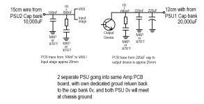
I will be doing 2 PSU for each amp board, one to drive the output stage with a bigger PSU, and one smaller PSU to drive the input and VAS. Both PSUs are approx 12~15cm away from their respective power entry points on the amp board. Each power rail is 35VDC, from 25v transformer secondaries.
The bypass method I am using is have in mind is really a copy from an article from TNT Audio by Dejan Veselinovic. What I think is good is the RC right before the device.
Main questions I have are:
1. Should I also have the 220uF bulk filter cap for the PSU2 (driving Input stage and VAS)? Currently I have no plans to but I can still add in if that is a good thing.
2. Which is preferred (X7R SMD type or MKP box THT type) for the 100/220nF bypass as well as the 680nF RC filter? Their cost difference is really very small for DIY, and while X7R is smaller in footprint, I am doing double layer board so space is not really an issue.
Hope to get some feedback soon as I'll be having a one-week break soon, and will be a good time to make some progress.
I am trying to modify a project my father was working earlier, the question I am having now is on local power rail bypass.
I know there has been a lot of discussion on bypass and I know bypassing at the cap bank is no no, but a good practice to have local bypass if the main cap bank is some distances (maybe inches) away.
I will be doing 2 PSU for each amp board, one to drive the output stage with a bigger PSU, and one smaller PSU to drive the input and VAS. Both PSUs are approx 12~15cm away from their respective power entry points on the amp board. Each power rail is 35VDC, from 25v transformer secondaries.
The bypass method I am using is have in mind is really a copy from an article from TNT Audio by Dejan Veselinovic. What I think is good is the RC right before the device.
Main questions I have are:
1. Should I also have the 220uF bulk filter cap for the PSU2 (driving Input stage and VAS)? Currently I have no plans to but I can still add in if that is a good thing.
2. Which is preferred (X7R SMD type or MKP box THT type) for the 100/220nF bypass as well as the 680nF RC filter? Their cost difference is really very small for DIY, and while X7R is smaller in footprint, I am doing double layer board so space is not really an issue.
Hope to get some feedback soon as I'll be having a one-week break soon, and will be a good time to make some progress.
Attachments
Boston Acoustics PV800 Sub Bash Amp Needs Help
- By DavidKS
- Subwoofers
- 3 Replies
Hello All,
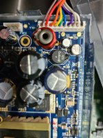
Got a Boston Acoustics PV800 Subwoofer needing some help. I really like this sub and would like to save it if possible. I know that it is a BASH amp and that I have very limited knowledge and skills. I probably know the names of about 25% of the components involved and I know a guy who can solder pretty well. I'll give a description of it's behavior and what I know and and have done so far. Hopefully someone here sees or reads something here for a fix.
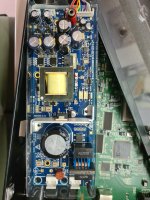
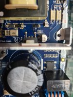
Plugging the sub to power usually results is a dim (about 20% of expected brightness) LED indicator. This is regardless of the subs power switch setting (on, auto, off). If the switch is "off or auto" you get dim red, if the switch in "on", you get dim green. This sometimes give a faint, shrill squealing type sound from the sub. When powering on to a dim LED indicator you always get 160V from the power supply board (see circled areas in pics). . . the board that receives the 160V will then always output ~12V (see circled area in pics)
When the sub gets plugged in and works, of course the LED behaves as it should. The one other obvious difference is that the board that was outputting ~12V is now outputting ~30V
When the sub doing the dim LED behavior, I can jump start the sub as follows. For about 4 seconds, I run a hair dryer on the left half of the BASH labeled board then plug in the power cable. Sub immediately comes to life. If I now leave the properly working sub plugged in overnight and everything get warmed up, unplug the sub then plug it back in. . . I get the dim LED fail again.
There is only one repair that I have done (and it didn't change the behavior). In one of the circled areas in the pics, there were two transistors that had their faces blown off, I had them replaced.
Thoughts anyone?


Got a Boston Acoustics PV800 Subwoofer needing some help. I really like this sub and would like to save it if possible. I know that it is a BASH amp and that I have very limited knowledge and skills. I probably know the names of about 25% of the components involved and I know a guy who can solder pretty well. I'll give a description of it's behavior and what I know and and have done so far. Hopefully someone here sees or reads something here for a fix.
Plugging the sub to power usually results is a dim (about 20% of expected brightness) LED indicator. This is regardless of the subs power switch setting (on, auto, off). If the switch is "off or auto" you get dim red, if the switch in "on", you get dim green. This sometimes give a faint, shrill squealing type sound from the sub. When powering on to a dim LED indicator you always get 160V from the power supply board (see circled areas in pics). . . the board that receives the 160V will then always output ~12V (see circled area in pics)
When the sub gets plugged in and works, of course the LED behaves as it should. The one other obvious difference is that the board that was outputting ~12V is now outputting ~30V
When the sub doing the dim LED behavior, I can jump start the sub as follows. For about 4 seconds, I run a hair dryer on the left half of the BASH labeled board then plug in the power cable. Sub immediately comes to life. If I now leave the properly working sub plugged in overnight and everything get warmed up, unplug the sub then plug it back in. . . I get the dim LED fail again.
There is only one repair that I have done (and it didn't change the behavior). In one of the circled areas in the pics, there were two transistors that had their faces blown off, I had them replaced.
Thoughts anyone?
Extra-compact midrange drivers - TC5FC07 or FR040WA01/FR040WA02
Thinking about using 1 or 2 of these on each side for a nearfield monitoring application, in between a TC9FD18 and NE19VTS. Crossover points likely 900 Hz and 2 kHz. Yes, would have them as 4-way monitors if this comes to fruition. Reason for these two drivers specifically is because they look pretty good and because I need the minimum size possible that is "lower" than a tweeter; I want to achieve, as close as possible, a point source on a flat baffle.
Any thoughts as to which of the two might be better-performing?
Any thoughts as to which of the two might be better-performing?
Steel Angle as Toroidal Transformer bracket - Steel thickness?
- By Sadface
- Construction Tips
- 21 Replies
G'day Guys,
I am intending to use some 125x75 mild steel angle as a bracket to mount a Toroidal transformer on its side.
My local supplier has 6mm, 8mm, 10mm and 12mm thickness available.
12mm seems a bit silly. Its only a 300VA transformer.
Is 6mm going to be rigid enough?
10mm also silly?
8mm a happy medium?
Just go with the 6mm?
Cube Audio FC8 - has anyone built with these?
- By Bryan S.
- Full Range
- 15 Replies
I'm planning a new build and going the route of full range drivers. Not sure if the new speakers will be OB or in a box. I was very interested in Lii at first, but in looking and reading I came across the Cube Audio drivers, especially the FC8 which is their least expensive offering. They look the part and reviews of their finished speakers are all very good. Has anyone used the FC8? I'd love to hear any impressions. I have a feeling even their cheapest driver will outrun the best Lii has to offer.
My version of an Ultrasonic Record Cleaner
- By bbftx
- Analogue Source
- 2336 Replies
I've had a VPI HW-17 record cleaner for some time, but have always wondered if there was a way that could deliver better cleaning results along with less contact with the vinyl . So, after reading threads here and elsewhere about using ultrasonic cleaners to get the dirt off of vinyl, I thought I'd rig up my own unit.
I started with an ultrasonic cleaner that uses 60 KHz transducers. It was a little harder to find and a little more expensive than the typical 40KHz Chinese-made units, but the higher frequencies theoretically do a better job at cleaning the very small grooves of a record and there is less risk of damaging the vinyl from the cavitation. Those two points are a big advantage of 60khz units over 40khz units.
To rotate the records, I wanted to minimize motion in the cleaning solution. My target was a 4 minute cleaning time for the vinyl surface. Given that about 1/3 of the record is submerged in the solution at any moment, the math told me to find a 5 revolution per HOUR synchronous motor. Synchron makes such motors in almost any rph or rpm you could want. The 5rph motor yields a 12 minute rotation time. My plan is 1 rotation = 1 cleaning cycle.
I fashioned a spindle out of 9/32 W1 drill rod. It was was easy to machine a 1/8" diameter hole in one end of the spindle on my lathe to fit over the motor shaft (1/8" diameter).
The motor and shaft are mounted in place using an electrical connector box and conduit. The arm is mounted to the ultrasonic unit using L-brackets and pipe straps. The setup allows the motor and spindle assembly to be rotated up to load records, and then rotated down into the bath.
My spacers are 4" diameter, 1/2" thick cork rounds. [Oct 2012 note: I have since found different spacers, which are much better: I've ordered these from the UK: 110mm by 105mm tapered cork stoppers - they cover the record label completely and very little of the lead out groove. They are just a touch over 1" thick, which is optimal spacing.
No.37 Natural Cork Stopper 110mm from Just Cork No. 37 Large]
[Dec 2012 Note: I added a sintered bronze bearing and a bearing housing to support the weight of the spindle, records and spacers, and eliminate the bending moment on the motor shaft.]
I'll report back after I clean and play some vinyl. My first batches will use distilled water and isopropyl alcohol at about 7 to 1 [Sep 2012 note: I've since gone to a much lower concentration of isopropyl, about 50 to 1] , with a few drops of Kodak PhotoFlo. This solution, combined with the very slow rotation, will allow the liquid to drain off the vinyl surface very easily.
The cleaner can still be used for any items you'd normally put in an ultrasonic unit. It does a great job on some fairly intricate gold jewelry I've cleaned.
Photos below. Questions and comments welcome.
[Feb 2013 Note: I have built a second, sturdier design using a metal frame and hinge assembly that fits over the top of the Ultrasonic cleaner. Here is a direct link to the description later in this thread:
Version 2 of BB's URC
And here's a direct link to the post with the parts list for Version 2:
BB's URC Version 2 Parts List ]
Feb 2015 Note: I've built a 3rd version, designed to be assembled with fewer tools and be more adaptable to different cleaners. Description and pics for Version 3 start here:
BB's URC Version 3
Parts list for Version 3 reposted here: BB's Version 3 Parts List
Happy building.
Cheers,
BB
View attachment 297136View attachment 297137View attachment 297139View attachment 297140
View attachment 297141View attachment 297142
Transmission Line Modelling Software
- By schmeet
- Software Tools
- 976 Replies
Hi guys,
I know you all have tools that you use (and the creators of which are on this forum) and I certainly don't want to tread on peoples toes! But I have been creating a TL modelling application that I would appreciate any comments on.
So far it has all been theoretical and I have not had much chance to compare it to other models or real life enclosures, so a little bit of testing against known parameters would be useful.
Other than that, any suggestions/constructive criticism is always very welcome.
Kind regards,
Pete
leonardaudio.co.uk
P.S. This is very much in a Beta state, so be prepared for a lack of error checking...
OLD 2x4HD Tuning UI Still Available?
- By ronhorowitz
- miniDSP
- 3 Replies
I had a recent laptop crash, so I had to load MiniDSP 2x4HD software on my new machine. Trouble is, I couldn't find the old UI. All I could find was "Mini DSP Device Console," which seems to be complete crap. Does anyone know if the old tuning UI is still available?
Toshiba 2SA1302/2SC3281
- By malibutwins
- Solid State
- 12 Replies
I was hoping someone could help me out with telling me what measurements I should see with these transistors. Looking for VBE,HFE, and so on.
Stuff for sale: Pass PCBs, autoformers, loudspeaker drivers
Time to lighten the load.
I have a set of Pass M2X PCBs along with the Edcor 600:15k autoformers and the five attendant driver PCBs as well as a pair of the XRK daughterboards. New, unused. $50 plus shipping.
I also have a pair of the Cinemag CMOQ-4HPC autoformers. These can be used in place of the Edcors listed above (though the PCB footprint is not compatible) as well as in other Pass DIY builds. These are PC mount, so a perfboard and perseverance will help considerably. New, unused. $65 plus shipping.
I also have a pair of 6” coaxial drivers from DIYSG. Details here. These are $100 each. Purchase includes cut bamboo baffles and PCBs for the crossovers. These would be a great bookshelf speaker or surround speaker project. Photos and project details at the link. Shipping across the country from the Bay Area is about $60 via UPS. New, unmounted.
I’ll add pictures soon and possibly more drivers.
I’ll split shipping with whomever buys the whole lot.
Hafler DH-220 - Taking apart a perfectly good amp
- By baldrick
- Solid State
- 18 Replies
There has been so much ink spilled over the years about the DH-200 / DH-220 amplifier.
And I've had one for years - more or less stock and while it's always been a decent amplifier it's definitely showing its age.
I know that there are plenty of upgrades out there. Musical Concepts mods have been around forever but they're expensive. https://www.musicaldesign.com/Haf_pwrmods.html
Frank Van Alstine has been taking these apart for decades but he rarely does anything to Hafler amps anymore. But I'm almost certain his built amplifiers have borrowed a lot from early Hafler designs.
There's a few boards on eBay including this JFET input board kit. https://www.ebay.ca/itm/284376015343
None of them really turned me on because, well, there's nothing really written about these things. They're closed-source designs and the designers ain't talking.
Then I came across Bob Cordell's article in AudioXpress: https://audioxpress.com/article/you-can-diy-the-dh-220c-mosfet-power-amplifier-part-1-the-circuit
I was hooked from the second paragraph and onward where (gasp!) the schematic was revealed with no irony. Plus there was more information here: http://www.cordellaudio.com/poweramp/DH-220C_MOSFET.shtml and the article mentioned that PCBs were available on eBay. So I bought them and bonus (for me) the seller was in Canada, so no importation BS: https://www.ebay.ca/itm/225582185620
Rockford Punch 60X2 trans.ana
- By DaddoDenon
- Car Audio
- 20 Replies
Good evening everyone 🙂
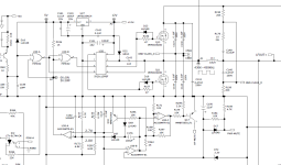
I wanted to know if anyone can help me with a Rockford Punch 60.2 trans.ana, I would need the diagram to know what model of diode is fitted on d2 and d3 as well as to be able to repair it 🙂
I wanted to know if anyone can help me with a Rockford Punch 60.2 trans.ana, I would need the diagram to know what model of diode is fitted on d2 and d3 as well as to be able to repair it 🙂
WTB Denon RC-123 remote
Hello,
I'm looking for a working RC-123 remote for my Denon PRA-1500 preamp.
Thanks
Damien
I'm looking for a working RC-123 remote for my Denon PRA-1500 preamp.
Thanks
Damien
Art Djpre II Modifications
- By chd_diy
- Analogue Source
- 20 Replies
I just finished a few modifications on my Art Djpre II, and thought I'd share them with the DIY community.
The first thing I changed was the power supply.
Many owners of this unit report that it sounds much better on battery power, or as reported in this post it can sound just as nice with a good quality regulated supply.
Cheap upgrade for Art DJ Pre ii owners : vinyl
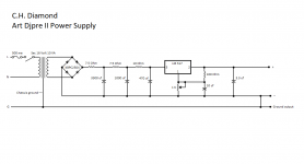
I looked at the one they suggested from Parts Express, but given that it is made by Mean Well, who to my knowledge only makes switching type supplies (which would introduce a lot of switching noise) I chose instead to build my own ripple filtered & regulated supply.
The original wall wart was 9VAC, which is rectified inside the chassis with small SMD diodes in a full wave bridge configuration.
The first filter cap is a 470uf, immediately after which the voltage is regulated down to 5VDC.
Since battery power improves the sound so much, my assumption is that everything after the regulator is of sufficient quality that little improvement could be made from there on.
So, I saw the 470uf cap as a good place to start.
The original is made by Junfu.
They are generally considered low grade crap, so I began the hunt for something better, and decided after reading probably way too much about the subject that an Elna Silmic II would be a substantial upgrade.
The first change was to replace the first filter cap C5 with an Elna Silmic II 470uf @ 25V.
The Elna is slightly larger than the original, but did fit with a slight bend in the leads.
The power supply I came up with is pretty straight forward, and has a nice clean output.
It should be adjusted to 12VDC.
I was a bit skeptical of the difference these changes would make, but listening tests confirmed what others have noticed.
Quieter, more dynamic, improved depth & clarity.
I could have quit at that point, but then I had another small thing to work out.
I am using the Djpre II with an Ortofon 2M Blue.
The inductance of this cartridge is rated at 700mh, which I confirmed measures 728mh with an inductance meter.
With the capacitance of the tonearm cable, interconnects, and the Djpre II internal loading capacitance of 100pf, I was getting a resonant peak at roughly 11.4khz give or take, which was readily apparent in listening tests.
This page has a calculator to estimate resonant peaking with various capacitance loads, and explains really well the effects of changing the cartridge load.
Hagerman Technology LLC: Cartridge Loading
So, it seemed pretty clear that I needed to shed every pf I could to get closer to ideal frequency response from this cartridge.
I tried low capacitance cables, which helped a bit, but it still wasn't low enough capacitance to get rid of that resonant peak within my hearing range.
I briefly considered going with a lower inductance cartridge like a Grado, but where's the fun in that?
I contacted ART and asked for a schematic, but they said that they no longer provide schematics for their current line of products, because they have had some of their designs stolen by other companies.
Since I was only looking to tune the input capacitance, I really didn't need the entire schematic, so I contacted them again and described my problem, and what I was trying to do.
The ART QC engineer consulted the Design engineer who both shared their knowledge of this circuit and helped me to get rid of that last 100pf load capacitance, which in turn got rid of the resonant peak (at least to my ears).
I would like to thank both of them for their help.
It was much appreciated.
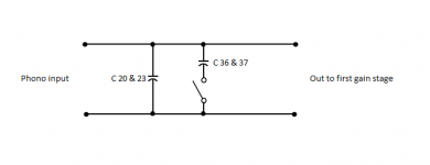
So, here it is.
C20 & C23 are the 100pf cartridge load capacitors.
They stay across the input all the time.
C36 & C37 are both 100pf capacitors which are switched in parallel with the fixed capacitors (C20 & C23) to achieve 200pf loading.
Removing C20 & C23 gives you 0pf load on the 100pf setting, and 100pf load on the 200pf setting.
It's as simple as that.
Without giving away any of their trade secrets, I made the overly simplified schematic of the input loading circuit as a way to visualize the effect of removing C20 & C23.
The first thing I changed was the power supply.
Many owners of this unit report that it sounds much better on battery power, or as reported in this post it can sound just as nice with a good quality regulated supply.
Cheap upgrade for Art DJ Pre ii owners : vinyl
I looked at the one they suggested from Parts Express, but given that it is made by Mean Well, who to my knowledge only makes switching type supplies (which would introduce a lot of switching noise) I chose instead to build my own ripple filtered & regulated supply.
The original wall wart was 9VAC, which is rectified inside the chassis with small SMD diodes in a full wave bridge configuration.
The first filter cap is a 470uf, immediately after which the voltage is regulated down to 5VDC.
Since battery power improves the sound so much, my assumption is that everything after the regulator is of sufficient quality that little improvement could be made from there on.
So, I saw the 470uf cap as a good place to start.
The original is made by Junfu.
They are generally considered low grade crap, so I began the hunt for something better, and decided after reading probably way too much about the subject that an Elna Silmic II would be a substantial upgrade.
The first change was to replace the first filter cap C5 with an Elna Silmic II 470uf @ 25V.
The Elna is slightly larger than the original, but did fit with a slight bend in the leads.
The power supply I came up with is pretty straight forward, and has a nice clean output.
It should be adjusted to 12VDC.
I was a bit skeptical of the difference these changes would make, but listening tests confirmed what others have noticed.
Quieter, more dynamic, improved depth & clarity.
I could have quit at that point, but then I had another small thing to work out.
I am using the Djpre II with an Ortofon 2M Blue.
The inductance of this cartridge is rated at 700mh, which I confirmed measures 728mh with an inductance meter.
With the capacitance of the tonearm cable, interconnects, and the Djpre II internal loading capacitance of 100pf, I was getting a resonant peak at roughly 11.4khz give or take, which was readily apparent in listening tests.
This page has a calculator to estimate resonant peaking with various capacitance loads, and explains really well the effects of changing the cartridge load.
Hagerman Technology LLC: Cartridge Loading
So, it seemed pretty clear that I needed to shed every pf I could to get closer to ideal frequency response from this cartridge.
I tried low capacitance cables, which helped a bit, but it still wasn't low enough capacitance to get rid of that resonant peak within my hearing range.
I briefly considered going with a lower inductance cartridge like a Grado, but where's the fun in that?
I contacted ART and asked for a schematic, but they said that they no longer provide schematics for their current line of products, because they have had some of their designs stolen by other companies.
Since I was only looking to tune the input capacitance, I really didn't need the entire schematic, so I contacted them again and described my problem, and what I was trying to do.
The ART QC engineer consulted the Design engineer who both shared their knowledge of this circuit and helped me to get rid of that last 100pf load capacitance, which in turn got rid of the resonant peak (at least to my ears).
I would like to thank both of them for their help.
It was much appreciated.
So, here it is.
C20 & C23 are the 100pf cartridge load capacitors.
They stay across the input all the time.
C36 & C37 are both 100pf capacitors which are switched in parallel with the fixed capacitors (C20 & C23) to achieve 200pf loading.
Removing C20 & C23 gives you 0pf load on the 100pf setting, and 100pf load on the 200pf setting.
It's as simple as that.
Without giving away any of their trade secrets, I made the overly simplified schematic of the input loading circuit as a way to visualize the effect of removing C20 & C23.
Attachments
Cube Audio FC8 speaker build help
- Construction Tips
- 4 Replies
Hello everyone,
I want to build this (plan below) bass reflex cabinet for the Cube Audio FC8 driver. This is my first attempt and I have some questions.
1. Are there any acoustic downsides to screwing the back panel in place so access to the interior can be maintained ?
2. There is a label on the side elevation drawing which says "This section might be filled with sand". What are the pros and cons of doing so, and what would be the process for filling / removing the sand ?
3. I have an oak floor which is laid on concrete. What sort of speaker feet would be best ?
Thanks in advance for any help,
Mark
Thoughts on a unique OB setup
Login to view embedded media
Login to view embedded media

Front and rear coaxial 8"s (from JBL 328CT) on a sideless enclosure as shown- I'm currently running it as a front/back dipole (coaxes out of phase front and rear) but it's designed to allow for a "dipole/bipole" configuration where cancellation will be more like a pair of traditional open baffles firing front and rear. They are set up on top of subs rather than on the floor (as shown).
Dipole cancellation's pretty straightforward, either the "inside" of drivers cancel and the front and rear have an effective baffle width of the baffle width plus 1" (Added waveguide effective depth) plus 7.5" (1/2 the total system depth between baffles)
When run as "bipole dipole" effective baffle width is simply Baffle Width + .75 (1/2 of the 1.5" thick baffle) +1" (Added Waveguide effective depth)
I haven't had a chance to measure in the current setup, but I'm currently crossing at 140hz, which is probably an overly aggressive high-pass (could probably be lower), but I'd love to hear any thoughts people have on such a setup.
The coaxes are normally ceiling mounted with a shallow waveguide, my waveguide is somewhat improved, in that it closely tracks the cone profile and is slightly larger, deeper, and smoother than the JBL ceiling mount metal waveguide. This is important as the horn leverages the cone as the waveguide so that transition must be as smooth as possible.
I'd love to hear any thoughts- this is an experimenter system, regardless of the (rather ridiculous) effort required to create the waveguide. Naturally I have my own ideas for what might work in this highly configurable system, but I figure this is the best place for such conversations.
Login to view embedded media
Front and rear coaxial 8"s (from JBL 328CT) on a sideless enclosure as shown- I'm currently running it as a front/back dipole (coaxes out of phase front and rear) but it's designed to allow for a "dipole/bipole" configuration where cancellation will be more like a pair of traditional open baffles firing front and rear. They are set up on top of subs rather than on the floor (as shown).
Dipole cancellation's pretty straightforward, either the "inside" of drivers cancel and the front and rear have an effective baffle width of the baffle width plus 1" (Added waveguide effective depth) plus 7.5" (1/2 the total system depth between baffles)
When run as "bipole dipole" effective baffle width is simply Baffle Width + .75 (1/2 of the 1.5" thick baffle) +1" (Added Waveguide effective depth)
I haven't had a chance to measure in the current setup, but I'm currently crossing at 140hz, which is probably an overly aggressive high-pass (could probably be lower), but I'd love to hear any thoughts people have on such a setup.
The coaxes are normally ceiling mounted with a shallow waveguide, my waveguide is somewhat improved, in that it closely tracks the cone profile and is slightly larger, deeper, and smoother than the JBL ceiling mount metal waveguide. This is important as the horn leverages the cone as the waveguide so that transition must be as smooth as possible.
I'd love to hear any thoughts- this is an experimenter system, regardless of the (rather ridiculous) effort required to create the waveguide. Naturally I have my own ideas for what might work in this highly configurable system, but I figure this is the best place for such conversations.
Diy Store...
- By motosapien
- Pass Labs
- 0 Replies
They must be busy as beavers putting kits together ( we hope ). Be nice if they offered a 90+ spl desktop speaker kit. Maybe just a baffle routed out for the drivers? That seems to be the missing piece.
6E5P Microphony
- Tubes / Valves
- 25 Replies
I've been working on a single ended parafeed headphone amp that I've had for the better part of the past decade. Every few years I take it apart to try something new. Most recently, I converted it from 6S45Ps to 6E5Ps and can't seem to dial these new tubes in.
I've attached the schematic of the amp section and a photo of the amp. The power supply uses a big SumR toroid followed by a 6BY5 rectifier and LC filter (5H + 420uF MKP). The raw supply is shunt regulated. The regulator is a simple IXYS DMOS CCS with no cascode set to 120mA. The shunt leg is a high voltage MOSFET with 3 0C3 glow tubes spanning from the drain to gate to generate a 330V regulated B+ supply. All tubes are heated with AC, with the rectifier tube and signal tube on different windings.
The amp section is quite simple. The 6E5P has about 4V on the cathode and is biased to 30mA with a CCS on the plate. There's a 2k grid stopper, 10R on each cathode pin, 100R on g2, and I've experimented with plate stoppers but ended up taking them out. The tubes are on teflon sockets which mount directly to a small PCB, and the stoppers are 0603 thin film resistors that are physically no more than 2mm from their respective pins.
The issue I'm hearing is really strange. Certain notes seem to excite a microphonic resonance in the tubes right around 3.5k. As the volume is increased, the intensity and duration of the ringing inreases, too. Hi-hats just sound miserable.
I had a couple of hypotheses: either the tubes were oscillating at RF, making them more prone to microphonic ringing, or there's some junk sneaking in through the power supply. Here's a partial list of things I tried.

And here's the noise floor, with input transformers, taken before running the FR sweep. Note the peak at 3.5k and the rise in the noise floor centered around 7k. This measurement was also taken with 20k grid stoppers, and the rise at 7k was much higher with 2k in place.

I know the tube is well liked here. Any thougts on how I can get them to sound good?
I've attached the schematic of the amp section and a photo of the amp. The power supply uses a big SumR toroid followed by a 6BY5 rectifier and LC filter (5H + 420uF MKP). The raw supply is shunt regulated. The regulator is a simple IXYS DMOS CCS with no cascode set to 120mA. The shunt leg is a high voltage MOSFET with 3 0C3 glow tubes spanning from the drain to gate to generate a 330V regulated B+ supply. All tubes are heated with AC, with the rectifier tube and signal tube on different windings.
The amp section is quite simple. The 6E5P has about 4V on the cathode and is biased to 30mA with a CCS on the plate. There's a 2k grid stopper, 10R on each cathode pin, 100R on g2, and I've experimented with plate stoppers but ended up taking them out. The tubes are on teflon sockets which mount directly to a small PCB, and the stoppers are 0603 thin film resistors that are physically no more than 2mm from their respective pins.
The issue I'm hearing is really strange. Certain notes seem to excite a microphonic resonance in the tubes right around 3.5k. As the volume is increased, the intensity and duration of the ringing inreases, too. Hi-hats just sound miserable.
I had a couple of hypotheses: either the tubes were oscillating at RF, making them more prone to microphonic ringing, or there's some junk sneaking in through the power supply. Here's a partial list of things I tried.
- Increasing all stoppers and adding plate stoppers. Bumping up the grid stopper to 20K helped just a bit, but now I don't manage 20kHz bandwidth.
- Converting the power supply to an LCRCRC, or a cLCRCRC where the first C is about 100nF. Currently, the three caps are in parallel with no Rs, and no small input cap.
- Elevating the 6E5P heaters to 50V (surprisingly, didn't impact 60Hz noise at all)
- Starving the 6E5P heaters to 6V to reduce gm
- Redoing all the ground wiring
- Changing the bias current from 40mA to 30mA per tube to reduce gm
- Adding input transformers
- Adding an EMI filter on the RCA input connectors
- Adding an EMI filter on the IEC power connector
- Trying out 6 different 6E5Ps, two different manufacturer stamps with different date codes. These all rang within a few 100Hz of each other.
- Adding a ground loop breaker between the circuit ground and IEC earth
- Removing the power supply regulator entirely
- Measuring with the inputs shorted (gave slightly lower noise than with RCA cables)
- Switching between a standard parafeed connection (primary returning to ground) and a WE parafeed connection (primary returning to cathode)
And here's the noise floor, with input transformers, taken before running the FR sweep. Note the peak at 3.5k and the rise in the noise floor centered around 7k. This measurement was also taken with 20k grid stoppers, and the rise at 7k was much higher with 2k in place.
I know the tube is well liked here. Any thougts on how I can get them to sound good?
Attachments
Crown SA/PSA-2
- By dieseldude
- Solid State
- 0 Replies
I see these have been off the radar for awhile. I'm about to dive into a SA I have that has been out of action for too long. The last round a few years ago found some of the gold plated small transistor legs broke down. And had under the gold plating literally turned to dust. Causing them easily rip loose. Since then I have acquired a PSA parts unit so I'm headed back in. I've already worked thru the output modules and they are now up to spec. So the only known issue is the main motherboard which is the location of these transistors. This doesn't seem to be an issue with them all. So perhaps it's due to some past environmental exposure.
Nevertheless any recent service advice would be appreciated.
Many thanks in advance,
DD
Nevertheless any recent service advice would be appreciated.
Many thanks in advance,
DD
WTB 2 x Inductors for PeeCeeBee V5 Amp
I need 2, WELL MADE, 2.0UH coils spec'd for the new V5 version of the PeeCeeBee amp boards.
PM me with details.
Rick
PM me with details.
Rick
USB soundcard for Linux
Anyone know of a usb soundcard that works fine i Linux.USB for my Laptop.
Around 100$
Around 100$
Soundstream Rubicon 502 with DC voltage in right channel
- By tonedeak99
- Car Audio
- 244 Replies
Hi everyone. Was hoping to get some help diagnosing and hopefully fixing this amp. The amp blew a vintage MB Quart speaker. Very sad about that since it was one of my favorite speakers but that's another story. I checked the voltage on the right speaker terminal and it has 30v DC. From my research, it seems to be a bad output transistor. Any help will be greatly appreciated.
Can't connect to QCC3008
- By Horson
- Digital Line Level
- 19 Replies
I've got a couple of QCC3008 modules that I just can't connect to via SPI (I keep getting an 'error detecting chip type' message in the WIN1.0.167 version of PSTool) and I'm wondering if its because they have the later type bluetooth module on them rather than the older BTM308-C. My USB to SPI interface is working fine on the older modules (8630), I've tried connecting SPI_En directly to 1V8 and 3V3 via a resistor. I can't even change the firmware as Blueflash doesn't recognise the chip.

This is the older type

This is the later ones I've got.
I was just wondering if anybody had had success connecting to these later type modules as in the Youtube video series from Dariee, he uses the older type and I can't find anything out about the later modules.
Many thanks.
This is the older type
This is the later ones I've got.
I was just wondering if anybody had had success connecting to these later type modules as in the Youtube video series from Dariee, he uses the older type and I can't find anything out about the later modules.
Many thanks.
Tweeter position on front baffle
- Multi-Way
- 2 Replies
I am planning to build a pair of 2 way bookshelf speakers. I have seen in some speakers that the tweeter is not aligned with the center of the front baffle. I understand that this is supposed to help with diffraction. Is positioning the tweeter closer to one side a straight forward benefit (while keeping it as close to the midwoofer as possible), or does it require other considerations to be worth it?
Akai AJ480fS
- By Logic7247
- Solid State
- 4 Replies
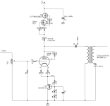
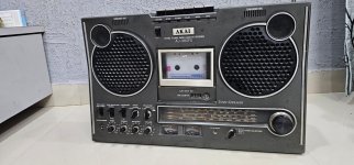
Dear all o have an akai AJ480fs tape recorder with 4 band radio .I bought it from a vintage collector .unfortunately the radio not working kindly help me with schematic diagram or some ideas .The radio Circuit is a bit confusing with its power supply.
A 220mf electrolytic cap is connected with 220 ohm resistor from a zener diode connected from 12 volt dc through 100ohm resistor the zener is grounded .but the +ve and -ve terminals of the cap is shorted with looping ground of mainboard .so when ever I am connect all cables across the cap no dc bias .when I checking with meter it's shows grounded .all the caps are tested ok
Kindly help
🙏
Attachments
Matching transistor input stage, am I doing it right?
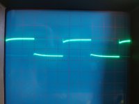
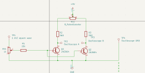
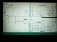
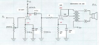
After a lot of reading about how to match transistor for the differential input stage in a amp, I came across this video which makes sense to me. So a constructed the circuit, but substitute the matched resistor with a multi turn pot instead. Also I used my old Wavetek signalgenterator for the square wave. After some tweaking with the oscilloscope I got it working. Had to use grandpas old analog scope though, cause my digital was way to noisy. I plugged in channel A at collector of one transistor and channel B at the other one, then subtracted B from A, to make the scope show the difference between them both.
The circuit seems to be working as it should. It takes about half minute or so for the current to stabilize after I change transistors. Toughing the transistor with my finger (of course I use tweezers) make the curves go way of. Attached are to pics with one properly matched pair I think, the other one not so good. Resolution is 2 mV per square.
My question is what is exactly I am measuring, Vbe of hfe? Or both? Seriously I am not shore. The transistor under test are close to saturation but there yet not, so hfe should matter. But since there is not a separeta and identical voltage source for the base, Vbe should affect the base current. Or, I am not sure...
Attachments

Eschewing Bluetooth?
- By motosapien
- Digital Source
- 8 Replies
Years ago I bought a Schiit Modi dac so I could play out of my computer directly. But BT seems to have improved greatly over the years. The BT on my Emotiva is quite good. Do any of you avoid BT preferring a DAC?
Intermittent 5600 Hz buzz
- Analog Line Level
- 2 Replies
I recently finished a simple stereo tube drive stage with tube regulated power supply. Aside from a 56hz hum (grounding I assume) it has a consistent periodic pop at 560 hz, and a regular (on ~10 seconds, off 10 seconds) digital buzz/ whine at 5600 hz. Any ideas? I tried different tubes but same result.
Xsim error question
- By profiguy
- Software Tools
- 2 Replies
I was trying to set up an xover sim in Xsim and get this error trying to input component values. It happens in every field. Anyone have a clue whats causing this?
Attachments
Old Samson RS12 PA Speakers with Hexagon-shaped Pole Mounts?
- By rayb70
- PA Systems
- 2 Replies
Hello, I have a pair of older RS12 PA Speakers from Samson. They are about 20 years old. The manual says they can "be stand mounted via their standard 1 3/8-inch speaker stand receptacles". I purchased Samson LS50P speaker stands which have standard 1 3/8" pole adapters, which are round, like a cylinder. The RS12 speakers have hexagon-shaped pole mount holes. The posts fit in the holes, but are tight and a bit difficult to disconnect. Here is a photo of the pole mounts:

Am I doing this correctly or are there different pole adapters for the hexagon-shaped holes? I looked and I see no mention of adapters like this, but maybe they are just too old?
I contacted Samson, but the answer I received seemed a bit lacking. They said "It must be very old. The new units are very different. I don't think you are doing anything wrong. It should be tight, but not too tight."
Does anyone know if this is just the way it is and that I am not doing anything wrong?
I appreciate any info. I'm just a hobbyist, but wanted to get this correct.
Thanks.
Impact of gauge on inductors
- Parts
- 2 Replies
Hi all.
What sort of considerations need to be made with swapping one inductor for another in terms of gauge? I would like to replace a 0.3 mH 18 AWG inductor with a 0.3 mH 15 AWG inductor. The reason for the switch is that I want to try the Jantzen Audio litz wire inductor (https://www.parts-express.com/Jantz...itz-Wire-Air-Core-Inductor-255-908?quantity=1). Would it pose any issues to swap out the air core inductor (https://www.parts-express.com/Jantzen-1313-0.30mH-18-AWG-Air-Core-Inductor-255-218?quantity=1) for the litz wire inductor?
Thanks!
For Sale Free Hook Up Wire Part I for pickup in San Diego area
Hey there, you know how it is, reorganizing and want to get rid of a LOT of wire and also how about some heat shrink for you.
Pickup in San Diego area- Miramar Road off the 15.
Most all the wire is silver-teflon MIL spec ranges from say 24-12 AWG.
The pictures are accurate but looking at them... there is more than you think in those spools and boxes.
This is FREE to whoever wants it, in support of your DIY efforts.
Just post here that you want some or all of it so I know to check my email, which is-
"john1in2" and "at symbol" yahoo.com (just don't want to put in an email link for harvesting).
Also if you are chatty- chat me up! I have other diy stuff that I could give away or sell- capacitors, chassis, etc... lets see what you are into and what you need as I have stopped building after filling up a room of equipment.
Box 01- some spools in here are copper but the bags are silver teflon (mostly)

Box 02

Spools 01, all MIL silver/teflon. the purple/white spool is very full.

Heat Shrink- I'll even throw in the heat gun for you. This is 1/4" red and 1/8 red and another 1/8 black non adhesive

Pickup in San Diego area- Miramar Road off the 15.
Most all the wire is silver-teflon MIL spec ranges from say 24-12 AWG.
The pictures are accurate but looking at them... there is more than you think in those spools and boxes.
This is FREE to whoever wants it, in support of your DIY efforts.
Just post here that you want some or all of it so I know to check my email, which is-
"john1in2" and "at symbol" yahoo.com (just don't want to put in an email link for harvesting).
Also if you are chatty- chat me up! I have other diy stuff that I could give away or sell- capacitors, chassis, etc... lets see what you are into and what you need as I have stopped building after filling up a room of equipment.
Box 01- some spools in here are copper but the bags are silver teflon (mostly)
Box 02
Spools 01, all MIL silver/teflon. the purple/white spool is very full.
Heat Shrink- I'll even throw in the heat gun for you. This is 1/4" red and 1/8 red and another 1/8 black non adhesive
Mackie SRM450 V2 repair
I'm trying to do an SRM450 v2 repair with blown Q11 AND Q12 but I'm having a hard time finding IRFB31N20D replacement MOSFETs that aren't fake. What is everyone using as a direct replacement for the MOSFET with a 47-ohm gate? Another component I'm having a hard time finding is a MOSFET gate pin Ferrite Bead, BOM part "MAG FERRITE BEAD 4X2X5.0MM W5". I've found a few forums referencing substitute but no one has confirmed if the subs work. Digikey is my go-to for parts.
Attachments
Linn Majic DS - PSU failure
- By Phonoblog
- Digital Source
- 12 Replies
I have a Linn Majik DS with Dynamic PSU which was suddenly dead last Sunday. It produced only a low volume sparking noise when repowering but the display remained dark.
I found on the Internet that a cap in the power supply causes this error, see here.
I opened my unit but unfortunately, I have a different PSU as seen below.
It has two of these suspicious caps but no obviously faulty element on the PCB.
Anyone out here knowing this problem and what component to replace?
Attachments
MosFET blows immediately after supplying power
Let me start off by saying my electronics repair experience is very limited. I don't have an oscilloscope that works (long story), so I'm only able to do simple diag with a DMM.
I have a Sundown SIA-2500D. Recently, one of the power supply mosfets (IRF-1404) blew up. Gate resistors measured okay, checked gate to source on all fets and they don't appear to be shorted. Visually everything else is okay. I replaced the blown one with a new one, gave power to the board, and it immediately blew a chunk right off the top of the package. I thought I would try replacing it one more time just in case it was a bad fet, and it popped again. I'm going to mess around with it a bit more to see if there's anything I can do, if not, I'll hand it over to a professional to take care of. I would appreciate any help in diagnosing.
I have a Sundown SIA-2500D. Recently, one of the power supply mosfets (IRF-1404) blew up. Gate resistors measured okay, checked gate to source on all fets and they don't appear to be shorted. Visually everything else is okay. I replaced the blown one with a new one, gave power to the board, and it immediately blew a chunk right off the top of the package. I thought I would try replacing it one more time just in case it was a bad fet, and it popped again. I'm going to mess around with it a bit more to see if there's anything I can do, if not, I'll hand it over to a professional to take care of. I would appreciate any help in diagnosing.
For Sale PCB´s for Lunddahl SUTs
Needed the SUT´s for other project, so here´s a pair of PCB´s for most Lunddahl SUT´s.
They are from Emission Labs, and have a bunch of connection possibilities, such as Variable load, Zobel,
fixed load, fixed cap, links for serial or parallel connection a.o.
25 Euro with untracked free shipping inside EU. Rest of the world.... Ask.
PayPal fam. & friends only in danish currency = 185,00 DKr.
Check my optoisolator mods?
- By cuibono
- Power Supplies
- 1 Replies
Maybe this isn't the right forum, if not, mods please move 😀
I'm modifying a commercial roaster. The hardware is good, but the control software is not. I'm in process of modifying the circuit board to accept standard third party control hardware and software. I believe what I'm doing is relatively simple, but wanted to check with others.
I'd like to patch the new hardware's control signals in at two optoisolators (MOC3023) on the existing circuit boards. The issue is that the new hardware references earth ground, while the existing circuit board uses a floating ground. I've looked at the optoisolator data sheet (https://www.onsemi.com/pdf/datasheet/moc3023m-d.pdf) and it looks like I can simply cut the two optoisolators free from the floating ground, and then connect the signal-in and earth-referenced ground from the new hardware.
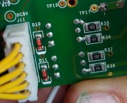
I've taken some pictures. The first picture shows the floating ground, highlighted in green. I've included a picture of the back side of the circuit board, showing what I believe are two clamping diodes on the inputs of the optoisolators. I want to cut the trace at the red line to separate the optoisolators from the floating ground. Should work? Any thoughts?
I'm modifying a commercial roaster. The hardware is good, but the control software is not. I'm in process of modifying the circuit board to accept standard third party control hardware and software. I believe what I'm doing is relatively simple, but wanted to check with others.
I'd like to patch the new hardware's control signals in at two optoisolators (MOC3023) on the existing circuit boards. The issue is that the new hardware references earth ground, while the existing circuit board uses a floating ground. I've looked at the optoisolator data sheet (https://www.onsemi.com/pdf/datasheet/moc3023m-d.pdf) and it looks like I can simply cut the two optoisolators free from the floating ground, and then connect the signal-in and earth-referenced ground from the new hardware.
I've taken some pictures. The first picture shows the floating ground, highlighted in green. I've included a picture of the back side of the circuit board, showing what I believe are two clamping diodes on the inputs of the optoisolators. I want to cut the trace at the red line to separate the optoisolators from the floating ground. Should work? Any thoughts?
Attachments

Hifonics BXE1250.1D without audio
Hello friends, I am looking to solve this problem. It is a hifonics BXE1250.1D amplifier, initially the problem was in the power supply and it was solved, but now in the output I have oscillation and voltages of +-15v in operational amplifiers and still apparently no audio signal arrives which appears to be an irs2010s, but when I touched parts of the pre-amplification I managed to see audio at the output of the amplifier, I already changed some operational amplifiers and I couldn't get it to work beforehand, I appreciate your support and send greetings to the group
Attachments

Soundcraft si performer 1
- Parts
- 0 Replies
Can someone give me the part number for the slide faders on the soundcraft si performer 1
The Runt - A nice little SE EL84 amp.
- By dubadub
- Tubes / Valves
- 6 Replies
Greetings, Friends. I wanted to share my progress on the little SE EL84 amp I've been playing with.

It's undergone a host of changes since my last update. I've installed a pair of 10w 3.5k OPTs, rewired the output tubes for Triode mode, and rewired the driver stage to mirror @Suncalc 's Marblewood Amp. In fact, I seem to have arrived at an EL84 version of that design. Per the EL84 datasheet, a pair of EL84 wired in triode with a 270ohm Kr will pull 2x 36mA = 72mA. Trying to be frugal as the PT only is rated for 104mA.

And the power supply

obligatory gut shot - Large Orange Caps!

As expected, the smaller OPTs deliver less bass than the 15W, but the amp has such a delightful clarity through the upper range that I don't miss it. I had an afternoon of Joe Pass records that really made me fall in love with the amp. Rewiring the driver stage to the "Universal 4S Preamp" made a huge improvement, thanks Matt for posting such wonderful designs!
It's undergone a host of changes since my last update. I've installed a pair of 10w 3.5k OPTs, rewired the output tubes for Triode mode, and rewired the driver stage to mirror @Suncalc 's Marblewood Amp. In fact, I seem to have arrived at an EL84 version of that design. Per the EL84 datasheet, a pair of EL84 wired in triode with a 270ohm Kr will pull 2x 36mA = 72mA. Trying to be frugal as the PT only is rated for 104mA.
And the power supply
obligatory gut shot - Large Orange Caps!
As expected, the smaller OPTs deliver less bass than the 15W, but the amp has such a delightful clarity through the upper range that I don't miss it. I had an afternoon of Joe Pass records that really made me fall in love with the amp. Rewiring the driver stage to the "Universal 4S Preamp" made a huge improvement, thanks Matt for posting such wonderful designs!
Attachments
Eric Carmen RIP
- By levistubby
- Music
- 0 Replies
Eric Carmen died last weekend at age 74.
https://www.msn.com/en-gb/entertain...r&cvid=49006706bf0447d0ac3d9b6d4ee991cb&ei=24
https://www.msn.com/en-gb/entertain...r&cvid=49006706bf0447d0ac3d9b6d4ee991cb&ei=24
PF86
- By gorgon53
- Tubes / Valves
- 4 Replies
It just occured to me that the PF86 instead of a EF86 migth be a better choice for a low level preamp because the 300mA heater could be fed with constant dc current easely obtainable from 6.3Vac (the needed ca. 4,5V at the heater would leave nice headroom for regulation ). Did any of you use the PF86 instead of of the EF86?
Four ASUS Essence STXii, one clock
I have four ASUS Essence STXii soundcards I would like to clock together. On my Linux machine.
Does anyone know of a good way to do that?
I've read that clocking can be achieved via SPDIF connections, the original STX had a SPDIF connector for connecting with video cards, it makes sense that if the STXii also has the same connector in the same place it does the same thing, and that it could be used for clocking...
https://www.overclockersclub.com/reviews/asus_xonar_essence_stx/2.htm
"The last two connectors on the card are a 4-pin "Molex" power connector and a S/PDIF header."
That's the best I've been able to find so far, anyone have any ideas?
Rockford 500BD old design
This amp came in with a shorted toroid, vented C59 and vented C17.
I replaced all defective parts and upon power up the cap C59 immediately vents. C17 cap did not. It is installed correctly, I double checked.
I removed C59 again and checked the pads for voltage.
+ 13.57 on pos pad
- 0.957 on neg pad
The original cap for C59 was 100uf 25v. I installed a 100uf 50v and powered the amp and it did not vent.
I checked the pads with the cap installed and am getting +46vdc on the postive lead and the same reading on the negative lead as before.
This cap is tied directly to Q13 LM317 positive regulator. The in voltage on pin 3 of the regulator is obviously also 46vdc.
D6 and D8 also have the 46vdc on the cathode end.
I am confused as to where this 46vdc is coming from. It does explain why the 25v cap was venting, but not 100% sure how its getting there.
Luxman re-capping - Nichicon KG caps Type I, II, III - which one for audio amp
- By gwiazd0r
- Solid State
- 9 Replies
Hi,
Does anybody have experiance with large power capacitors.
Im restoring an old Luxman amplifier and need to replace old 10,000uF 50V capacitors. I cant tell what original once type is !!
I have checked sheets and there are three types I , II and III
Anybody has experiance to advise which Type to use ?
BTW, the Type I is most expensive
https://www.hificollective.co.uk/sites/default/files/2023-07/Nichicon KG series data sheet.pdf
Are my tubes going gassy?
- By toshiba_nz
- Tubes / Valves
- 8 Replies
So I got these 1940's tubes in what seemed unused appearance ...I started them off slowly, applied DC heater gently for a few hours, then brought the filaments up to rated voltage (DC) for 6 hours. Then applied B+ and grid voltage at 75% of max dispersion for ~6 hrs.
However, after using the tubes within spec for a week, I've noticed a slight change in appearance - a very slight whitish appearance on some areas of the glass (close to the getter) , where there was crystal clear glass previously.
Should I be worried?
However, after using the tubes within spec for a week, I've noticed a slight change in appearance - a very slight whitish appearance on some areas of the glass (close to the getter) , where there was crystal clear glass previously.
Should I be worried?
Vinyl turntable technology transfer technical support
- Vendor's Bazaar
- 5 Replies
At present, the sales of vinyl records are getting better and better around the world. We have accumulated a number of vinyl turntable production technologies, which can help you quickly master the design plan and production process, and can independently produce high-end vinyl turntables in a short time.
The technologies we currently possess include: magnetic levitation turntable bearing technology, air suspension turntable bearing technology, motor control technology, voltage-stabilizing silent air pump technology, and vinyl turntable complete machine design and production technology.
Currently, the retail price of a single brand vinyl turntable using the above technology can reach US$5,000-20,000 on the market.
If anyone is interested in vinyl turntable production, we can provide technical support.
The specific technology transfer price can be customized according to the type of technology you need.
Our email address: cengruyue@gmail.com
Welcome to contact us!
Attached to the video is a magnetic levitation turntable bearing designed by us
Login to view embedded media
Attached to the video is a video of the air suspension turntable we made
Login to view embedded media
Attached to the video is a playback video of a recently produced magnetic levitation turntable.
Login to view embedded media
Our email address: cengruyue@gmail.com
Welcome to contact us!
Need Schematics for Monster Power MPA 2250
- By rd48sec
- Solid State
- 1 Replies
I am working on a Monster Power MPA 2250 where the left channel is not working. I would really like to find a schematic. Can anyone help with that?
Thanks!!
-Joel
Thanks!!
-Joel
MSB Link DAC from the 90’s - Help!
- By Imago
- Digital Source
- 14 Replies
Well, I stumbled across this the other day and thought I’d make a little stereo system for a friend with a disability.
Trouble is, I can ‘t find the power supply which is likely a big wall wart, or I never had one to begin with.
What are the odds of someone having one, or helping me build one? Looks like a 6 pin DIN.
I hate to throw things out…
Trouble is, I can ‘t find the power supply which is likely a big wall wart, or I never had one to begin with.
What are the odds of someone having one, or helping me build one? Looks like a 6 pin DIN.
I hate to throw things out…
Attachments
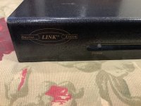
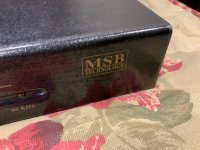
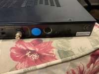
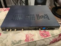
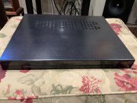
Sonics 800x Popping Sounds
- By Nvphotos
- Solid State
- 1 Replies
I have two Sonixs 800x amplifiers that have some pretty bad behavior (significant pops and crackles) on startup and shutdown. I've had two separate speakers now that I've had a scare with from these amplifiers after I had thought they were safe to use.
Could it be as simple as a light switch in line with the speaker wire to disconnect the speakers when I turn each amplifier on and off?
Could it be as simple as a light switch in line with the speaker wire to disconnect the speakers when I turn each amplifier on and off?
Giveaway: Semisouth pair and Pearl 3 boards
The other day I was exchanging emails with one of our forum’s great members, Bob @flocchini. He mentioned having some SJEP120R100 not being used, and would I like to facilitate a giveaway? Yesterday I received Bob’s tracer-matched SJEP pair, so let’s do this! For my part, I’m including a pair of assembled Pearl 3 boards for a second winner.
Giveaway:
Rules and conditions:
One entry per person (obvious, but worth saying). We’ll pick both winners from the same list, so no need to create two lists. I'll pay for the shipping. As long as USPS will ship to your country/address, you meet the criteria.
How it'll work:
To enter, just copy the list of entrants, paste into a new comment, add your DIYA username to the bottom of that list and post. In 48 hours or so, I'll make a comment saying that entries are closed. I'll take the final list of entrants, paste them into an online randomizer, and the name that appears in the top (#1) position will be the winner of the SJEP pair. The person at the very bottom of the list will receive the Pearl 3 boards. From there, winners simply need to PM me their mailing address and I'll get them posted.
Giveaway:
- 1 pair SJEP120R100
- 1 pair of populated and tested Pearl 3 boards
Rules and conditions:
One entry per person (obvious, but worth saying). We’ll pick both winners from the same list, so no need to create two lists. I'll pay for the shipping. As long as USPS will ship to your country/address, you meet the criteria.
How it'll work:
To enter, just copy the list of entrants, paste into a new comment, add your DIYA username to the bottom of that list and post. In 48 hours or so, I'll make a comment saying that entries are closed. I'll take the final list of entrants, paste them into an online randomizer, and the name that appears in the top (#1) position will be the winner of the SJEP pair. The person at the very bottom of the list will receive the Pearl 3 boards. From there, winners simply need to PM me their mailing address and I'll get them posted.
Attachments
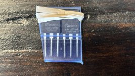
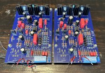
Back here after a long hiatus
And want to get back to building the Aleph clone (using BrianGT green boards)
But alas, have forgotten much and will lean on this community for help getting started back.
Regards,
Vinay
But alas, have forgotten much and will lean on this community for help getting started back.
Regards,
Vinay
For Sale JLH Phono Shunt feedback PCB's (new old stock)
- By jamesfeline
- Swap Meet
- 2 Replies
Hello
I now have some surplus JLH phono shunt feedback PCB's for sale (new old stock) that I purchased originally some time ago
asking £20 each plus postage ( 4 boards are available) I am UK based and would like payment by PayPal
happy to get a postage quote before I post please note one PCB will make a stereo preamp .. plus will provide construction manual via email if needed.
eBay find, kiss, marry, kill
- By Vermouth
- Full Range
- 11 Replies
I managed to get a selection of drivers on eBay, I bought them mainly for the Alpair 7.3.
So what would you build, keep or sell (kiss, marry, kill)
Fostex FE126En
Fostex FF 85WKeN enabled by @planet10
Scanspeak 10F/8424G00
Mark Audio Alpair 7.3
So what would you build, keep or sell (kiss, marry, kill)
Fostex FE126En
Fostex FF 85WKeN enabled by @planet10
Scanspeak 10F/8424G00
Mark Audio Alpair 7.3
Order out of chaos.
- The Lounge
- 1 Replies
Over the last 10 years I have been building and selling all sorts of electronic pcb's and systems.
It started off with a couple of sets of drawers for components.
I now have the drawers plus about 6 cardboard boxes full of components.
As it has grown incrementally I know exactly which component is in which box.
To add to the confusion I have about one square foot left on the bench to work in.
It started off with a couple of sets of drawers for components.
I now have the drawers plus about 6 cardboard boxes full of components.
As it has grown incrementally I know exactly which component is in which box.
To add to the confusion I have about one square foot left on the bench to work in.
A Simple Discrete Current-Mirror IV Converter, à la AD844
- By EUVL
- Digital Line Level
- 51 Replies
.
This was supposed to be a private project, and I was not planning to publish.
But it is amazing to see people still talking about the AD844 as IV.
That is even though Pedja has published a very similar but discrete circuit quite some 15 years ago.
https://www.diyaudio.com/archive/bl...-out-production-pedja-rogic-ddnf-iv-stage.pdf
The problem with the AD844 is that it lacks bias.
The -Vin node has a Zin of 50 ohm, which implies a bias of about 0.25mA.
Using a 0.25mA-biased push-pull input to convey (say) 1mA current signal can only mean that it has to work in Class AB,
i.e. no longer push-pull as long as signal is > -6dBFS.
And yes, you can improve this by stacking 4x or 8x AD844s.
But it is a clumsy and no-longer-elegant solution, apart from expensive.
Just for fun, we did something more similar to a discrete-but-simplified AD844 than Pedja’s.
It has a bias of 2mA, i.e. equal to 8x AD844 in parallel.
Performance is not comparable to the CEN IV, but it uses fixed rails and has an integrated emitter follower buffer.
Bandwidth & distortion were measured with 2mApp DAC current (e.g. PCM1704), and Riv is 2.8k for 2Vrms output.
For the likes of PCM1796, you can increase bias to 3mA and it will couple with 4mApp without much loss in performance.
For more DAC current, you will have to stack as well, or use through hole components for even higher bias.
We want to use SMD because you can get really-low-noise Toshiba dual BJTs that are easy obtainiums.
And they are monolithic, ie. perfect for thermal tracking.
A lot more fun than stacking AD844’s. 🙂
Patrick
.
Attachments
Need advice to start my first electronic project
- By Os2033
- Equipment & Tools
- 18 Replies
Hi, I have some basic training in electronics and I am looking to start my first project (improve a vintage CD player) toward DIY audio but I am on a very tight budget. Here are the tools I have in mind so far
HP Agilent DSO3062A Oscilloscope, 60 MHz, 1 GS/s, 2 Channel ~130CAD
Weller wad 101 digital soldering station ~100CAD
Do you think I can do better with the price list above for each tool? What else do I need to start a project?
Thanks in advance.
Oscar
P.S. I also accept used equipment since all tools I list above are price for used as well.
Anyone ever done a fixed tone stack voicing circuit?
- By jjasniew
- Instruments and Amps
- 0 Replies
In a Mesa Maverick, one channel has a fixed tone stack, of the usual Fender design. The other channel has B,M,T panel controls in a similar stack topology.
Anyone ever done this as a basic "voicing" design ingredient?

Perhaps imparts a generic eq similar to this;

Anyone ever done this as a basic "voicing" design ingredient?
Perhaps imparts a generic eq similar to this;
Marantz CDA-94
- By donf
- Digital Line Level
- 7 Replies
Hello,
I have a Marantz CDA-94 lurking in a corner of the workshop that might be worth selling. I've never used such a thing in my stereo system but received one from a client of mine. It needs testing so I'll be hooking it up to an old Meridan 208 to see if it at least works. Cosmetically, it has a few scratches on the wooden sides and a slight nick at the top of its front metal face. Internally it looks fine.
From initial searches in the Internet it appears that this D/A has had a good reputation in the past with at least one restorer adding improved power supply filtering and replacing the existing Philips D/A chip with a better version of the same (two-crown chip). The build is certainly solid, to say the least.
I have two questions:
1) Is there still an interest in this model and is it worth putting on the market at all?
2) Having no optical link in the workshop I am left with using a coax interconnect. For basic testing, is it reasonable to connect the coax digital output of the Meridian 208 to the digital tape input of the Marantz CDA-94? (I seem to be unable to get the user's manual)
I would be grateful for comments/suggestions
donf
Heathkit IO-18 oscilloscope, worth repairing or scavange parts?
- By Mayday
- Equipment & Tools
- 12 Replies
Hi,
I've had two heathkit devices that where gifted to Me some years ago. One IO-17 and one IM-18.
I decided to see if they worked today, and the IM-18 jumped to life after I don't know how many years, sadly the IO-17 didn't as far as I could tell.
I'd expected the small crt to light up if it worked.
The schematics was easy enough to find. I haven't found manuals for them, yet.
Anyway, is there any point in repairing the old oscilloscope (I don't have one) or should I just remove transformer etc from it and then scrap it?
What rating PSU do i need for full range EQ board
Hello,
What rating psu is needed for this, i was looking at this from Mouser:
709-RPS30-24
Thanks
What rating psu is needed for this, i was looking at this from Mouser:
709-RPS30-24
Thanks
My F4 adventure begins
I am going to finally make a jump and start building the my first diyaudio project. I am going to build the F4, but as I have read it is not just a simple plug and play amplifier. I'm gonna need a pre-amp.
Looking in the store I have came up with a few options.
Can I have good advice on a choice please. One which will happily feed the F4. From what I have read the pre-amp for the F4 is going to be the defining part in the overall sound of this amplifier so I do want to take great care in getting it right first time.
Advice on another pre-amp is welcome or why these are a bad idea.
Looking in the store I have came up with a few options.
- The AC pre-amp
- Maybe a full ACA could work?
- The Whammy
Can I have good advice on a choice please. One which will happily feed the F4. From what I have read the pre-amp for the F4 is going to be the defining part in the overall sound of this amplifier so I do want to take great care in getting it right first time.
Advice on another pre-amp is welcome or why these are a bad idea.
Simulating a Speaker (and it's frequency Response) in Python
- By audiomoose
- Software Tools
- 14 Replies
Hello all,
I am trying to figure out how to simulate a speaker in python.
My basic understanding of this topic is that I should use the Thiele-Small Parameter to calculate values of an electrical network which represents the Speaker (electrical and mechanical part).
Then this network needs to be expressed as an function so we can use it to generate the output for a given input. For example a simple sine wave should show up with some harmonic distortion at the output.
As I am not a scientist, I have no idea how to calculate the values of the electrical network and I couldn't find a good source on the internet that explains it so I can understand it. I hope (and think) that it should be relatively easy to calculate those values from the Thiele-Small-Paramters once you have the right formulars at hand. If someone could point them out to me that would be a great help for making this first step.
For Sale Pass Labs XP-10
Something’s got to give, so this goes up for sale. Nice condition and just came back from PL (remote control repair) with a new double box. I would call it “neutral” sounding…somewhere in between a BA3-FE and a ZM Balanced Iron Pre, but not much like my tube preamp. $2000 plus shipping (N America only) to a member of diyAudio. It will go up on US AudioMart in one week for more $$.
Attachments
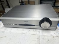
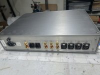

About beta-enhancing emitter-follower buffer between the input stage and the VAS
- By gaetan8888
- Solid State
- 39 Replies
Hello
I allway hesitated to use beta-enhancing emitter-follower buffer between the input stage and the VAS, because of it's reputation to be unstable,
Is it true that it's unstable ?
Thank
Bye
Gaetan
I allway hesitated to use beta-enhancing emitter-follower buffer between the input stage and the VAS, because of it's reputation to be unstable,
Is it true that it's unstable ?
Thank
Bye
Gaetan
Attachments
For Sale UK: Troels Gravesen Speakers ScanSpeak Discovery-3WC-MkII in Baltic Birch Enclosure
Troels Gravesen Speakers ScanSpeak Discovery-3WC-mkII in a baltic birch multiply enclosure (surface so far unfinished).
Detailed info about the speaker available on Troel's hompage troelsgravesen.dk
GBP 599 (for the pair) for self-collectors in the UK (or plus fuel cost if I deliver and you don't live too far away from Milton Keynes).
These speakers wwere built from a kit from Jantzen Audio in Denmark (level 2 crossover parts).
The enclosure has been built from baltic birch 18mm. The surface is so far unfinished and the buyer can decide if they just want to put lacqeur on top or a veneer.
Comes with the original instructions from Troels.
Scanspeak drivers are
D2608/913000 tweeter
15W/8434G00 mid range
22W/8534G00 woofer
The crossover is built from parts of that Jantzen kit. The upgraded binding posts are the components that did not come with the kit.
I also have applied L-pads for the mid and high range, but you can unplug those if you like the original sound better.
because of the weight and fragile nature I cannot ship these speakers via post.
Collection in Milton Keynes is an option, I also can deliver by car within a range of 200 miles around Milton Keynes (at fuel cost).
For Sale Bridged RB-TA3020-3 1.2kW Tripath evaluation board
- By brunomiguel
- Swap Meet
- 11 Replies
RB-TB TA-3020 1.2Kw class T amplifier for sale 160€
Genuine working Tripath evaluation pcb board with heatsinks mounting screws not supplied.
Tracked shipment to European union
Skematics sended together with articles.
Payment by PP
If you enjoy this kind of stuff check my stuff related:
https://www.ebay.de/usr/dialedinmusic?_trksid=p4429486.m3561.l2559
Attachments
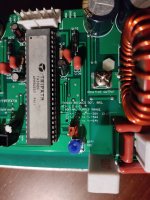
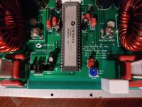
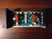
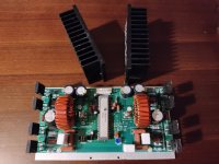
I need help with identifying a resistor (R53) from a Kicker CXA600.5
I need help with identifying a resistor (R53) from a Kicker CXA600.5
I fix amps as a hobby and got this Kicker CXA600.5 for free and do believe this missing resistor is the problem.
I traced the remote circuit and it lead me to R53. If anyone has a schematic and willing to share, I will be so thankful.
Thanks
Jean

I fix amps as a hobby and got this Kicker CXA600.5 for free and do believe this missing resistor is the problem.
I traced the remote circuit and it lead me to R53. If anyone has a schematic and willing to share, I will be so thankful.
Thanks
Jean
SAE 2600
- By Bob 123
- Solid State
- 1 Replies
Does anyone know if an SAE 2600 form Japan can have it's transformer wired for 120volt operation?
Which PA - Band needs help!
- PA Systems
- 17 Replies
Hi Guys. Apologies If this in the wrong section I'm new here 👋
I run a party function band for weddings and corporate events. It's a 5 piece band & consists of Drums, bass guitar, keys, electric guitar and a lead vocal (keys and drums do backing vocals) we do events of around 250 - 350 people. Would be great if there were speakers that could do 250 -500 people in the price range but not expecting miracles.
I recently bought the Yamaha DBR 15 tops and after two weddings and two separate sound engineers telling me they are not loud enough. I caved and sold them.
So now I am after some new speakers that are louder. I've seen the Alto TS415's at about £380 per speaker and claiming 2000 watts. Are these any good? Or are there better speakers available for the money. I say right now I have a budget of £5/600 PER speaker to play with.
We don't currently use a sub, but will be looking to add one at some point ( no idea when ) so need some that can cater to the events we do for now with just tops.
I've tried to look into RMS and watts and some speakers are louder with less power ect but it's just too techy for me! Lol
All advice appreciated
Thanks
WTB Toshiba MosFETs
I would like to buy a set of Toshiba MosFet for BA-3 preamp w/o spending $$$.
I have a new set of Kimber Kable PBJ 3' interconnects I would trade or sell to fund the MosFet purchase.
In Michigan USA.
Thanks
I have a new set of Kimber Kable PBJ 3' interconnects I would trade or sell to fund the MosFet purchase.
In Michigan USA.
Thanks
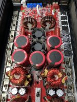
Audax A652
Hello all
I have all the drivers for the Audax A 652 designed by the famous Vance Dickason. It's been a long time and I want to know if it is really good enough to spend the time and effort building it.
I have all the drivers for the Audax A 652 designed by the famous Vance Dickason. It's been a long time and I want to know if it is really good enough to spend the time and effort building it.
Audio-Technica’s Tube Headphone Amplifier for $108,000
- By FritzS
- Everything Else
- 17 Replies
Audio-Technica’s Tube Headphone Amplifier for $108,000 - Is this price still normal?
Use four Takatsuki 300B power tubes, ECC83S gold pin small-signal tubes, amorphous-core silver-wire Lundahl input and output transformers, dual-mono configuration and a fully-balanced drive design.
What do DIY tube specialists say about this?
Audio-Technica’s $108,000 Tube Headphone Amplifier Must be Heard at CanJam NYC 2024
https://www.ecoustics.com/products/audio-technica-narukami/
For Sale Hagerman Clarinet preamp
SOLD
Greetings! I have a Hagerman Clarinet preamplifier for sale. Sold originally as a kit, I purchased it from the builder some years ago. I used it in my main system for a good long while. Sounds great, holographic, smooth yet well detailed mids and highs. It sports 3 inputs and two outputs. In fine condition. Didn't think I'd let it go but I want to go a different direction with my system.
Will come with a pair of Amperex 12AU7's, and a Phillips 5Y3GT rectifier tube. The rectifier has a fancy Herbie's Audio Lab tube damper installed, which I will include.
It was a stock build when I picked it up. I did upgrade it with Sonicaps where appropriate. I also performed a mod that was endorsed by Jim Hagerman that further improves the sound by reducing the noise floor. This mod is detailed here - https://www.audiocircle.com/index.php?topic=75735.0
$425 shipped to conus. You may notice in one of the pics that transformer wires are disconnected, this has to be done to remove top cover (which I did to service it). Wires were then reconnected, unit was tested.
Attachments
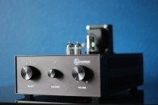
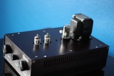

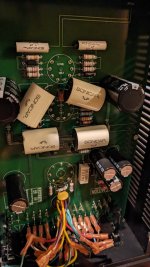
What is the purpose of supplying the AC to rectifier through capacitors
- By Bas Horneman
- Power Supplies
- 33 Replies
Like in the encircled part of the schematic.

High WAF Dynamic Speaker System Build
Hi,
This is a build thread of a speaker system for my living room built on the unitized image wavguide design from Patrick Bateman: https://www.diyaudio.com/community/threads/unitized-image-control-waveguide.319698/page-16
The waveguide being used is constant directivity and offers about 360Hz-20khz range at 96db/w/m using 4 midranges and one tweeter. I went off this design because one of the best speakers I ever heard were the Lambda Acoustic Unity's (licensed from Tom Danley). They did everything right, so this design has similar performance in a smaller waveguide.

- I need the bass cabinet to be dynamic, loud, crisp and have a wide sweet spot. My musical tastes are all over the place, rock, fusion, synthwave, jazz, etc.. Metal is the most demanding as it needs to have crisp kicks and snare along with the wide bandwidth of the rest of the instruments. To find out what freqeuncies need special attention, I took a spectrum analysis of a demanding track "God's Equation" by Pagans Mind as shown below:

As you can see, a substantial amount of musical energy is focused in between about 350hz to 40hz. Kick drums range in 40 to about 100Hz, snare peaks around 193hz, with activity up to around 425hz. Toms focus around 105 to 158hz. This explains why I always liked a higher crossover frquency in my car and never liked the 80hz, it crosses over in the middle of the kick drum. The good news as the around 300 - 400 hz, there seems to be less peaks for various types of msuic of that style, so a crossover can go right there.
- The speakers need to fit both sides of the fireplace in these areas for the WAF to be high (Wife Acceptance Factor) and would be disguised to look like a radiator (like on the left) or a cabinet of some sort. I have a space of up to about 32" long x 18"deep x 25"high. It could be up to 30" if the design has to use that height. The idea is to have the horn sit in it's own box on the top, which brings it to about 30" anyway.

That being said, these are the constraints and objectives:
1. Bass bin that covers 40hz to 400hz,
2. High sensitivity around 97+ db/w/m. Why? I don't know why, but for some reason big speakers sound more dynamic, even at lower volume levels despite the math showing the same output level.
3. Fit within an area of up to about 32" long x 18"deep x 25"high (81cm x 45cm x 64cm). That a volume of 8-10 cu. ft (235L - 283L) Must be box-shaped, this will look like a cabinet or radiator cover with paint and "creativity".
4. MiniDSP, FIR filters, Active Filters are all ok for the bass cabinet. The waveguide would ideally remain passive.
5. The waveguide and be a part of the cabinet or separate.
6. I am knowledgeable in work working to cut and glue panels.
7. sound dynamic at both lower and high volume levels. I typically listen around 85db-90db. I don't plan on blasting concert levels, but want the option.
8. I am open to any and all ideas to achieve the objectives above, breaking conventional rules is ok. 🙂
Some ideas that I have been thinking about for a while:
I'll be going over some simulations to see what may be possible. I would greatly appreciate anyone's input - any and every suggestion would be greatly appreciated!
This is a build thread of a speaker system for my living room built on the unitized image wavguide design from Patrick Bateman: https://www.diyaudio.com/community/threads/unitized-image-control-waveguide.319698/page-16
The waveguide being used is constant directivity and offers about 360Hz-20khz range at 96db/w/m using 4 midranges and one tweeter. I went off this design because one of the best speakers I ever heard were the Lambda Acoustic Unity's (licensed from Tom Danley). They did everything right, so this design has similar performance in a smaller waveguide.
- I need the bass cabinet to be dynamic, loud, crisp and have a wide sweet spot. My musical tastes are all over the place, rock, fusion, synthwave, jazz, etc.. Metal is the most demanding as it needs to have crisp kicks and snare along with the wide bandwidth of the rest of the instruments. To find out what freqeuncies need special attention, I took a spectrum analysis of a demanding track "God's Equation" by Pagans Mind as shown below:
As you can see, a substantial amount of musical energy is focused in between about 350hz to 40hz. Kick drums range in 40 to about 100Hz, snare peaks around 193hz, with activity up to around 425hz. Toms focus around 105 to 158hz. This explains why I always liked a higher crossover frquency in my car and never liked the 80hz, it crosses over in the middle of the kick drum. The good news as the around 300 - 400 hz, there seems to be less peaks for various types of msuic of that style, so a crossover can go right there.
- The speakers need to fit both sides of the fireplace in these areas for the WAF to be high (Wife Acceptance Factor) and would be disguised to look like a radiator (like on the left) or a cabinet of some sort. I have a space of up to about 32" long x 18"deep x 25"high. It could be up to 30" if the design has to use that height. The idea is to have the horn sit in it's own box on the top, which brings it to about 30" anyway.
That being said, these are the constraints and objectives:
1. Bass bin that covers 40hz to 400hz,
2. High sensitivity around 97+ db/w/m. Why? I don't know why, but for some reason big speakers sound more dynamic, even at lower volume levels despite the math showing the same output level.
3. Fit within an area of up to about 32" long x 18"deep x 25"high (81cm x 45cm x 64cm). That a volume of 8-10 cu. ft (235L - 283L) Must be box-shaped, this will look like a cabinet or radiator cover with paint and "creativity".
4. MiniDSP, FIR filters, Active Filters are all ok for the bass cabinet. The waveguide would ideally remain passive.
5. The waveguide and be a part of the cabinet or separate.
6. I am knowledgeable in work working to cut and glue panels.
7. sound dynamic at both lower and high volume levels. I typically listen around 85db-90db. I don't plan on blasting concert levels, but want the option.
8. I am open to any and all ideas to achieve the objectives above, breaking conventional rules is ok. 🙂
Some ideas that I have been thinking about for a while:
- Open baffle with two SB Audience Bianco-15OB350 15" Open Baffle Woofers per side. Maximum distance I can keep drivers from wall (at the baffle) would be 18". *I have tried this approach about 12 years ago with early 15" Acoustic elegance dipole woofers on sale. I remember good clean bass with one 15" woofer, so much that it occurred a single one woofer would have been ok, even being close to a wall. That was the "rule breaker" concept as it had the best bass I ever heard in terms of quality. I don't remember regarding dynamics. I had used DSp at the time with a Behringer feedback destroyer unit.
- Sealed cabinet with a 6ft. space using a single SB Audience Bianco-15OB350 15" Open Baffle Woofer Joseph Crower had good success with this, as it showed good promised with critical damping. https://josephcrowe.com/blogs/news/...y-15-2-way-monitor-using-sb-audience-products I was thinking adding resonant chambers inside to damp the impedance peaks like the Hegeman enclosure design from this thread: https://www.diyaudio.com/community/threads/3d-printed-metamaterials.360739/page-5
- Front loaded horn similar to the University Classic, but would need to be reshaped to fit the 18" depth, not sure this is practical for 40hz-400hz. Maybe something like William Cowan's Horn Sub Jr., but with a side scoop to make it front firing: https://www.cowanaudio.com/hornsubjr.html
- Karlsonator / Karlson cabinet of some sort. Freddi speaks highly of these cabinets, but it would need to lay on it's side. They don't simulate well, but I hear lots of praises for it's sound.
- Front loaded bass refelx like Altec A7, but not so large. Joseph Crowes awesome 1798 cabinet looks VERY promising to work off of, but it's too big for my space. However, maybe squashed down/ isobaric loading and with Onken Style vents / passive radiators could do it in the volume I have to work with: https://josephcrowe.com/blogs/news/bass-cabinet-no-1798 I could integrate the waveguide into the top part of the woofer horn.
- Slot Loaded open baffle, or slot loaded closed - Brings down distortion, but concerned with frequency response about 250hz (maybe not an issue?).
- Something Wild and Different - Hybrid Front loaded horn with tapped horn aka Cyclops style tapped horn? 6th/8th order band pass? Front loaded Horn with woofer feeding a Paraline lens that goes into a conical horn?
I'll be going over some simulations to see what may be possible. I would greatly appreciate anyone's input - any and every suggestion would be greatly appreciated!
Load more
Projects by fanatics, for fanatics
Get answers and advice for everyone wanting to learn the art of audio.
Join the Community
507,909
Members
7,893,306
Messages