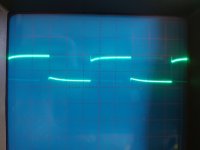
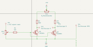
After a lot of reading about how to match transistor for the differential input stage in a amp, I came across this video which makes sense to me. So a constructed the circuit, but substitute the matched resistor with a multi turn pot instead. Also I used my old Wavetek signalgenterator for the square wave. After some tweaking with the oscilloscope I got it working. Had to use grandpas old analog scope though, cause my digital was way to noisy. I plugged in channel A at collector of one transistor and channel B at the other one, then subtracted B from A, to make the scope show the difference between them both.
The circuit seems to be working as it should. It takes about half minute or so for the current to stabilize after I change transistors. Toughing the transistor with my finger (of course I use tweezers) make the curves go way of. Attached are to pics with one properly matched pair I think, the other one not so good. Resolution is 2 mV per square.
My question is what is exactly I am measuring, Vbe of hfe? Or both? Seriously I am not shore. The transistor under test are close to saturation but there yet not, so hfe should matter. But since there is not a separeta and identical voltage source for the base, Vbe should affect the base current. Or, I am not sure...
Attachments

Well, more equal. But not identical, I guess it will still be determined by the Vbe of the transistors. So how would this benefit?
The base currents are not forced to be the same, so the betas cannot be compared.
For a differential stage you need a current source for the emitters.
Or a resistor going to a negative DC voltage.
Right now the the transistors are turning on and off, so the hfe cannot be compared.
Press the flat faces of the transistors together and fasten with a tie to thermally couple them.
For a differential stage you need a current source for the emitters.
Or a resistor going to a negative DC voltage.
Right now the the transistors are turning on and off, so the hfe cannot be compared.
Press the flat faces of the transistors together and fasten with a tie to thermally couple them.
I designed a transistor matching jig years (decades) ago and gave it to this community. I think you can find it in an Adcom GFA565 thread near the end. Several have built it with success and a few boards have been designed. You can get sub 1% matches this way. You do have to tie the two transistors together (foam cap works) and block air currents (box works). You have to give it time to thermally stabilize.
Basically, both transistors must be at the same temperature exactly to be matched. That is requirement #1. I used precision resistors in each collector and made a diff pair circuit using a CCS as the tail current generator. Just measure between the collectors for the best null value (it will be less than a mV). I found 2 to 3 mA a good compromise, but the jig I made has several values ranging from 100uA to 6 mA or more.
I do measure higher DC drift stability and lower distortion with close matched pairs, so theory matches practical reality. SOme people can readily hear the difference (= measured reduction in distortion).
-Chris
Yes, my second prototype. I still use it in fact.
Note the LED in the pass transistor hole. That is to thermally couple those two devices. There is foam between the transistor and PCB to further enhance the thermal coupling between the LED and transistor. It makes the tail current adjustment less variable with temperature. The jumpers are to set tail current, you could just use a couple, or make it fixed at one current. The collector resistors are 0.1% dale with low TC, the base resistors are 10K 0.1% low TC as well. That allows you to measure beta at that current level (1/2 the tail current for a balanced pair).
The capacitors on the PCB are not critical, they are only there to prevent oscillation.
-Chris
Very interesting reading, your circuit seems very well engineered. I think I understand how it works now (can't open diptrace files, but found a eagle schematic in some other post). A few questions though;
- What supply voltage did you use?
- The transistor for the CCS could be BD139/DB140, I guess?
- Why not use a trimmer isntead of the high precision resistor as I did?
- What supply voltage did you use?
- The transistor for the CCS could be BD139/DB140, I guess?
- Why not use a trimmer isntead of the high precision resistor as I did?
Thank you. I made the first on perf board because I realised measuring beta separately wasn't that useful. I needed something immediately and came up with the concept. I still have it, but it kind of fell apart from use. That's why I put it on a PCB, and I wore a few of those out too! Anyway, the concept was solid and I made only a couple of improvements. What you see is very, very close to what is sitting here built on perf board.
I use about 11 VDC bipolar, you can use a pair of 9V batteries. It isn't too critical, I tried to keep V C-E around 10 VDC as in the datasheets for signal transistors.
Yes, those will work fine. I try to use high hFE parts. TO-126 package so a 3mm low efficiency LED will fit in the hole. A touch of thermal compound may help temperature tracking. We just want to make the current source stable, it doesn't buy you anything to make it rock steady, this only has a very slow drift until it stabilises, so more than sufficient for our needs. Maybe even too good!
Trimmers get noisy and may shift. You are passing the tail current through the contacts. So it was easy to use a few resistors and either DIP switches (did that in the next, works well) or the jumpers. One less thing to worry about. That and I don't want to measure to set the tail current, just set it and go. You could use a four position. I mostly see 100uA, 500uA, 1 mA and 3 mA. The switches/jumpers will combine resistors in parallel to give you more selections. I wouldn't use trimmers simply because I know how much I use this thing, and how many years it will be in service.
-Chris
Well you sure had a good answers answer. Good point with the voltage, didn't thought of that. Sorry for not replying sooner, work has been crazy lately. However you got quite convinced already, so today I bought some 0,1% tolerance resistor (already got the rest of the parts) and built the NPN version at perfboard. Got it working and the results were quite interesting. Most of the pairs I matched with the other circuit did not much very well anymore. Some of them did (within 1 mV), but most of them tested like 5-10 mV difference. Read in some other thread that about 1 mV or so was considered a good match I think.
So except that I miss the look of the analog oscilloscope I think your circuit makes more sense. Also that it test the gain, which was my intention in the first place. Think I read in "Audio amplifier construction manual" by R. Slone that transistor in differential input stages should be beta match.
Were did you put the capactiors in the circuit? Did not include them in my version as you can see.
Attachments

Hi, thanks!
Transistors are extremely temperature sensitive. Therefore they must be at the same temperature to be matched - just as they are in properly laid out PCBs. So if you can't hold the parts at the exact same temperature, you cannot get a match. This also means you need to allow time for temperatures to equalize between the transistors. You will often see the measurement rising and falling due to the parts finding a thermal equilibrium. Anyway, you have to let things settle down before taking a measurement. That's a pain as far as I'm concerned!
So mount the parts in physical contact, place a foam hood over the pair. Then place some container over the entire shooting match to block air currents. That will stabilize everything.
Nope, doesn't look very whiz-bang. Your meter merely becomes a null indicating device, but if you want to figure out degree of match you must be able to measure to three or more decimal places at 1 mV FS. That means a mighty good meter. I used HP 34401A's, then bought the new 34465A and 34461A. Most hand helds simply are not good enough at a few mV to be useful for determining degree of mismatch. You really only want the lowest readings and you're good to go.
The capacitors go across the supply at the input, I'll have to check the PCB. At one point I used them around the CCS transistors but found that wasn't necessary. I think I simply used the others across the supply at the other end of the board to keep RF impedance low. Those were low value, like 100nF - not critical.
-Chris
Community I have been trying different matching scenarios. First I am only a hobbyist so I see something build it and then test/try it out. I have the music from outer space set up right now and have tested 2n3904, 2n5550, 2n3440, 2n2222a. I am using the tl071 and ten volts like discussed on the MFOS website. I have confirmed I have 100ua running thru the set up. I actually surprised myself that with my limited knowledge I can see the difference while testing. I even built a spreadsheet that helps run the matches. I have no idea how accurate the set is and every transistor never reaches the .6V Vbe threshold. I get voltages of .585, .534, .525, .590, .566 volts. How can these reading be so low? I think there is something wrong, either not enough base current or collector current. I was testing these as if they would be used in differential pairs. I believe 100ua is too low, when testing. I know that in my Hafler amp the LTP current source is 1.3 to 1.6ma. I need a community expert to say if my thinking is correct. If my thinking is correct what resistors will give me the magical 1.6 or so ma current? I tried the Fritz set up also. Thanks for any explanation or help.
Hi Marksd,
You can measure and match transistors at 100 uA or even 50 uA, however I have always recommended you match the parts at the tail current (or close) to what they will be operating at.
Who the heck is Fritz? Maybe you should be asking him if you are following his method.
Otherwise your solution is simple. Read the thread, I have been very consistent throughout and any other time this subject comes up. What I came up with comes from theory and also practical experience and has worked for decades on the bench under actual working conditions in various designs of equipment. The jig I designed ages ago allows you to measure base-emitter drops (although this was never an intended feature), and voltage drops across base and collector emitters so you could figure out the beta if desired. However it is even easier. All you need to do is hange a sensitive enough meter between the collector test points. A perfect match would read 0.0000 mV but would vary as each device varies in temperature. The closer you are to 0 mV, the closer your match is. It is that simple.
-Chris
- What is the "MFOS website" for starters?
- Secondly, I'm not about to discuss what goes on elsewhere on the web. It's pointless and the context won't be there.
- Those readings look like base-emitter voltage drops. That is not how you match transistors. It also tells me you have not read or understood anything I have written - ever.
You can measure and match transistors at 100 uA or even 50 uA, however I have always recommended you match the parts at the tail current (or close) to what they will be operating at.
Who the heck is Fritz? Maybe you should be asking him if you are following his method.
Otherwise your solution is simple. Read the thread, I have been very consistent throughout and any other time this subject comes up. What I came up with comes from theory and also practical experience and has worked for decades on the bench under actual working conditions in various designs of equipment. The jig I designed ages ago allows you to measure base-emitter drops (although this was never an intended feature), and voltage drops across base and collector emitters so you could figure out the beta if desired. However it is even easier. All you need to do is hange a sensitive enough meter between the collector test points. A perfect match would read 0.0000 mV but would vary as each device varies in temperature. The closer you are to 0 mV, the closer your match is. It is that simple.
-Chris
Chris, MFOS is a a website call music from outer space. These are Vbe measurements. The test set I use include an opamp and you are always comparing your test transistor to something like a 2n3904 for NPN. You are correct I have not read anything you have written. Except now I can search for your material, thank you for that piece of information. I am not an electrical engineer or educated in the electronics world. I see things on the internet and build them and try them out. I am a very basic hobbyiest.
Hi Mark T,
Thanks, sounds interesting ( I like that stuff).
Hi Marksd,
Okay, I have no clue as to what you are using and have never heard of this before. I guess it would have been helpful to have posted the design and how it is used in order to get meaningful responses. Most of us don't have the time to research things for you (I don't), so help us out when you can please.
Have a good read ...
After a lot of reading about how to match transistor for the differential input stage in a amp
matching in order to achieve what?
Hi bengtssk,
Sorry, I missed your post.
The capacitors go from the supply rails to common. They are only a precaution and the values are not terribly critical. They are only there to maintain a low supply impedance to the common point in case something decides it wants to oscillate. Even though we are operating parts with gain at open loop (no feedback) and there is no reason for them to oscillate, I took the precaution to cover any odd circumstance. Plus it is only good design practice. As you can see, layout is forgiving and it works.
What you have found is exactly why I built it. I was measuring beta and still having issues that pointed to input pair mismatch. I sat and thought about it and decided to simply install the parts in the same circuit they were intended for and see what I measured. Well guess what? Many "matched pairs" were not close enough. Thought about it more and decided to make the tail current variable to set points so I could explore behavior over a wide range - and match what I saw in some circuits. There are circuits where the tail current is only 100 uA, and some where it is about 4 mA, 1 and 2 mA are by far the most common. It was more complicated and I determined what things made a difference and what didn't. Those that didn't affect anything were removed from the design. So what you have there is the most simple and effective way to match transistors.
You can figure out the gain from measuring the DUT base and collector currents, but that wasn't my primary objective. You can place a resistor in the current source collector so you can directly measure total tail current and compare that with the base current. It will only be close for a well matched pair. If you place resistors in the emitters you may degenerate the pair and make it less sensitive. Since beta is sensitive to temperature, you may as well get your matched pairs and then measure beta of one in the normal way. That's close enough knowing it varies, the most important thing is the match between the transistors.
Hi ctrlx,
Matching the differential pair both lowers distortion and minimizes DC offset and thermal drift of same. If you are working with a poorly designed amplifier circuit, then other things may also have a large effect. You must keep that pair in thermal contact, isolating them from ambient temperature differentials and air currents helps as well. Doing this will maximize the benefits of having a matched diff pair.
Using a current source to supply tail current raises the CMRR of the diff pair, improving performance. If you look at some more advanced amplifiers in that area you will see other modifications that further improve performance, but it all revolves around making the diff pair stable and maximizing CMRR. These same things also increase open loop gain allowing more feedback to correct more of the rest of the non-linearities in the overall circuit.
- Home
- Design & Build
- Parts
- Matching transistor input stage, am I doing it right?