I've been working on a single ended parafeed headphone amp that I've had for the better part of the past decade. Every few years I take it apart to try something new. Most recently, I converted it from 6S45Ps to 6E5Ps and can't seem to dial these new tubes in.
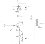
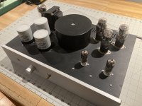
I've attached the schematic of the amp section and a photo of the amp. The power supply uses a big SumR toroid followed by a 6BY5 rectifier and LC filter (5H + 420uF MKP). The raw supply is shunt regulated. The regulator is a simple IXYS DMOS CCS with no cascode set to 120mA. The shunt leg is a high voltage MOSFET with 3 0C3 glow tubes spanning from the drain to gate to generate a 330V regulated B+ supply. All tubes are heated with AC, with the rectifier tube and signal tube on different windings.
The amp section is quite simple. The 6E5P has about 4V on the cathode and is biased to 30mA with a CCS on the plate. There's a 2k grid stopper, 10R on each cathode pin, 100R on g2, and I've experimented with plate stoppers but ended up taking them out. The tubes are on teflon sockets which mount directly to a small PCB, and the stoppers are 0603 thin film resistors that are physically no more than 2mm from their respective pins.
The issue I'm hearing is really strange. Certain notes seem to excite a microphonic resonance in the tubes right around 3.5k. As the volume is increased, the intensity and duration of the ringing inreases, too. Hi-hats just sound miserable.
I had a couple of hypotheses: either the tubes were oscillating at RF, making them more prone to microphonic ringing, or there's some junk sneaking in through the power supply. Here's a partial list of things I tried.

And here's the noise floor, with input transformers, taken before running the FR sweep. Note the peak at 3.5k and the rise in the noise floor centered around 7k. This measurement was also taken with 20k grid stoppers, and the rise at 7k was much higher with 2k in place.

I know the tube is well liked here. Any thougts on how I can get them to sound good?
I've attached the schematic of the amp section and a photo of the amp. The power supply uses a big SumR toroid followed by a 6BY5 rectifier and LC filter (5H + 420uF MKP). The raw supply is shunt regulated. The regulator is a simple IXYS DMOS CCS with no cascode set to 120mA. The shunt leg is a high voltage MOSFET with 3 0C3 glow tubes spanning from the drain to gate to generate a 330V regulated B+ supply. All tubes are heated with AC, with the rectifier tube and signal tube on different windings.
The amp section is quite simple. The 6E5P has about 4V on the cathode and is biased to 30mA with a CCS on the plate. There's a 2k grid stopper, 10R on each cathode pin, 100R on g2, and I've experimented with plate stoppers but ended up taking them out. The tubes are on teflon sockets which mount directly to a small PCB, and the stoppers are 0603 thin film resistors that are physically no more than 2mm from their respective pins.
The issue I'm hearing is really strange. Certain notes seem to excite a microphonic resonance in the tubes right around 3.5k. As the volume is increased, the intensity and duration of the ringing inreases, too. Hi-hats just sound miserable.
I had a couple of hypotheses: either the tubes were oscillating at RF, making them more prone to microphonic ringing, or there's some junk sneaking in through the power supply. Here's a partial list of things I tried.
- Increasing all stoppers and adding plate stoppers. Bumping up the grid stopper to 20K helped just a bit, but now I don't manage 20kHz bandwidth.
- Converting the power supply to an LCRCRC, or a cLCRCRC where the first C is about 100nF. Currently, the three caps are in parallel with no Rs, and no small input cap.
- Elevating the 6E5P heaters to 50V (surprisingly, didn't impact 60Hz noise at all)
- Starving the 6E5P heaters to 6V to reduce gm
- Redoing all the ground wiring
- Changing the bias current from 40mA to 30mA per tube to reduce gm
- Adding input transformers
- Adding an EMI filter on the RCA input connectors
- Adding an EMI filter on the IEC power connector
- Trying out 6 different 6E5Ps, two different manufacturer stamps with different date codes. These all rang within a few 100Hz of each other.
- Adding a ground loop breaker between the circuit ground and IEC earth
- Removing the power supply regulator entirely
- Measuring with the inputs shorted (gave slightly lower noise than with RCA cables)
- Switching between a standard parafeed connection (primary returning to ground) and a WE parafeed connection (primary returning to cathode)
And here's the noise floor, with input transformers, taken before running the FR sweep. Note the peak at 3.5k and the rise in the noise floor centered around 7k. This measurement was also taken with 20k grid stoppers, and the rise at 7k was much higher with 2k in place.
I know the tube is well liked here. Any thougts on how I can get them to sound good?
Attachments
Last edited:
Why the SS in the cathode when you have a CCS in the anode? They might be fighting each other. Can you try replacing the cathode reg with a resistor and see what happens?
That's a very odd problem. I would say there is something oscillating at 3.5KHz but not the amp. It too high a Q for simply LC. Could it be your shunt regulator like the glow tubes with the mosfet capacitance. The other thing to try a a series resistor with the output coupling cap.

Not the cause of your problem, but . . .
There is no base stopper resistor on the bipolar, and no ferrite bead on the bipolar base lead.
There is no base stopper resistor on the bipolar, and no ferrite bead on the bipolar base lead.
Thanks all for the suggestions!
It's a voltage source, rather than a current source. I didn't want to run the LEDs at 30-40mA, so they are buffered with a PNP emitter follower. The SS circuit's impedance works out to just under an ohm, so it shouldn't fight with the CCS. This is similar to the SiC diode biasing that @mogliaa popularized.
I've had success with this circuit in the past but replaced it with an unbypassed resistor after reading you and @6A3sUMMER.

Red channel is with 50R in the cathode (100R per cathode pin). This biases the channel to +1.4V on the cathode instead of +4V. The blue channel is with the solid state circuit. There is an improvement that outpaces the reduction in gain, but it's decidedly still there. I don't think the SS circuit is the root cause, but I wouldn't mind digging some more. I am a bit concerned about the rising gain outside of the audio band with both of these now that I'm back to using a 2k grid stopper.
I like this idea. I was bypassing the glow tubes with a single 56nF cap that span the three tubes, which are in series. I removed this cap and didn't see any change in the measured noise or microphony. I also have a stash of glow tubes, and after rolling another set in, didn't see any change in the measured response.
The mosfet is a very low capacitance SiC part. Here's a link (C3M0280090D). With these changes, the glow tubes should see no more than a few hundred picofarads. I have a 22 ohm resistor in series with the FET gate that I can try bumping up just to be on the safe side.
The series resistors, either as a plate stopper, or in series with the cap, didn't seem to help.
Why the SS in the cathode when you have a CCS in the anode? They might be fighting each other. Can you try replacing the cathode reg with a resistor and see what happens?
It's a voltage source, rather than a current source. I didn't want to run the LEDs at 30-40mA, so they are buffered with a PNP emitter follower. The SS circuit's impedance works out to just under an ohm, so it shouldn't fight with the CCS. This is similar to the SiC diode biasing that @mogliaa popularized.
I've had success with this circuit in the past but replaced it with an unbypassed resistor after reading you and @6A3sUMMER.
Red channel is with 50R in the cathode (100R per cathode pin). This biases the channel to +1.4V on the cathode instead of +4V. The blue channel is with the solid state circuit. There is an improvement that outpaces the reduction in gain, but it's decidedly still there. I don't think the SS circuit is the root cause, but I wouldn't mind digging some more. I am a bit concerned about the rising gain outside of the audio band with both of these now that I'm back to using a 2k grid stopper.
Could it be your shunt regulator like the glow tubes with the mosfet capacitance. The other thing to try a a series resistor with the output coupling cap.
I like this idea. I was bypassing the glow tubes with a single 56nF cap that span the three tubes, which are in series. I removed this cap and didn't see any change in the measured noise or microphony. I also have a stash of glow tubes, and after rolling another set in, didn't see any change in the measured response.
The mosfet is a very low capacitance SiC part. Here's a link (C3M0280090D). With these changes, the glow tubes should see no more than a few hundred picofarads. I have a 22 ohm resistor in series with the FET gate that I can try bumping up just to be on the safe side.
The series resistors, either as a plate stopper, or in series with the cap, didn't seem to help.
What if you replace the pnp tr. and the two leds and the 470 ohm resistor with : 4.1v/30mA= 136 ohm resistor. Actually use a 200 ohm pot (Bourns 3299, or 3386). This way you have the added advantage of setting your plate voltage to 1/2 B+ by adjusting the 200 ohm pot. The plate current is set by CCS, adjusting the cathode pot would not change that.
You have no way of adjusting your plate voltage in your circuit. Also the leds current is only 1.2 mA.
I use 6E5P in my 300B amplifier. Rod Coleman shunt cascode circuit.
Art
You have no way of adjusting your plate voltage in your circuit. Also the leds current is only 1.2 mA.
I use 6E5P in my 300B amplifier. Rod Coleman shunt cascode circuit.
Art
Here's a photo. The amp has seen better days, right now it's a bit of a rat's nest.
I just removed the regulator entirely, so the three octal sockets in the back are not connected to anything. They were for the glow tubes. I'm listening to it now-- it's great, but some songs still make the tubes ring. I wouldn't be surprised if someone with a different music catalog didn't notice it at all.
The two blue boards are the plate load CCSs. The green boards mount directly to the 6E5Ps which are on teflon sockets.
I've also disconnected the volume pot. The input RCA goes into an EMI filter (1k + 330pF), into shielded mic cable to the 6E5P boards. I've tried tying the shield to different grounds and haven't noticed any difference, so right now the shield is floating.
The rotary switch next to the headphone jack is an impedance switch.
The small transformer inside the chassis for the 6E5P heaters. It's a 12V transformer, so the two heaters are in series, with the center tap tied to ground. I tried elevating the center tap but I can't say it changed anything.
I'd really rather not. One of the great things about this tube is the low rp. If memory serves, the plate resistance with an unbypassed cathode resistor become rp + Rk*mu, which takes rp from 1k to 4k. Bypassing 130 ohms needs a big cap, which I'd also rather not use unless I have to.
I tried replacing the solid state circuit with a resistor in post #5 and didn't fully resolve the issue, so I don't think that this is the root cause.
I just removed the regulator entirely, so the three octal sockets in the back are not connected to anything. They were for the glow tubes. I'm listening to it now-- it's great, but some songs still make the tubes ring. I wouldn't be surprised if someone with a different music catalog didn't notice it at all.
The two blue boards are the plate load CCSs. The green boards mount directly to the 6E5Ps which are on teflon sockets.
I've also disconnected the volume pot. The input RCA goes into an EMI filter (1k + 330pF), into shielded mic cable to the 6E5P boards. I've tried tying the shield to different grounds and haven't noticed any difference, so right now the shield is floating.
The rotary switch next to the headphone jack is an impedance switch.
The small transformer inside the chassis for the 6E5P heaters. It's a 12V transformer, so the two heaters are in series, with the center tap tied to ground. I tried elevating the center tap but I can't say it changed anything.
What if you replace the pnp tr. and the two leds and the 470 ohm resistor with : 4.1v/30mA= 136 ohm resistor.
I'd really rather not. One of the great things about this tube is the low rp. If memory serves, the plate resistance with an unbypassed cathode resistor become rp + Rk*mu, which takes rp from 1k to 4k. Bypassing 130 ohms needs a big cap, which I'd also rather not use unless I have to.
I tried replacing the solid state circuit with a resistor in post #5 and didn't fully resolve the issue, so I don't think that this is the root cause.
Attachments

Did you ever try to use a cathode or source follower between the plate of 6E5P and the transformer?
Art
Art
I would look at this from one more angle, I saw very similar behavior in the driver stages of my SE amps using D3A, including an intermittent tone around 4kHz - the problem was actually VHF oscillation and the tone appeared when the D3A started to oscillate. Ferrite beads on grid and filament lines and some handwound 5uH chokes wound on lossy ferrite on the plates solved the problem. (placed right at the plate pin) Circuit is hybrid mu-follower.
I gave this a shot. The grid and two cathode pins and grid each got a Fair-Rite 2512061027Y1. Are these a sensible choice? The plate got 6 turns of #26 wire on a junk box ferrite core. The solid state circuit is on both channels' cathodes.Ferrite beads on grid and filament lines and some handwound 5uH chokes wound on lossy ferrite on the plates solved the problem.
Measured below. Red is the ferrite channel, blue is the resistor stopper channel. Looks like a small step in the right direction--- much less noise between 10k and 20k, and a slightly lower amplitude ringing at 3.5k.
Next step would be some COG/NPO ceramic caps from cathode pins 4 and 9 to chassis GND with leads as short as possible (I use SMD) 0.01uF. You will get this. 😀
When I mentioned ferrites on the filament that is actually what I meant. 😀 I would use capacitors directly to GND on the cathode connections. The filament to cathode insulation is significantly capacitive and in the VHF may couple to the filament wiring.
It does not look like it really improved much as far as I can see. I found evidence of oscillation with AM/FM/SW portables in the past, of course today I have none. You can also make wire probes to use with a scope of sufficient bandwidth.
Solid State and Tubes can always mix together.
But sometimes you get Brownies,
And other times you get Swamp Mud.
I think the mix is even more complex, BJT, MOSFET, Tube
It looks like soon you are going to tame it completely.
Let us know how it sounds then.
But sometimes you get Brownies,
And other times you get Swamp Mud.
I think the mix is even more complex, BJT, MOSFET, Tube
It looks like soon you are going to tame it completely.
Let us know how it sounds then.
Thanks all for the encouragement and helpful suggestions. I implemented a few more of these recommendations.
It measures exactly as it did prior to these changes. 🙁 The switcher didn't even manage to make things worse.
I'm thinking the next step is to try a different type of high gm tube to see if the chassis is haunted.
- Heaters are now powered by DC. I made a constant current source using LM317s and use one per heater, with the other leg of the heater connected to ground. Raw DC is supplied by a switcher followed by a common mode filter and differential mode CRC filter.
- Added ferrites to the heater leads.
- 10nF C0G caps tie each end of the heater to signal ground. (chassis ground is centimeters away!)
It measures exactly as it did prior to these changes. 🙁 The switcher didn't even manage to make things worse.
I'm thinking the next step is to try a different type of high gm tube to see if the chassis is haunted.
Some comments.
You use the "wrong" output of cascode CCS.
The "low Z" output of CCS guaranteed much lower output impedance. It's most "immune" to the cathode resistance changing.
The cascode CCS stage does not require regulated power supply, the only criterion is the appropriate headroom (at least 30V greater B+, than output swing upper corner).
If you use CCS loaded stage, the LED is prefect in the cathode. If you want higher bias, series connected (if the current is high, paralleled series strings) LEDs even gives lower dynamic impedance, than BJT.
The CCS loaded 6E5P gain is enormous (near 30dB), so any mistake may generates excitement. It's also has very high bandwidth, so some restriction is necessary.
p.s.
Sample:
Last edited:
My gut feeling is that the output transformer is acting up. Just for debugging, can you disconnect the transformer, replace it with a load resistor, and measure again?
I still wonder if its external to your amp.
If not than maybe you have built a VHF squegging oscillator.
If not than maybe you have built a VHF squegging oscillator.
BTW 6E5P cathode pins 4,9 must to connect together with wire (as short as possible) under the socket, instead of 10R resistors.
These pins are the inner screen too, so AC grounding IMO is necessary.
Use AC blocking paralleled with cathode biasing part (100nF//100pF).

Are you sure, that filament is good?
Have you tried it with two serial connected 3V battery?
These pins are the inner screen too, so AC grounding IMO is necessary.
Use AC blocking paralleled with cathode biasing part (100nF//100pF).
Are you sure, that filament is good?
Have you tried it with two serial connected 3V battery?
- Home
- Amplifiers
- Tubes / Valves
- 6E5P Microphony