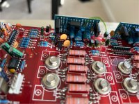
Hi everyone. Was hoping to get some help diagnosing and hopefully fixing this amp. The amp blew a vintage MB Quart speaker. Very sad about that since it was one of my favorite speakers but that's another story. I checked the voltage on the right speaker terminal and it has 30v DC. From my research, it seems to be a bad output transistor. Any help will be greatly appreciated.
It could be a shorted output. Did you check them (all of them) to see if any were shorted?
Confirm that all emitter resistors essentially read 0 ohms on your meter.
Confirm that all emitter resistors essentially read 0 ohms on your meter.
Hi Perry. I just watched this great video
on how to check the fets (see 17:18min). I'll check them later today. Where do I find the emitter resistors? Also does anyone have the schematics for this amp to share with me.
Thanks Perry. Q2, Q3, Q4, Q5 and Q6 are all shorted on the legs opposite the emitter resistor legs. All emitter resistors are within spec.
Shorted base to collector?
It's likely that only one is shorted. They are in parallel so if one appears shorted, all in parallel with it will as well.
Even if only one is shorted, you need to replace all in that group, preferably with transistors from the same production code/manufacturing date.
It's also possible that the driver transistor on the driver board is shorted. You may want to check that first (before removing the outputs).
Alright Perry. I have a bunch of questions. Sorry.
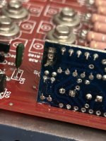
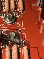
I did find a short on one of the two transistors on one of the two boards attached vertically to the PCB. See picture. It’s the green circled transistor. Bottom 2 pins read 49 ohms. The board is small and I can't see any markings to reference the schematic.
Also, can you explain what you mean by shorted base to collector? How do I know which output transistor is actually shorted? Where do you recommend I purchase them and how can I confirm that I will receive them with the same production and manufacturing? The schematic says they are TIP142. I can't confirm until I separate them from the heatsink. Can I go ahead and just order what the schematic says? Any tips on separating the PCB from the heatsink?
Attachments
Last edited:
Do the outputs still read shorted with that driver transistor removed?
Look up the datasheet for the outputs for pin names.
You would not be able to tell which was shorted with this amp since they have no base resistors. You'd have to remove them, after confirming that the driver isn't the problem.
Mouser or digikey.
Unless you buy a full stick (far more than you need), you won't be guaranteed that you get matching parts. Even then, there's no guarantee.
49 ohms could be a resistor.
Unscrew all of the screws and lift it up... After confirming....
Thanks for the help. I will probably not be able to remove the driver board transistor until this weekend but yes I confirm that Q2-Q6 all have the base and collector pins fully shorted (0.1 ohms). Also the matching transistor on the other driver board does not have any resistance.
I removed the amp driver board transistor and it's not the problem. I tested the legs of the removed transistor and none are shorted. The driver boards through holes still have a resistance of 49 ohms and Q2-Q6 still have the base and collector legs shorted.
Quick question about the best method for removing transistors. I first tried the "spread solder across the legs"method but the bridge between the legs would not last as the solder was being sucked up by the legs of the transistor. So I resorted to using desoldering braid to remove as much solder as possible and then gently wiggled each leg as I heated it up until it came loose. Took a long time and lots of heating which had me worried for the PCB. In the end it was all fine.
Quick question about the best method for removing transistors. I first tried the "spread solder across the legs"method but the bridge between the legs would not last as the solder was being sucked up by the legs of the transistor. So I resorted to using desoldering braid to remove as much solder as possible and then gently wiggled each leg as I heated it up until it came loose. Took a long time and lots of heating which had me worried for the PCB. In the end it was all fine.
Will the tip of your soldering iron bridge across all 3 legs if you lay it down across them?
If you stand the stand the transistor up straight and heat from the other side of the board and doing as suggested above (and applying additional solder to help bridge the gaps), the transistors will generally fall out from gravity or with a little help. If you have hemostats or something similar (not a pair of vise grips), hang that on the transistor that's being heated.
If you stand the stand the transistor up straight and heat from the other side of the board and doing as suggested above (and applying additional solder to help bridge the gaps), the transistors will generally fall out from gravity or with a little help. If you have hemostats or something similar (not a pair of vise grips), hang that on the transistor that's being heated.
The tip of my iron reaches 2 pins but not 3. It's a pretty basic USA made 25W iron. I also have a hot air station if that's a better option. Or would you recommend a better soldering iron? If so, any recommendations? What are your thoughts on a desoldering pump?
Last edited:
DS017 is the only decent desoldering pump I found. Only buy directly from Edsyn.
To get a decent iron with a thermostatic control (not just adjustable) you're probably going to have to spend between $100 and $150. The entry level (with true thermostatic control) Weller irons are likely a good choice. Some prefer Hakko. I never needed to try them. My weller irons lasted forever (well over a decade).
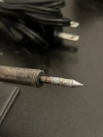
Post a photo of the tip of your iron. I've never seen one so short that it couldn't bridge those narrow pins when laying down.
Whatever you do, don't damage the board. Those transistors should drop out in less than 5 seconds.
To get a decent iron with a thermostatic control (not just adjustable) you're probably going to have to spend between $100 and $150. The entry level (with true thermostatic control) Weller irons are likely a good choice. Some prefer Hakko. I never needed to try them. My weller irons lasted forever (well over a decade).
Post a photo of the tip of your iron. I've never seen one so short that it couldn't bridge those narrow pins when laying down.
Whatever you do, don't damage the board. Those transistors should drop out in less than 5 seconds.
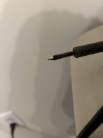
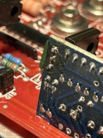
That’s not good. I applied heat for much longer than 5secs. I did notice the trace leading to the bottom pad is exposed a little. I checked continuity between the pads the trace connects and it’s fine. I tried inserting the transistor back and the holes are so little that is doesn’t go through. Unfortunately I will have to apply more heat to feed the transistor through. Here are pics of the pads and the iron tip.
Attachments
Scuff the tip back farther to see if you can get it to take solder.
When you replace/reinstall the transistors, solder from both sides of the board.
Is a good soldering iron in your budget or out of the question?
When you replace/reinstall the transistors, solder from both sides of the board.
Is a good soldering iron in your budget or out of the question?
I did as you said and sanded the tip farther back and then tinned it all. Looks better. I then reinstalled the transistor successfully and easily. All traces coming to each leg tested successfully too. As for a new iron I’m thinking about it. Maybe a used one. Should I go ahead and order the q2-q6 transistors? The schematic says they are TIP142Ts. Jameco has them in stock.
https://www.jameco.com/z/TIP142T-ST...ington-NPN-100-Volt-10-Amp-TO-220_890445.html
https://www.jameco.com/z/TIP142T-ST...ington-NPN-100-Volt-10-Amp-TO-220_890445.html
Attachments
Can you now lay the iron across all 3 legs of the outputs and drop them out?
Jameco?
What I'd like to see you do is to find the one bad output (hopefully the first one you pull), reinstall the remaining good ones and see if there is any other damage, before ordering parts.
Use octopart and try to find an authorized distributor that has stock.
Jameco?
What I'd like to see you do is to find the one bad output (hopefully the first one you pull), reinstall the remaining good ones and see if there is any other damage, before ordering parts.
Use octopart and try to find an authorized distributor that has stock.
The tinned portion of the tip does reach all three pins now. Tomorrow Ill start removing the pcb from heatsink and see if I can easily remove one of the transistors. Any particular one that is more likely to fail of the set? Do you recommend I straighten the transistors prior to applying heat? Also do you recommend applying flux before applying solder? Also is this solder good for this application?
https://encrypted-tbn0.gstatic.com/images?q=tbn:ANd9GcSBnHXSj3ikHOgd8H50ORuKAJncSWT31PvJ2g&usqp=CAU
https://encrypted-tbn0.gstatic.com/images?q=tbn:ANd9GcSBnHXSj3ikHOgd8H50ORuKAJncSWT31PvJ2g&usqp=CAU
Attachments
- Home
- General Interest
- Car Audio
- Soundstream Rubicon 502 with DC voltage in right channel