Confirm that there are no solder bridges from when you removed it. If not, you can power it up with only one of the parallel group out of the circuit.
If it powers up with no DC, clamp all of the transistors down and see if it will produce audio. You will have to lay Q2 on the heatsink so the screw can tighten up against the other transistor under that screw.
It's important that you carefully reinstall the screws, finding the original threads. If you have to disassemble the amp repeatedly, you can strip the threads in the heatsink.
If you turn the screw backwards you will be able to feel it drop down into the lead-in thread, then you can turn it the right way to screw it in.
Thanks. Here is my extensive test process and results:
1. checked for solder bridges.
2. Removed Q2 transistor
3. checked the resistance of Q2-Q6 pins 1 to 3 (1=base,2=collector,3=emitter).
a. 1 and 3 immediate and steady 3.17k
b. 1 and 2 increasing or decreasing but didn't wait to see how high it would go.
c. 2 and 3 same as (b)
4. powered on amp and obtained 33Vdc again on right channel. Immediately shut it off. Was powered less than 5 secs.
5. Checked the resistance of Q2-Q6 pins 1 to 3 (1=base,2=collector,3=emitter).
a. 1 and 3 increasing from 2.1k to 3.17k as it approaches 3.17k it gets slower at increasing and then stops there. Repeats each time I touch it or swap leads.
b. 1 and 2 shorted at .2
c. 2 and 3 Same as (a)
6. I decided to continue the experiment and so I reinserted Q2 without soldering and with no heatsink and made sure the contact was firm on all pins.
7. powered on amp and obtained 33Vdc again on right channel. Immediately shut it off. Was powered less than 5 secs.
8. Checked the resistance of Q2-Q6 pins 1 to 3 (1=base,2=collector,3=emitter).
a. 1 and 3 immediate and steady at different high values seemed dependent on the values of (b) and (c) below
b. 1 and 2 slowly increasing sometimes to 260k and stopping other times to infinity. Took about 3-5mins. The higher it went the slower it increased. Other times decreasing from 2000k. Couldn't make out a pattern. Never shorted.
c. 2 and 3 Same as (a) but seemed to max out at 80k except if I tested 2 and 3 immediately after 1 and 2 was completely at 260k then 2 and 3 would read 80k immediately.
In conclusion Q2-Q6 go back and forth from shorting the base and collector pins for no discernible reason.
Last edited:
Plenty of flux. Saturate the braid with it. Lay it along the length of the driver board and pull off all the solder you can. After that, again with enough flux, snip the end of the braid to expose clean strands and work the end of the braid into any connection that's not clean. The braid will absorb better from the end and works better than from the side. Keep snipping to have fresh braid as you get the last solder.
Don't stress the solder pads when doing this. They can be fragile, especially for those with only fine traces connected to them.
Don't stress the solder pads when doing this. They can be fragile, especially for those with only fine traces connected to them.
Excellent advice. Thank you so much Perry. I found this interesting thread.
https://www.diyaudio.com/community/...-card-rebuild-or-possible-replacement.210777/
What are your thoughts on the rectifiers being bad or the solder joints on the driver board. This amp was recently shipped to me and I was told it was working prior to being shipped. If he was being honest could shipping have loosened a bad solder joint?
Car amps can generally take a beating. They survive bass heavy cars and rarely have a problem from the vibration.
The solder connections can fail but that's also rare.
I don't know that these amps have rectifier problems. It was a problem with the older amps, however. That said, I didn't see many of these amps.
The solder connections can fail but that's also rare.
I don't know that these amps have rectifier problems. It was a problem with the older amps, however. That said, I didn't see many of these amps.
Perry great news. I think I found the issue. Dc voltage is gone from the speakers and all the output transistors read infinite resistance across all legs. I gave a healthy dose of Deoxit spray to all the switches and moved them back and forth a lot. I had done this a little at first but I guess it wasn’t enough. I assume that the changing resistance of the base and collector legs was caused by the weight of the pcb balancing on some of the switches and as I moved the pcb around the table top it would slightly affect the contacts inside the switch. I attach the pcb to the heatsink and try audio next. The switches on these old soundstreams have definitely proven to be problematic.
I don't think that's possible. If you're going to test it, insert a bipolar capacitor in series with the speaker to protect it from DC if the problem returns.
I ran another test that the amp had previously failed. I switched the amp to bridged mono mode and tested for Vdc on the bridged speaker connections and it’s working fine. Thanks for the tip on protecting the speakers. I would think high quality amps would have this protection included in the circuit. How do I know the capacitance to use? Do I just add in inline on the positive terminal? Can I leave the capacitor in place permanently as part of my install in the car?
The value needs to be high enough to prevent it from blocking the lowest frequency you want to pass. If it isn't for bass, a 100uf bipolar at 100V would be OK.
It can go in either the positive or negative speaker line.
I thought more would be wrong with it (I still don't think the switch could be the problem) because an amp has feedback and if it senses that there is DC on the output, it will generally drive the other half of the outputs to pull the DC back to 0v. This will generally cause excessive draw and drive the amp into protection (over-current), even if the amp has no DC offset protection.
Well I don’t know how it’s working but I won’t complain. Like I said earlier, all I did was clean the switches. I even still have Q2 only inserted in place. I will solder it and install the heatsink next. Im having a hard time finding a small or inexpensive dow corning 340. The cheapest I found from a reputable dealer was 100g from Newark for $30 shipped. Amazon and ebay have sellers with 1oz for about $12 but the container is not from the manufacturer and I worry it could be fake. Any other places I can look besides octopart?
Also I want to test the amp on both mids/coaxials and a sub. Can I use this formula to get the right capacitance for each setup?
fc = 1/(2π*R*C)
Therefore,
4ohm coaxials:
C = 400 uF; fc = 100 Hz
2ohm sub:
C = 4000 uF; fc = 20 Hz
Also I would really like to repair my mb quart speaker that this amp blew. Any recommendations?
See if MB quart will recone it.
I wouldn't use a cap on the sub but it may be OK. This amp doesn't produce that much power.
Don't agonize over the heatsink compound. There isn't a big difference unless it's all dried out. The DC 340 is what I used but not the only thing that will work.
I wouldn't use a cap on the sub but it may be OK. This amp doesn't produce that much power.
Don't agonize over the heatsink compound. There isn't a big difference unless it's all dried out. The DC 340 is what I used but not the only thing that will work.
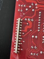
Hey all. Im back. Well after days of the the issue looking to be solved it came back. This time it was on the heatsink so I let it run for a few minutes and I noticed that the 2 transistors in the drive board got very hot and began giving off a plastic odor at which point I shut it down. Id rather buy a new driver board instead of swapping it for the other one to just have to swap it back. Where can I buy one besides the ebay seller originalparts_nos who is offline? Also seriously considering an oscilloscope. Would it make debugging this amp much easier?
The driver board components could be overheating because they're trying to compensate for problems on the main board.
What's your budget for a scope?
What's your budget for a scope?
Im looking for a used one. Either digital or analog. From my research I just need to it to be 20mhz or higher and one channel should be enough. As for accessories I think I only need 2 probes. One for ground and the other one for the signal im probing. Hoping to find it under $100
A 2 channel scope is preferred (by me), especially for an analog scope (also preferred by me).
The definition of probes will vary. It appears that you are referring to a multimeter type scope. A BNC type probe is coaxial so it has both ground and the signal conductors.
Under $100 is going to be tough unless you get really lucky.
Just think about the money you could put towards the scope if you don't buy a driver board that you don't need.
Lucky for me then because I have a local seller with a few older analog dual channel oscilloscopes for sale under $100.
- Home
- General Interest
- Car Audio
- Soundstream Rubicon 502 with DC voltage in right channel