Not had a problem myself. Its role is to eliminate Miller effect thus reducing non-linear capacitance in parallel with Cdom, as well as the extra current gain which reduces IS swing and reduces its distortion too.

The problems aren’t with stability. Recovery from overdrive is poorer unless steps are taken. It either needs a Baker clamp or an explicit current limit for the VAS transistor itself. Some will band aid it by putting a resistor in the collector of the buffer, but that’s the wrong solution because you’re back to Miller multiplying the nonlinear Cob of the buffer. And then you have another non-dominant pole thats not so non-dominant and can eat into phase margin (and hence stability). Best to leave that resistor out and deal with overdrive another way.
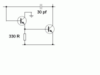
Use a MOSFET instead of a BJT as the input transistor of the two transistor VAS pair: you get infinite current gain, i.e. infinite "beta enhancement". It works quite well on the Hornet front end card for the Ship Of Theseus power amp.
A cascode is another way to eliminate the Miller effect. It will cost a few volts in output swing.
Ed
Ed
But the emitter-follower is arguably a better approach due to the increased current gain and no loss of output swing. I think both techniques allow a less performant transistor to be used as common-emitter device too, which is handy.
The best choice depends on the rest of the circuit.
The cascode will push the pole on the intermediate node to a higher frequency than the emitter follower. The reduced swing is not a problem with an additional supply rail.
Ed
The cascode will push the pole on the intermediate node to a higher frequency than the emitter follower. The reduced swing is not a problem with an additional supply rail.
Ed
Like an MPSA42 driving a TIP50 at crazy voltages…..But the emitter-follower is arguably a better approach due to the increased current gain and no loss of output swing. I think both techniques allow a less performant transistor to be used as common-emitter device too, which is handy.
lets say the VAS is being run at 5mA, what guidelines are used to figure out the current through the buffers emitter resistor ?

A milliamp and a half. Get it into a linear operating range, and keep the current swing small. It’s only really a difficult selection if driving a symmetrical VAS that can go into class B.
Every circuit I've seen uses 1k for the buffer, its probably not very critical. Too low a value will load down the input stage and make it less symmetrical.
I simulated that many times and do not see any changes in the phase margin and distortion with that protection resistor (used up to 6k) and without it. I have problem burning that transitor overdriving Self amp, and he does use not any collector resistor there.Some will band aid it by putting a resistor in the collector of the buffer, but that’s the wrong solution because you’re back to Miller multiplying the nonlinear Cob of the buffer. And then you have another non-dominant pole thats not so non-dominant and can eat into phase margin (and hence stability). Best to leave that resistor out and deal with overdrive another way.
By the way I use that resistor in my amps.😊
If you took all the trouble to get a buffer with a 2 pF Cob, why would you let it multiply? Let the linear capacitor you put there multiply, not the nonlinear one in the transistor. I usually current limit the VAS anyway - so it won’t toast when the SOA limiters kick in. I know, doing that requires putting in an emitter resistor and some are going to want to get rid of that entirely.
It is not VAS transistor toasted but beta enhacing transistor. Could you show the formula to calculate Cob multiplied depens on that resitor?
Correct. But when you cut off drive to the composite VAS stage, the current thru the buffer is also limited. If you only limit the current thru the buffer, overdrive can’t hurt the buffer but clamping the VAS output won’t be good for it since with the buffer you won’t run out of drive when the LTP fully slams over. By the time the buffer finally limits the VAS may be overcurrent.
The cob of the buffer gets multiplied by the AC gain to its collector. Get rid of that AC gain, no multiplication.
The cob of the buffer gets multiplied by the AC gain to its collector. Get rid of that AC gain, no multiplication.
Last edited:
So with that resistor with two times higher value then emitter resistor there is the gain of two?
I connect the VAS current limiting transistor colector to the VAS transistor base not the enhacement transistor base. If I connect insted this transistor to enhacment transistor base there is other type degradation of te Cob. ??
I connect the VAS current limiting transistor colector to the VAS transistor base not the enhacement transistor base. If I connect insted this transistor to enhacment transistor base there is other type degradation of te Cob. ??
Hanging the current limit transistor to the input of the buffer adds a bit to cib, not cob. You can use a stack of diodes to clamp the input to the buffer/VAS too. Works as long as there is a sensible value emitter resistor in the VAS. Capacitance of the diode stack can be lower than a limit transistor.
- Home
- Amplifiers
- Solid State
- About beta-enhancing emitter-follower buffer between the input stage and the VAS