LUXMAN 117 Help Please II

I am still having problems with a vintage Luxman 117, but narrowed down the issue with one channel dropping out . From what I can see with a flashlight there is a separate board that the RCA inputs are connected and thinking there is lose connection, or cracked around the RCA because with a push - it moves slightly [down] and the sound returns.
Question, has anyone removed the far rear circuit board on a Luxman M-117?

Sony LBT-A590 Amplifier Relay not clicking, Volume knob blinking and no sound

A friend of mine recently moved and didn't want his old system which was the Sony LBT-A590 Amplifier and some other thing which aren't relevant for this thread. when I wired everything up and tried to test it out I noticed when I turned it on there was relay click sound and no sound came from the speakers, I made sure the speakers were fine and the input was fine which the amplifier a screen showing the EQ in which I saw that there clearly music playing. I also noticed that the volume knob light was blinking and when I looked up videos of the device when other people was playing it the volume knob light was solid which has to have a meaning but I can't figure it out, I also tried resetting the device which I couldn't figure it out also. then I downloaded all the manuals (the service manual and the operators manual) to which I couldn't find any helpful information. I made sure that all the fuses were fine, tried searching for fixes online in which I found none beacause the device was very old. any ssuggestions? Service manualOwner's manual

Attachments

  • IMG_20220720_235210.jpg
    IMG_20220720_235210.jpg
    461.9 KB · Views: 669

For Sale Supravox 400 GMF Limited MK2 Revision - 16" / 97dB / 20Hz - 5000Hz / 8 Ohm / 120W / 40cm

A brand new, unused matched pair of Supravox 400 GMF MK2 drivers which were made in 2020 in limited order before shutting down this product line.
One of the best 15"-ish drivers and better than the current 380 GMF which Supravox is selling.
However, I will use 12" in my project so these are unnecessary.
RRP: €1500
Made in France.


70d1071352218630.png

  • Membrane material: Paper;
  • Efficiency: 97dB;
  • Usable frequency range: 20Hz - 5KHz;
  • Impedance: 8Ω;
  • Power: 120W;
  • Fs: 21Hz;
  • Re: 6.5Ω;
  • Qts: 0.2;
  • Qes: 0.21;
  • Qms: 10;
  • Mms: 70g;
  • Bl: 19.6;
  • Cms: 0.47;
  • Sd: 855 cm2
Price for the pair: €999

========

Will be shipped securely.
Location: Sofia, Bulgaria
Contact me here or on email veselin.karavelov@gmail.com

Attachments

  • 20191112_173549.jpg
    20191112_173549.jpg
    409.5 KB · Views: 343
  • 20191112_173550.jpg
    20191112_173550.jpg
    237.8 KB · Views: 347
  • 20191112_173551.jpg
    20191112_173551.jpg
    258.8 KB · Views: 348
  • 20191112_173553.jpg
    20191112_173553.jpg
    258 KB · Views: 336
  • 20191112_173555.jpg
    20191112_173555.jpg
    289.5 KB · Views: 347

New project: 8inch 2way, WG, Scan Speak

As I had such a project in my head for a long time, and drivers + WG available, I decided to to put together simple (well, not that simple) 2way.
Initial thoughts of 21W in 2way were not much in favor of that driver, but the more and more I looked at it, the more I liked it. And it paid off.
21W - excellent off axis behaviour. Breakup at 3200Hz will need extra care, LR4 and lower crossover point, plus capacitor in parallel to main coil. Distortion measurement confirms breakup mirroring in HD3 and HD5.
6600 in WG - in simple baffle with almost zero edge treatment I could not hope for better result. Minor dip at 13k was expected, and proved by listening tests to be no issue.

Cabinet: 37l BR 21Hz.

After initial setup and listening there were several challenges:
1. bass was too deep and dry, midrange little bit in the back
2. trebles too forward, mild hiss signature

1. I have done several iterations of damping material adjustment and I lower the value of primary coil to achieve lower baffle step compensation. The result was exactly what I wanted, clear and clean midrange, impressive well defined bass, and good overall balance
2. I had to attenuate trebles above 2kHz by 0.7dB, and take care of 7-10kHz area, and 2.5kHz area. This brought the right balance of detail, clarity and smoothness I know 6600 was capable of.

Measurements were done with no gating, smoothing 1/12. SPL calibrated, distortion measurement with mic distance 30cm, 2.83V drivers and 6V complete loudspeaker.

Full writeup: https://pkaudio.webnode.cz/21w-6600-wg/

Attachments

  • 2way 8inch photo.png
    2way 8inch photo.png
    221.4 KB · Views: 508
  • 2way 8inch Vituix Six pack.png
    2way 8inch Vituix Six pack.png
    111.6 KB · Views: 365
  • 21W distortion.png
    21W distortion.png
    64 KB · Views: 289
  • 21W FR horizontal 0-90.png
    21W FR horizontal 0-90.png
    57.9 KB · Views: 246
  • 6600 distortion.png
    6600 distortion.png
    58.9 KB · Views: 261
  • 6600 FR horizontal 0-90.png
    6600 FR horizontal 0-90.png
    70.4 KB · Views: 252
  • loudspeaker distorsion 6V.png
    loudspeaker distorsion 6V.png
    73.2 KB · Views: 326

Questions : Amp Gain and AV Receiver Pre Out

Hi Everyone.

Can someone please help me with these questions.

1. What is the Gain of F5 Turbo V3(44V Rail voltage) and Aleph 2(55 V Rail voltage).
2. What is the Gain of AV Receiver SR6007 (https://www.marantz.com/en-us/product/av-receivers/sr6007)
3. I'll be using PRE OUT from AV receiver to feed F5T and Aleph2. Can I use PRE OUT SW1(Subwoofer1) and SW2(Subwoofer2) as input to Aleph2?


Thank you

Attachments

  • Img.png
    Img.png
    155.6 KB · Views: 93

Looking for IGBT amplifier schematics?

Hello, I only know about IGBT for powered a 1500V motor in a train, a good compromise between Transistor and MOSFET.
But in the audio world I would like to know how it sounds. The only amplifier schematic I see is in this french magazine :
http://www.electronique-3d.fr/PDF/Ampli-90W.pdf
Do you know about other Igbt amplifier ? Have schematics ? Heard to the sound ?
Thanks in advance 🙂

Sell capacitor 1,000uf 6v Brand ROE

Sell capacitor 1,000uf 6v, sell as a set, set of 10, price 5 usd, direct mail from Bangkok, pay by paypal plus shipping (shipping cost will be informed later when knowing the destination address)

Attachments

  • 1686635803793.jpg
    1686635803793.jpg
    207.6 KB · Views: 64
  • 1686635803600.jpg
    1686635803600.jpg
    205.3 KB · Views: 68
  • 1686635803243.jpg
    1686635803243.jpg
    196.1 KB · Views: 65
  • 1686635804740.jpg
    1686635804740.jpg
    173.8 KB · Views: 60
  • 1686635804324.jpg
    1686635804324.jpg
    243.4 KB · Views: 59
  • 1686635805585.jpg
    1686635805585.jpg
    218.5 KB · Views: 58
  • 1686635805139.jpg
    1686635805139.jpg
    221.8 KB · Views: 60

The most robust dome tweeter available?

Hey folks…..so I’ve got to put together a very low profile center channel for a 7.1.2 Atmos system for a client…..can’t be taller than 4.5” cabinet so a dome is a must. Nothing available commercially that won’t have severe off axis issues so I’ve got to get that XO point down to 1k with a steep slope. Its gotta be able to keep up and do 105db……any domes that can do this currently on the market?

  • Locked
Churchill Downs Shutting Down Horse Racing Operations

Churchill Downs announced last week that they are shutting down horse racing operations at the track to examine safety measures.

Also, here is an excellent piece by a lifelong horse person regarding the current racing situation.

https://www.cnn.com/2023/06/08/opin...orse-racing-deaths-doping-ban-irby/index.html
  • Like
Reactions: adason

For Sale Digital Audio Labs CSX-01 CardDeluxe

24/96 PCI professional audio card, was a recording industry standard, great for measurements $100

CardDeluxe WDM/ASIO device driver (5.10.3523) (Windows® XP/Vista/7; 32/64-bit)

CardDeluxe WDM ASIO Driver for Windows 7/10 64 bit Driver

Here are FFT plots, driving inputs with 1Vrms from AP and sending 1Vrms from CardDeluxe to AP. I don't have PCI slot for it anymore

Attachments

  • IMG_1686.JPG
    IMG_1686.JPG
    228.5 KB · Views: 141
  • IMG_1687.JPG
    IMG_1687.JPG
    168.5 KB · Views: 142
  • left input.PNG
    left input.PNG
    18.5 KB · Views: 127
  • right input.PNG
    right input.PNG
    18 KB · Views: 127
  • left output.PNG
    left output.PNG
    6.5 KB · Views: 129
  • right output.PNG
    right output.PNG
    6.6 KB · Views: 144

NOS Parts: Carbon Comp (30+ 2 watt values) and Metal Resistors; WW 10 Ohm Pots; 1W Bourns Trimmers; and More!

Hello,

I am downsizing my apartment, so I'm trying to sell off some parts. Stock your parts bin! I will beat prices at surplus retailers. Due to the hassle of shipping, I don't really want to sell individual components. Please only reach out if you are interested in ordering a decent quantity. This will work best if you're a tech etc. Big discounts for volume purchases.

I am located in the US and willing to ship internationally.

Wirewound 10 Ohm 5 Watt Linear Pots (bulk):

I bought these from the estate of Dick Sequerra and have been selling them for a while. I think they were used in speaker crossovers.

They are flawless and un-corroded on the inside. Every single one I have tested has been good electrically. However, the oil in the shafts is a bit stiff, so they turn best if they are re-lubricated. Also, the terminal plating has corrosion which should be wiped off with contact cleaner. Afterwards they work well and take solder.

Selling in as-is condition. I have two boxes, one of which is full (1,000 potentiometers) and the other of which has about 900 remaining. I also have a couple hundred loose. They come with washers and nuts for mounting. 5 watt wirewound pots cost like $5 a piece now from major distributors; I'm willing to let these go for like $.20 a piece. A great deal if you use these frequently. Would love to sell a whole box.

Carbon Comp Resistors

I have a ton of carbon comp resistors, mostly 2 watt, but also very large quantities of some other values. Please reach out with the value you're interested in and I'll give you a quantity. I have many boxes of high-value resistors (1M ohm plus) and would really like to get rid of these.

All of these resistors are totally NOS, never soldered or used. Some were stored loose and have slightly bent leads. There is no water damage or anything and the paint is in great condition. Some of them do have slight corrosion on the leads as expected given the age. I might have missed some values, so if you're interested in a value I don't have listed, feel free to PM.

2 watt values:

13
15
160
240
330
390
420
430
560
620
680
1.8K
7.5K
8.2K
9.1K
11K
13K
16K
25K
56K
62K
82K
120K
130K
360K
820K
910K
1.2M (very low price)
1.8M (very low price)
2.7M (very low price)
3.3M (very low price)
5.6M (very low price)
6.8M (very low price)
12M (very very low price)
22M (very very low price)

1 watt values :

18
51 (500+)
750
12K
2.2M (500+; right angle leads)
6.8M

1/2 watt values:

3.9K
4.7K (I have like eight boxes of these; probably 6,000 plus in total. Some have pre-bent leads. Would love to sell some boxes.)

1/4 watt values:

270 (1,000+; good for cathode bias)
390 (good for cathode bias)
1K (good for cathode bias)
2.2K (1,000+)
4.7K (good grid stoppers)
10K
33K
100K
240K
330K
1M (500+; good for grid leak)
10 M (1000+)

I haven't catalogued all my 1/4 watt CC resistors yet, so let me know if you need anything specific and I'll look.

Metal Film/Oxide (have hundreds of each of these):

Some of these are pretty rare and unusual, so if you enjoy parts rolling they could be fun.

3.01K 1/4 W 1% (RNR60C3011FS hermetically sealed mil-spec resistor by MEPCO/Electra. The resistor is hermetically sealed inside an outer glass shell. Extremely cool appearance and super expensive from a real distributor. Datasheet says these are used in missile guidance and other mission critical applications. Makes for a hilarious grid stopper or cathode bias).

5.2K 1/2W (?) 1% (Says EKC on resistor. They have a loose plastic outer shell, no idea why, never seen anything like it. Think 1/2 W based on testing and size but not marked. Very cool appearance. I use them as grid stoppers).

9K 1/2W 1% (RN60D9001F Mil-Spec metal film; have 1000+ on reel tape).

18K 1/4W 1% (RL07S183G; precision metal film resistors in great condition on reel tape).

47K 2W (?) 5%ish (Interesting resistors, military drab green color. Looks like a very early metal film/oxide type. Only marking is "47K" and a dot of orange QC paint. Based on my testing they handle 2W but 1W or less is preferable. They seem to be about 5% but have no tolerance marking. Lead plating looks exotic -- has a slight golden sheen. Each one is packaged individually in a cardboard tube. Great plate loads).

180K 1/2 W 1% (Corning Glass Works N20. There is a datasheet for these online. A high quality, low drift part. Jet black vintage appearance -- they look great).

Bourns Trimmers:

25K 1W 25-turn
(3250P-67-253; I bought these at a military surplus auction and have the demil paperwork. These are high-quality Bourns trimmers in their original tubing. Great for critical applications that require the trimmer to dissipate a bit of heat, such as AC balancing differential plate loads. A somewhat exotic part not available from normal distributors).

Axial Tantalum Capacitors:

180 uF 25V 20%
(NCI HNW 7449; These are expensive axial tantalum capacitors with a grey metal body. They have the same high-quality look as vintage Sprague electrolytics. Great for cathode bypass or decoupling. Tested at rated voltage and guaranteed working).

DPDT Switches:

3A 250V / 6A 125V, panel mount
with solder lugs (Made by UND Lab Inc. A great, chunky vintage DPDT switch. Comes with plated metal inner mounting nut and black anodized outer nut which matches color of switch. Very similar (if not identical) to toggle switches used in vintage test gear like Power Designs. I have a lot of these and would love to sell 10-20 at a time).

Nakamichi MB-K1000

I just purchased one of these nakamichi mb-k1000 music kiosk setups which I suspect with the closure of some music stores will become more available as time goes by.
I'm waiting for it to arrive. Does anybody here have any experience with these... there seems to be very little info available on the web.

I play so little CD these days, almost entirely LP with some streaming music, I thought it might be interesting to have this to play around with. It may end up collecting dust or I might get some use out of it, we will see

Paraller SE E88CC/KT150 tube amp design

Hello 🙂

I am designing my first tube amp. Before I start assembling, I'd like to get approval or advices from more experienced constructors 🙂
The project is a simple, two-stage parallel single ended, based on the e88cc/6922 and 2 x KT150 tubes per channel.
The amplifier is designed for the triode mode, although the ultralinear option is also provided.


Low THD was not the goal of the project. I care about a favorable ratio of even to odd harmonics and a warm, saturated tube sound. The LTSpice simulation shows just over 5% of the second and 0.2% of the third harmonics at full power. Of course, in real life, the results may be different than simulated 🙂


Less parts
No grid stoppers for the driver tubes - the volume pot will fulfill this role(?)
No grid stoppers for the power tubes
No coupling capacitor at the input - I assume that the capacitor is at the output of the source (DAC)


Cathode bypass capacitors for the driver: Nichicon FG. The Nichicon KZ is positioned higher, but its sound is supposedly less warm.
Elna Silimic might have been better, but nowadays it's probably hard to get a better version (ARS, AXF) than the standard RFS.


Driver anode choke:
Lundahl LL1668-15mA
(Coils in Series, DC Resistance 680Ω, x 235V~ 100Hz Ripple, 15mA 167H)
The choke is designed for 15mA, but according to the website
http://jacmusic.com/lundahl/applications/How-to-bias-the-LL1667-LL1668.pdf
...DC current can be exceeded if the AC signal voltage is lower.
LL1667-15mA (Coils in Series, DC Resistance 2400Ω, x 390V~ 100Hz Ripple, 15mA 270H) has a higher inductance, but the forums say that 1668 sounds better than 1667.


The output transformer has 1500 ohm impedance, so each of the two power tubes sees a little over 3000 ohm (the screen current must also pass through the transformer's winding and it seems to raise the impedance)
I am also considering a transformer with an alternative lower impedance tap to achieve more power.


PSU is a very important part of every amplifier - in order not to make a mess in this thread, I will present the PSU circuit (as well as a fixed bias circuit for power tubes) in another thread, when I get approval for this project.


So...
  • Won't it explode? 😉
  • Does the presented circuit make sense?
  • Is there a chance that the construction will sound decently?
  • Did I forget something?


Thanks in advance for any suggestions or comments!
Rafal

Attachments

  • TubeAmp.png
    TubeAmp.png
    142.3 KB · Views: 680

DavidLouis 4ohm 104BE25-4 Pure beryllium dome tweeter Nd magnet & davidlouis BE28 pure beryllium Be dome tweeter speaker Nd magnet. ANY GOOD?

Hello all,
Does anyone have any experience with either the DavidLouis 4ohm 104BE25-4 Pure beryllium dome tweeter Nd magnet or the davidlouis BE28 pure beryllium Be dome tweeter speaker Nd magnet? I can't really find anything online. (good or bad...) Please advise... Thanks in advance.

Attachments

  • EA46FAB0-5027-4161-9DF5-7D6E1ABFC9CA.jpeg
    EA46FAB0-5027-4161-9DF5-7D6E1ABFC9CA.jpeg
    214.4 KB · Views: 168
  • 492A3FCA-1B66-40CC-910F-84D561D8A97A.jpeg
    492A3FCA-1B66-40CC-910F-84D561D8A97A.jpeg
    188.8 KB · Views: 135

6V6 amp in LTSpice

Hi guys, this is my first post on the forum.
I want to ltspice my amp based on 6v6, but I don't have much idea, especially in the output transformers, I did what I could by copying some examples from the forum.

The original schematic is on this page, if anyone can give me clues on how to do it and test it.
https://diyaudioprojects.com/Schematics/DIY-Push-Pull-PP-6V6-Tube-Amplifier/

I leave you the file of what I did
it would be greatly appreciated

thanx a lot

Attachments

Twisted Pear Audio Parts

For sale are new, unused parts for Twisted Pear Audio (TPA) products:
  • 1x Buffalo III DAC with full series regulator set (3x Trident, AVCC)
  • 2x Buffalo II DAC with IVY III v1.0.1, AVCC, 3 Trident v3.0
  • LCDPS Assembled & Tested (Panasonic & Elna caps)
  • Placid HD Assembled & Tested (Panasonic cap)
  • S/PDIF Transceiver - Sold 05/08/23
  • Volumite Base Kit, Firmware for Buffalo III
  • 2 of Toslink Optical Input Module - 1 Sold 05/08/23
  • Legato 3.1 board with Parts
  • AVCC SRA 2 V-1.0 3.50V
  • Trident regulators:
    • 2x VDD 1.2V v1.1
    • 2x DVCC 3.3V v1.1
    • 1x VDD_XO 3.3V v1.1
    • 3x AVCC AVCC_SR_1.0
    • 2x AVCC SRA V-1.0 3.50V
  • 1x Placid HD 3.1 Power supply board with all parts
  • 2x Placid HD 3.1 Bipolar Power supply board with all parts
  • Toroidal transformers for Placids
    • 1x 25VA 9V, double secondary AnTek AN-0209
    • 3x 25VA 15V, double secondary AnTEk AN -0215
    • 2x 52VA, 2x 15V, 1x 9V by Primrose Audio Design (ideal for dual mono build perhaps)
  • Legato 1.0.3 board with all parts
  • Legato 3.1 board with all parts

The part would ship from Massachusetts, US. Please send a private message.

IMG_6658.jpg

IMG_6659.jpg

IMG_6662.jpg

IMG_6632.jpg

IMG_6636.jpg

IMG_6672.jpg
IMG_6673.jpg

Cabinet material Measurement

Here are some measurement from the excellent German magazine (what happened to the football team?)
The setup a wide band driver set in a box within a box

A front baffle is added and two things are measured. The sound througput through the board and secondly the vibrations of the board is measured with a contact microphone

Then a set of board are compared and with 19 mm MDF as the standard both for transmission and vibration levels
Picture 1 Findings
I. The 16 mm is very close to the 19 mm in both accounts even if thinner
II. "Concretchipboard" While hard to find superior to MDF
III. Beech plywood, slightly inferior to MDF
Picture 2
I.28 mm MDF better than 19 mm but not by so much as the increased thickness suggest
II. 20 mm Slate (stone) way better than anything else!
III. 19 mm Chipboard, while inferior to MDF it is cheaper so a given amount of investment gives a thicker board...
IV. Blockboard 19mm inferior to both MDF and chipbord

I am familiar with the BBC papers that guided both the LS3/5A and the Spendor BC1. Both had thin walls and a lot of damping to get the resonances out of the harmful midrange and down to the bass to cause less harm

Attachments

  • HH-Testsetup1.png
    HH-Testsetup1.png
    40 KB · Views: 433
  • HH-TestSetup2.png
    HH-TestSetup2.png
    54.1 KB · Views: 485
  • HH-Test-Boards1.png
    HH-Test-Boards1.png
    407.5 KB · Views: 467
  • HH-Test-Boards2.png
    HH-Test-Boards2.png
    527.7 KB · Views: 461

Help Identifying an Oddball Tube Amp Chassis

Hi All!

I picked up this amp chassis for $20 today. No tubes or documentation included. The only markings are a stamped circle with "32E" inside. The over-all circuit appears to be push-pull using some kind of octal power tube like 6v6, 6l6, etc (pin 1 unused, pin 3 [plate] tied to one side of opt primary, pins 2 and 7 heater). Here's where the odd comes in. The screen grid pins (pins 4) are tied to the cathodes (pins 8), which are tied to what appears to be a filter capacitor positive voltage node. Both grids are tied together, and go to the 9-pin octal style socket. The power supply uses solid-state rectifiers, and appears normal enough. There appears to be both main B+ and a single-diode negative voltage source, and there is what looks like a bias POT with no guts which is NOT tied to the power tube grids. I can't figure out what exactly its purpose was. There doesn't appear to be any specific grounding scheme, as some grounds go to chassis, while others tie together in a semi-star style. My gut instinct is to just gut it and start a build from scratch. However, if this is a bit of a rare amp configuration worth a possible resurrection, I'd consider that undertaking.

Any help/input appreciated!

Attachments

  • 20230611_201633.jpg
    20230611_201633.jpg
    318.8 KB · Views: 136
  • 20230611_201652.jpg
    20230611_201652.jpg
    273.1 KB · Views: 128
  • 20230611_201702.jpg
    20230611_201702.jpg
    260.5 KB · Views: 124
  • 20230611_201815.jpg
    20230611_201815.jpg
    361.3 KB · Views: 127
  • 20230611_201951.jpg
    20230611_201951.jpg
    308.5 KB · Views: 116
  • 20230611_202355.jpg
    20230611_202355.jpg
    545.5 KB · Views: 116
  • Image1.jpg
    Image1.jpg
    85.2 KB · Views: 118

Coral CX-5 tweeter blown

Hi

The tweeters have blown in my coral cx-5 speakers. They are rated at 60w music, which, i assume could be around 30rms? The cutout for the tweeter is 5.5cm, just below the bottom of the cut out is internal bracing (as per photo). I upgraded the crossover and found in another forum, some one had drawn out the schematic for the crossover. I used jansen for the tweeter , mid LCR (ampohm), woofer just cross caps. Resistors, i tried the W22 from element14. Really nice sounding speakers, the midrange being its best drivers. Sounds fine without the tweeters. The attenuator doesnt appear to work, it did for the mids not the tweeter. I carefully did pull it apart and cleaned it. Its either my wiring or something else.

Ive had success with the Seas H1283 in my ESM / Seas Kenwood bookshelf speakers. I am learning towards it, and i am not sure if it suits this particular crossover.

coral cx-5 crossover.jpeg


P1460372.JPG

P1480566.JPG

P1480575.JPG

FS Biosciencegeek cMOY Headphone Amp

For sale mint (see what I did there? LoL) cMOY Headphone Amp. Asking $60. As made by Biosciencegeek, it doesn't look like he is selling them anymore (on E.....y). Using Burr Brown OPA2227, 9 volt batteries are set up to run in parallel. Base boost/gain switch, can be powered externally. Plugging in headphones turns it on.

Attachments

  • PXL_20230605_025508689.jpg
    PXL_20230605_025508689.jpg
    290.7 KB · Views: 107
  • PXL_20230605_025442878.jpg
    PXL_20230605_025442878.jpg
    312.3 KB · Views: 97
  • PXL_20230605_030120247.jpg
    PXL_20230605_030120247.jpg
    648.6 KB · Views: 123
  • PXL_20230605_025545585.jpg
    PXL_20230605_025545585.jpg
    406.9 KB · Views: 114
  • PXL_20230605_025537338.jpg
    PXL_20230605_025537338.jpg
    380.9 KB · Views: 113

Cassette decks with ribbon type connectors...

Hi, I'm looking to dip my toe into cassette tapes. I have a load of old cassettes I'd like to listen to and possibly digitise. I was looking at the TEAC H300 but these seem to hold their value quite well and are a little pricey, probably because they have a standard RCA stereo output.
I've noticed loads of Technics decks and other makes which are of a similar era and type as the H300 which go for peanuts. A lot of them use proprietary ribbon interconnects.

Im wondering if anyone has traced the connections back to figure out which wires within the ribbon cable carry the left right analogue audio signals and then retro fitted RCA sockets in the chassis of one of these decks? Seems like it should be easy enough to do.

First PCB design, any feedback before I order?

Hey, I've been working on a mic preamp in a stompbox based off this TapeOp article. I swapped out the tubes for Soviet subminiature 6N16Bs and added a H-pad at the end to reduce the voltage back to microphone level. I simulated it in KiCad and tweaked the plate and cathode resistor values until I had something I liked, and also added an L-pad after the second preamp stage to prevent the cathode follower from clipping. Anyway, I've sourced the parts, found a Hammond enclosure, and designed the PCB. I think I've followed all of the rules - 45 degree angles, keep audio and power ground separate, star ground for audio, avoid crossing traces, and if it's unavoidable, have them cross at a 90 degree angle. This is my third PCB design iteration and I think I'm ready to place an order. But before I do, I thought it would be wise to ask for feedback.

K1 and K2 are relays controlled by the footswitch.
T1 is the input trafo, T2 the output trafo.
There are two POT_GNDs because the cables are shielded.
U1 is configured as two cathode-biased preamps, and U2 as a White cathode follower.

The trafos and balanced input and output connect on the bottom of the board.

The footswitch has its own pcb (at the bottom) that I'll cut off. It will stand above the the empty spot at the bottom middle.

C8 is a decoupling cap, the others are all coupling.

The power source is a tiny (25mm x 25 mm) nixie tube power supply. It will sit under the board, below the output trafo. I'm going to add a grounded copper pour under the output trafo to provide some shielding, but if that's not enough, I'll have enough clearance to put a shield between them.

The audio path goes from the balanced input XLR (IP2/IP3) to the input trafo primary (T1-ORG/T1-BRN). The unbalanced secondary (T1-GRN) goes to via the grid stop (R19) to U1, then from U1 to POT_OUT to a gain pot, then to POT_IN, to C3, back to the second triode in U1, then to R16. That goes directly to the cathode follower U2, which outputs to to C6, then to T2-B (output trafo). Finally, the secondary output (balanced - T2-G/T2-Y) goes through the H-pad at the top left before entering K2 and finally to the output XLR (OP2/OP3).

When the coils of K1 and K2 are disengaged, IP2/3 and OP2/3 are connected directly and the H-pad becomes a dummy load.

Any feedback on my placement and routing? F.Cu is red, B.Cu is blue. All audio ground is routed on B.Cu.

Thanks!

Screenshot 2023-05-06 at 8.13.24 PM.png

Greetings from Finland

Hello! I've been lurking around the forum for about three years and decided to join and wanted to introduce myself.

First of all I'm amazed and grateful for the huge amount of knowledge and experience the members here have and that they are willing to share it too. Without it my road to designing and building my first speaker set would have been a lot harder. Been listening to them for about 18 months and I like them although the enclosures require some ( a lot of ) finishing but I've never gotten around to it since aesthetics are not that important to me
20230611_211618.jpg
  • Like
Reactions: Juhazi

Mystery ‘Concord' mixer amplifier with mystery output transistors

Hello,
I am trying to fix this mixer/amplifier:

IMG_20230608_200638083.jpg


Unfortunately, I can't find any information on it, let alone a schematic. does anyone have a clue?

The problem seems to be the output transistors, at least one of them (the NPN one) measures short circuit between collector and emitter. Can't be good. But here to, I am unable to find any reference. Here they are:

IMG_20230608_200752270.jpg


Looking at the PCB, I see no driver transistors, so I think the above individuals are darlingtons. But how to know? with my multimeter on diode check, the readings are:

NPN:

C to E short circuit
B to E 0.6v
B to C 0.6v
E to B 1.8v
C to B 1.8v

PNP:

C to E infinite
E to B infinite
C to B 0.6v
B to E infinite
B to C 1.5v
E to C infinite


Any help is very welcome,

Gijser

MathAudio Room EQ for Foobar2000

mathaudio-room-eq.png


Features:

  • Corrects deficiencies of room acoustics (multipoint compensation).
  • Corrects acoustic imperfections of speakers.
  • Optimized for maximum accuracy of the correction.
  • Corrects both amplitude and phase components of frequency response.
  • Quells resonance peaks of frequency response while leaving the deep notches to prevent large excursions of the speaker diaphragm. Avoids the muddy sound of conventional linearizing equalizers.
  • Manually adjustable level of compensation allows one to reach the maximum transparency of the sound.
  • Supports high sample rates.
  • Applies 64-bit signal path throughout.
  • Works with USB measurement microphones (e.g. MiniDSP UMIK-1) or standard measurement microphones (e.g. NADY CM100 or Dayton Audio EMM-6).
  • Supports microphone calibration files.
  • Applies a patented method of frequency response correction.
The plug-in is free.
Download: MATHAUDIO - Download
Any feedback is welcome.

MEMS Cartridge - Micro Condenser Microphone for the pickup

A patented new product from a small Japanese company. $5000. It uses 1mm condenser mics for smartphones. I'm a bit skeptical about this, but it may work very well. RIAA EQ / phono amp is not required.

The Miyaji-type MEMS cartridge has an amplitude-proportional characteristic that uses a very small high-sensitivity condenser microphone for the pickup.
It is a structure that guides the vibration of the cantilever to the left and right sound conduits and captures the sound pressure with a microphone.
The sound pressure transmitted to the microphone is equalized in the shape of the sound conduit, and the frequency characteristics of 20Hz to 20KHz are adjusted to be almost flat in the test record and aged. Since the frequency characteristics are attached to the characteristic table actually measured for each product, high-quality audio signals can be obtained. Since the MEMS microphone is a condenser type microphone, it requires a power supply and uses a dedicated head amplifier.


(Google translate)

https://arsound-jp.translate.goog/m...l=auto&_x_tr_tl=en&_x_tr_hl=en&_x_tr_pto=wapp

Help with Center DC Adjustment - Sansui B-2101

Hello everyone

I recently restored a Sansui B-2101 power amp and really tried hard.....
All caps were selected according to their specifications (low ESR, low leakage, etc.) The same values (left - right side) as possible and really the best quality (which was affordable for me). Transistors KQ 2-9 matched in pairs (as best as possible).
New thermal paste and everything you need to do a good job.

But today when comparing, I first noticed that there are errors in the SM. VR3,4 are shown reversed and the pin assignment on the 5-pin test point (picture 4-2. Top View) is different than in the picture next to the comparison table (2-2.). So far everything is still ok, since it was noticed early on.
The main problem, is the center dc 0V adjustment with VR2. There is no stable value to get. I have already exchanged the variable resistor for a 100 Ohm type because the fluctuations during the adjustment were too severe. However, I can only bring the voltage to around 0V and then the voltage starts to drift. The smallest changes on the controller let the voltage run away immediately. The adjustable range between +/- 200mV is only about a 10 degree radius.I can no longer imagine a solution.So here's my question to the real experts, is this possibly a design error or how can this happen? Is there possibly a solution that saves my day?

Attached are two pictures of the manual to understand what I'm writing about.
Thank you in advance for any help and have a nice day
Sansui madness.jpg


Sansui madness 2.jpg

Old and knackered but working Magnum Dynalab Tuner and Signal Sleuth

I have had this tuner sitting around for years, last time I lived in a place where I could get FM reliably it worked well. I bought it from eBay many years ago and it had a bunch of dodgy mods done to it. I removed some of the more egregious ones and cleaned it up, and made sure it was working well. I didn't pay a lot for it and neither should you. This also comes with a signal sleuth also by Magnum Dynalab, I never found it particularly useful, but you might.

I'm looking to give these a new home with someone who might use them. Offers accepted.

Sheldon

FMTuner - 7.jpeg
FMTuner - 6.jpeg
FMTuner - 5.jpeg
FMTuner - 4.jpeg
FMTuner - 3.jpeg
FMTuner - 2.jpeg
FMTuner - 1.jpeg
  • Like
Reactions: JRKO

Threshold SA/2 Amps One running hotter than other

I just purchased a pair of Threshold SA/2 optical bias amplifiers in their original unrestored state. They sound amazing with no noticeable issues. However, I have noticed one amp runs about 7 degrees warmer than the other(100F vs 107F)at the same midpoint on the heatsinks. Regardless of input or speaker swapping L for R channel it is always 7 degrees warmer. Should I be concerned or is this likely a bias issue I could address myself as an amateur? Or is this within a normal range of difference between amps?

Thank you

Charles

How to unstick transistor?

I am trying to replace the output capacitors in my KEF 30b subwoofer amplifier. I cannot get to the under side of the capacitors as the circuit board is connected to two transistors that seem to be stuck to the heat sink? Any ideas on how to unstick these?

Attachments

  • IMG_5996.jpeg
    IMG_5996.jpeg
    376.4 KB · Views: 146
  • IMG_5998.jpeg
    IMG_5998.jpeg
    422.2 KB · Views: 137
  • IMG_6002.jpeg
    IMG_6002.jpeg
    435.4 KB · Views: 150
  • IMG_6007.jpeg
    IMG_6007.jpeg
    406.4 KB · Views: 140

For Sale Leaving the hobby

Everything is for sale. Valves, small tools, soldering gear, semiconductors, chip amp parts and PCBs, transformers, etc.

I'm fully aware the there's quite a bit of junk here, but what doesn't sell is going in the skip - if you can use something make an offer. Preference given to larger offers - make me an offer on all of the caps, or all of the semis, or all of a certain type of valve, for example. If you cherry pick the best stuff, the prices aren't as negotiable.

Prices are Australian dollars and do not include shipping. Payment by EFT is preferred.

Edit: Prospective overseas buyers take note - shipping from Australia is quite costly. $60 for 2kg seems typical.

Anything that is mains connected is for 240v/50hz with Australian style plug.

I don't have the ability to test any of the valves, so price in some duds if that concerns you. All of the valves were acquired between 2002 and 2006 from reputable sellers. 99% would have been new or tested as new - I didn't buy garage sale stuff.

There is a bit more to be added to the list. You'll notice not everything is photographed - that will be coming at least for the remaining valves, transformers and vinyl. If you want a photo of something send me a private message. It may take some time to get to it. Please be patient.

Inquires by private message please.

The Big List

DC servo-loop over several amplifying stages?

Considering a 3-stage phono amplifier with a DC servo, measuring at the output and injecting the correction signal in the first stage;
are there any concerns in an DC-servo arrangement as shown below, where the servo-loop includes 2(3) gain stages?
I don’t want to build this amp like this, so please ignore everything else.

Screenshot 2023-06-06 105308.png
  • Like
Reactions: hpavictor

Resonances hidden from waterfall response

While waterfall responses are widely used to detect resonances I doubt they can reveal all of the resonances. Some things come up in my mind:
  • resonances of coil, spider as they might produce little or no soundpressure and/or sound is radiated backwards not reaching the measuring microphone.
  • resonances on the surface of the cone which are out of phase and so sound may cancel before reaching the microphone. At lower freq even close distance of the microphone might not help or only partially.

One could argue that if the microphone cant catch the resonance our ears wont either. But I think all resonance are detrimental as they also alter the sound envelope at the start of the signal, not only at the decay.

Is it true that standard waterfall response fail to 'see' all resonances? Are there better or more sophisticated methods which can? Can the onset of the signal (instead of the decay) reveal resonances not shown by the waterfall response?
  • Like
Reactions: cumbb

Should I modify my existing crossovers?

Hi, I own a pair of ADS L1590/2 speakers. These speakers sound nearly perfect, except for a little mid-bass boom. There is an "Umm" sound in the male voice, which is a little bit annoying to me.

The low-pass filters on the woofers are pure second-order, without any other circuits, consisting of a 3.5 mH and a 100 uF capacitor. I have a 4 mH coil and a 130 uF cap for spare parts. I'm thinking of modifying the crossovers by using these components.

Then, I tried simulation on the old and new crossovers, and there were no problems with the results at all—smooth frequency responses and impedance curves.

However, my friend suggested to me that, in the second-order filters, the inductor value should not exceed the driver's impedance, which here is 3.8 ohms. So, I wonder whether his statement is true. Anyone could confirm, please?

DIY Class D Guitar Amp & Shielding / Ground

Hi.
I'm currently experimenting with a class d board I bought on eBay and experiencing some noise.
I assume (I'm a noob) that the reason for this is that I just connected the board to a preamp attached power and a speaker to the board.
There is no central shield / ground from the board. Maybe someone can point me into the right direction because simply googling it turned not to be as successful as expected. But maybe I searched the wrong terms 🙂

In case I decide to use a metal housing, my questions are:

1) Do I need to connect the power supplies minus/ground to the metal housing ?
2) Do I need to connected the inputs minus to ground aswell ? I opened up some plastic distortion pedals to compare and it seems like their inputs are not wired to ground..
3) Do I have to do the same for the output / to speaker minus ?
4) If the above needs ground, do I need an additional groung wire to connect the (metal) input jacks to ground, or is it sufficient enough to use the connection to the metal housing they already have?
5) Can I simply add a low-pass filter cutting off at 6Khz before attaching a speaker or is filtering better on the input ?
6) If I'd like to amplify only 100hz to 6-7Khz to the class d board, restricting it with a passive bandpass, would it be better to do it on the input or output ?

I'm sorry if these questions may appear somehow stupid, but I hope someone can guide me into the right direction or provide some answers/clarification.

Have a nice and sunny day and thanks in advance!
audi0n00b

Adding pre out to Onkyo HT R494

hello everyone, so I’m trying to mod my Onkyo receiver, and I would like to add some pre-outs to it

I have been looking at the service manual and if you look at the picture below, I think this is the preamp section where I should tap to get the pre-out.
This is the first time I’ve tried doing anything like this, and I would really like some tips.

Login to view embedded media
thank you very much. Looking forward to start a discussion.

Clarity SA caps and some others

New unused 6 x 2,2uf 630 V caps Clarity SA + Clarity SA 0.22uf 630v + some used Jantzen mkp and pair of white big caps.Also pair of Mundorf Evo oil caps 4.7uf 450v.
I dont need tjis anymore and will never use this,so just make some resonable offer and this are yours.Shipping inside EU will be 7,50 euro for all caps with track.

Attachments

  • 20230611_193952.jpg
    20230611_193952.jpg
    864 KB · Views: 91
  • 20230611_193949.jpg
    20230611_193949.jpg
    774.5 KB · Views: 91
  • 20230611_193956.jpg
    20230611_193956.jpg
    740 KB · Views: 82
  • 20230611_193959.jpg
    20230611_193959.jpg
    918.4 KB · Views: 85

Making a new sealed box for my 2-way

I have a very good sounding two way box, using an excellent 8" low-mid and a soft dome tweeter.

The woofer was designed and built by a friend of mine who manufactured and sold speakers in Argentina. Unfortunately he passed away about two months ago, and we didn't get to do this mod together. So now I am on my own.

The idea, as we talked about was to build a new larger box, holding all three drivers. We were still going to see if there would be wood plate separating the 8" + tweet from the NHT 1259 sub bass speaker. A separate amplifier would feed the NHT, with passive 2nd or 3rd passive low pass eq on the amp. The sub output would be fed from receiver RCA output. The idea was not to use a large inductor as passive crossover on the sub box.

Unfortunately that option would force the use of just one sub for both channels. My late friend had done many tests and measurements on his premises and he arrived to the conclusion that what is always said that very low frequencies presented themselves as just one single wave, instead of two different ones for each channel is not exactly so. There is some space localization that you can do at low frequencies too, which of course depended on how low your ear listened down below. It was not really "listened" but "felt" as placeable.

In any case I think it's time for me to make MY tests, on MY system and MY room, listening to the music and home video audio I listen to. And see what I find on this matter.

I already bought the measurement microphone, and I will use my laptop and REW software to make first my 2-way measurements and see how low in bass can I reach on my room, without adding a sub. That is where I will start from.

The next test will be with a single woofer with the 12" NXT 1259 I already have, in a closed box. I will aid the sub with a Dayton DSP little box, to see if I can make reach lower, at least down to 30 or 35 Hz @ -3dB. On this test I will move the box around to listen if I can locate it. If I can then it would prove that using two L/R right subs are a further improvement.

Then I will build two larger boxes for left and right as I describe above.

Accuphase DP65/Sony - KSS 272A laser head

Hi Guys,
I've got an Accuphase DP65 player. While its working fine now, Id like to start collecting spares in the coming months. Like me, this CD player is no "spring chicken" but its sure a nice unit, I'd like to do what can be done to keep it operational.

Wondering if anyone can offer advice on possible alternative laser Sony KSS 272A laser head. They're like moon dust, pretty much impossible to replace. I've searched hi and low but as yet, no one has been able to supply this part.

You advice, thoughts, suggestion, ideas all very welcome.

Cheers

Mark.

Mark Levinson No26 noise!

Hello ! Unfortunately my brand new used Mark levinson no.26 preamp is making this weird noise from the one channel that you will hear in the video. When i open the preamp for the first 10 minutes there is no noise at all. After these 10 minutes the noise start to get louder but after some hours the noise become lower but still noticeable. The preamp had been recaped from the previous owner - also the psu . Unfortunately he replaced also the square spargue capacitors inside. Also the toroidal power supplies don't have their covers also (but they are the original) . The noise is there even nothing is plugged on the preamp and its in both outputs (xlr and camac). Any help???ml no26 noise - YouTube

FS: Seas U22REX 8" Pair for Linkwitz LX521, Seas FA22RCZ 8" Fullrange

Selling the following drivers all new:

Seas U22REX 8" Midwoofer for Linkwitz LX521 Pair: https://www.ebay.com/itm/275880368187

Seas FA22RCZ 8" Full Range Single Unit: https://www.ebay.com/itm/275880364891

Beyma 15MI100 15" Woofer Pair: https://www.ebay.com/itm/275880374601


Please see my other listings if interest for additional audio gear.

AT-LP120 Loud buzzing issue

This is my first turntable and I’m having this buzzing issue whenever I touch the tonearm/headshell. I’m using a Bose soundtouch 10 speaker. I recently bought a “Subzero SZ-PPA2” phono preamp so I could connect the ground wire thinking this would solve my issue. I’m not too knowledgeable on music tech so any if anyone could point me in the right direction to get rid of this damn hum it would be greatly appreciated.

Gents I’ve screwed up big time

Hoping that after you guys stop laughing and being angry at me you’ll offer me the advice I need .
So I’ve been recapping my Restek integrated with great success until I fitted the last capacitor when I got distracted and forgot to cut the tail from the newly installed capacitor, switched it on and all was well until I turned up the volume slightly then off it went and it won’t turn on now at all despite changing the 4 amp fuse and the relay next to the fuse .
Restek very kindly sent me a schematic.
I don’t have the money to get it repaired professionally so either I fix it or I bin it .
When I took out the main board the capacitor tail was touching another part of the pcb so I think i must have bent it when refitting the main board .
Could/would anyone please help me ?
There was no bang or anything like that.
I haven’t replaced the capacitor

6FBAC1EE-6194-4A42-8373-135F031F6D11.jpeg
98FD9451-2EBF-407E-BB5D-9419356E280C.jpeg
3C46A36C-1415-488F-9712-BB114E360959.jpeg

Autotek M4000.1 D

I have a autotek amp that needs a driver board repair, it seems that autotek ground down the ic identifier numbers. This all I have. If anybody has a driver board or know the ic information that would be awesome.

Attachments

  • C75CC93A-7FBA-4F73-9424-C3ADB738F53D.jpeg
    C75CC93A-7FBA-4F73-9424-C3ADB738F53D.jpeg
    556.2 KB · Views: 172
  • A2468F99-07B1-40EA-8FA1-FC4665DCC989.jpeg
    A2468F99-07B1-40EA-8FA1-FC4665DCC989.jpeg
    591.8 KB · Views: 150
  • BAC62156-53DB-4228-A0CB-FC91AB606F8B.jpeg
    BAC62156-53DB-4228-A0CB-FC91AB606F8B.jpeg
    585.6 KB · Views: 139
  • 702D0D88-ED0C-4346-961A-1E1043D2A0F2.jpeg
    702D0D88-ED0C-4346-961A-1E1043D2A0F2.jpeg
    323.3 KB · Views: 153

S/PDIF input problem

Im struggling with spdif input on aliexpress sharc dps. All i2s in/out work fine, when I connect spdif at beginning all is fine, then noise start to raise slowly, usually takes 3-5min for noise to come. If I power off and back on quickly noise is still there. I need to wait till it 'cool down' like hour or so, then all is fine for that couple minutes when I power on.
Here is sample of how it all sounds:
https://vocaroo.com/1ePE1zNy6Wxg
i tried optical torx176, or csr8675 board.. connected with caps and coil.. or without, result is always the same. I used goldpin to connect around 10cm.. can this be cause? or something else?

Krell S-300i Integrated Amp - Volume Control - Multiple Issues - Service Manual??

Hello. This will be my first post here, so please be patient with me. ANY assistance with this will be greatly appreciated.

I just purchased a Krell S-300i integrated amp ($750 via Facebook) and it has the following issues with the volume control:

1. As you are manually turning it up the volume suddenly drops, sometimes by dozens. The quicker you move the dial, the worse the issue.
-If you use the remote the volume works as it should.
2. The push-action does not do anything. You can feel the click, it just doesn't switch anything.

I've read there is an encoding chip behind the knob that tends to go bad. Does anyone have a service manual or schematic for the S-300i?

Also...any recommended preventative actions to take while I have the unit on the bench? This amplifier looks to have very high-quality parts, other than this volume control that I have learned has several common issues.

So far, I absolutely love this amp, as long as I have the remote handy. I am coming from a Musical Fidelity A300 and really didn't expect this kind of improvement from another integrated.

Many Thanks!

Jared W.
Detroit

Balanced Power Isolation Transformer

Hello, everybody!
I want to build a line isolation transformer, as when bombing infrastructure in my country appear, there are days when there is good electric line and some days i cant listen to anything because of the hum on transformers on my devices and signal, and unwanted oscillations too. I have all tube system, with proper grounding available.
For these purposes I have a winder-guy but need to make a proper task for him to do. So what are the requirements for such a transformer? Plan is to build several, big for AMPs, small for signal, another small for digital. What is inductance, resistance, bifilliarity or other tricks I need to indicate in the task?
Thank you so far.

Components-forms do affect signal, sound? A response offer:

Some forum members think, after many years of practical work with HiFi, audio electronics, that e.g. designs of e.g. electrical parts (transistors, valves, resistors...) have an influence on the sound.
Outside of the discussion about the methods of the collection and evaluation of sound differences, I want to link a short film clip, which could - or can/does;-? - explain the influence physically:

Login to view embedded media

BT AMP Using QCC3003, soldering LED lights to it

Hello all, i think this question could also be answered by people who use the older CSR6xxxx chips as well, i like to use the QCC3003 bt amplifiers as for their size and ability to quickly hook up to a USB/SPI and modify the EQ settings they make great lowfi portable options.

My last project i used the same amp, 3d printed my version of an 80's ghettoblaster and had a great time using it with a nice combo of DMA45's and ND90-PR's. One thing that let me down as that i used about 4-5 3v LED Diodes and significantly slashed the run time of the singular 18650 battery.

As i need to fix up the voltage step up module as i think it failed, it made me think if i could save some of the battery life by attempting to solder 2 LED bulbs directly onto the chip itself, so then they actually have some purpose when the button is activated. Watching a video using the CSR6xxxx chip variant, it looks like a guys managed to do this as it uses 5v (apparently), so was hoping that as it was already pulling down some mA's that i could save by utilising the same. Has anyone done this with any of the variants and is it possible?

I would still like to know if anyone has managed to upload an audio/wav/mp3 to these chips to use as the intiation/bootup sounds, as i beleive it can be done, but might be a little tricky.

Screenshot 2022-06-25 133339.png


Screenshot 2023-03-26 145636.png

My take on a single supply chip amp

Here is my version of a single supply chip amp. It is a little bit different than your typical datasheet single supply application, but deliberately so. Let me try to explain some of the reasons for the somewhat unusual design choices, together with the constraints that I set and the features that resulted. The working title is ''Single Supply Jelly Bean Bridge Amp'', which already tells half of the story.
  • Single supply voltage, without resorting to high-powered line splitters or switchmode inverters.
  • Not a Class A design, to allow the use of batteries. In fact I had an off-grid solar powered system in mind.
  • No capacitor coupled speaker, to avoid loud thumps on poweronoff.
  • Readily available off-the-shelf parts, easy to put together, no mandatory fancy-schmancy SMD stuff.
  • Expressly NOT meant to dethrone your beloved High-End setup, but a reasonable performer nonetheless.
  • Don't know / didn't care about the actual power output, but it's about what you'd expect from a chip amp.

single-supply-bridged_proto.png


The initial idea was to build a useful (read: not totally crappy) amp that would be suitable for a battery powered PV island system, without using a mains inverter and a classical transformer supply. As such I wanted it to be lean on power usage, but without resorting to Class B operation and skimp on bias current. That ruled out anything involving high powered linear line splitters or switchmode supplies. An SMPS might have been viable to generate a second rail with enough power, but that would have been a rather complex thing to build, and I did not actually want anything switchmode in the design to begin with. Class A was not an option due to the high idle current and therefore wasted power. I also did not want any circuit with a capacitor coupled speaker, because that would inevitably produce a loud thump in the speakers everytime power is applied to the amp. Class D would have been a viable option, but I think it is safe to say that you can better buy them ready-made than to go down the DIY route.
That left me with a bridged design, ultimately using chip amps for ease of construction. You might argue that a bridged amp is somewhat like a high powered line splitter, and you would be right; but it has the advantage of a higher output voltage swing and thus making better use of the limited supply voltage. It also eliminates the need for a speaker coupling capacitor. Both ends of the speaker get driven by an identical output stage, which means that both outputs will (ideally) work in unison on power-on, neatly avoiding any voltage transients across the speaker and thus turn-on thumps.

I also wanted the amp to be ''low noise'', both in terms of produced Johnson noise, as well as picked up noise like mains hum and any other RF cruft. Therefore I selected my resistor values one or two orders of magnitude below what you would usually expect. You can easily build an opamp inverting stage with 100 ohm resistors, where 1Vpeak would result in 10mApeak in the resistors, which any of the usual suspects audio opamp should be able to drive. In the current configuration, that's about what is needed at the input to drive the amp into clipping at 30V supply voltage.

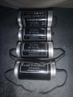
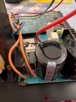
Usually a low resistance feedback network around the output stage would necessitate a rather huge capacitor to maintain the low frequency response and keep the output offset voltage at bay. Since I already did away with the output coupling cap, I also did away with the feedback cap. The result is an output stage that amplifies right down to DC, and thus its own input offset, along with any additional output offsets of the preceding stages. That could lead to inacceptably high output offset voltages across the speaker if left unaccounted for. To take care of this, I have added a little offset voltage to one half of the bridge. It is not necessary to trim both halves to exactly 1/2 the power supply; you only need to adjust one half a little up or down (depending on device variation), so that the idle DC voltage between both outputs is zero. The way that I implemented the offset reference voltage generation is decidedly simple and not very sophisticated, and thus not perfect. It could have been even simpler, had I taken the voltage directly off of the wiper of the trim pot, but the way I wired it instead will prevent the amp from going haywire in case the wiper of the pot fails open-circuit or becomes flaky with age. Note the absence of almost any electrolytic capacitors - there is merely a single 220nF foil cap (C8) to keep the power supply noise from coupling into the non-inverting input of the inverting input stage, and that's all that is necessary, really.

In my prototype I have zeroed the offset at a supply voltage of 19V, and the output offset varied about plusminus 30mV along a supply voltage range of 6V to 30V. This is not optimal and might be fixed with little effort, but it is certainly not problematic in normal use, considering that plusminus 50mV are deemed acceptable. I did not test it, but I suspect that adding a fixed voltage reference might add some minor nuisances, like increased noise or thumps. Speaking of thumps, the behaviour of my prototype is not impeccable in this regard. It does produce an audible thump at turn-on and a less audible one at turn-off. They are still a little annoying, but far from the membrane-moving loud thumps you'd expect from a capacitor coupled design and thus much easier on the ears and on the speakers. Of course this behaviour might vary from build to build due to device variations; maybe it's actually possible to match the output stage chips for lowest thump? It is certainly acceptable as it is and I'm fine with it, though. The thumps did not become any louder or more severe during my bench testing, although I varied the supply voltage quickly over a wide range, including hard current limiting and dropouts down to 0V.

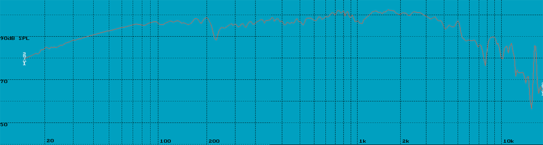
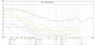
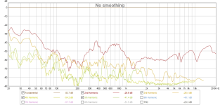
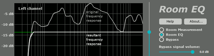
To keep the pickup of mains hum and RF interferences to a minimum, I have opted for a rather low input impedance and added some low-pass filters to the input stage as well as to the output stage. The resulting frequency response isn't ruler flat out to 20kHz and beyond anymore, but on the other hand it won't amplify the switching noise of the laptop brick all that much, should you choose to use one. Of course you are free to change the values to your liking, or leave the filter caps out altogeter. Again, an input impedance of about 1k should be no problem to drive nowadays, where your garden variety smartphone or MP3 player happily feeds 16ohm earphones.

As noted above, I have tested my protoype build with supply voltages in the range of 6V to 30V. 5V is too little already; it will still work, but the output is noisy and distorted. With around 6V as a lower limit, I would recommend the use of two Li-Ion cells in series, for a nominal 7.4V, as a useful minimum. Anything up to 8 cells in series (29.6V) will work, even with a charger connected (8x 4.2V = 33.6V). Anything in between is fine, too, like one or two (or three) 9V batteries, 12V or 24V lead-acid batteries with or without charger connected (11V to 14.4V and 22V to 28.8V), 12V wall warts, 19V laptop bricks, you name it. On the upper end of the spectrum I would set the limit at around 34V, depending on the opamps you're going to use. My intention was to hook it up to a 24V PV solar island system, which can see voltages approaching 30V during the day, and it will easily survive that condition. Some more headroom might be squeezed out by adding some zener pre-regs to the opamps and limit their voltage supply to a save value, but then again you'd probably just hit the current limit of the chip amps sooner and have nothing gained in the end.

single-supply-bridged_proto.jpg

My prototype build uses TDA2030A as the output chip amps. Anything similar like the LM1875 should work as well. Gain is configured to 11 (or 20.8dB non-inverting) and should be stable. If not, you can increase the 1k's around the output stages a little, up to around 2.2k I'd say. The feedback networks of the two halves of one bridge channel do not have to be matched at all. They may actually be wildly different and then merely impose a limit on the overall output voltage swing; they won't add harmonic distortion, as described by Douglas Self in his book on power amplifiers.
For the other opamps I have used three of the four sections of a TL074. My next prototype will be a two-channel stereo PCB and thus need two more opamps. I am planning to use a TL074 again for the input stages, and an additional 741 for the rail splitter. Yes, you read that right: a seven-forty-one, in a design from 2023! Since it won't be tasked with any actual audio duty, can deliver more current than the TL074, is cheap and ubiquitous (and I still have some in stock), that should be a fairly good choice. Again, feel free to substitute your own here, as long as it's unity gain stable and can deliver some current.
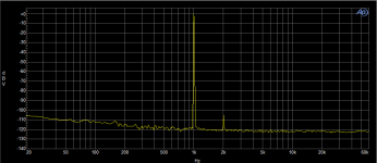
Powered with 19V from a lab supply, the prototype idles around 40mA and didn't show any traces of oscillation connected to several different speakers.
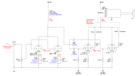
LTspice schematic attached.

Attachments

  • Like
Reactions: Captain B

RCA lineout to Balanced input - Arylic Up2Stream Pro to IcePower 200AS2

Hi all,

I've been reading a lot of posts in there but couldn't figure out my issue - Project is combining Arylic Up2Stream Pro (https://www.arylic.com/products/up2stream-pro-receiver-board) with an IcePower 200AS2 amplifier (https://icepoweraudio.com/buy/as-series/200as2/)

I thought it was going to be a simple matter of connecting wires together but I've discovered the world of balances input (XLR and everything) with the Icepower inputs.

I've seen some schematics online about XLR -> RCA but I keep getting a static when trying with the cables.

Has someone already used these two components together ? What am I doing wrong with the input.

these are the cable coming out from IcePower input.

PXL_20230601_045555734.jpg


Thanks for the insights.

Amp picking up laptop noise

Just got me a Crown XLS 602 used at a price I couldn't resist, sounds great but when hooked up to the laptop which is 90% of my music, picks up lots of noise. I know the noise comes from the crappy laptop PS, but I don't get any noise with any other amp or any other combination amp/preamp other than with the Crown. I've used other Crowns in the past with no issues. Grounding everything and using different outlets doesn't help, also tried different DAC's.
Projects by fanatics, for fanatics
Get answers and advice for everyone wanting to learn the art of audio.
Join the Community
507,714
Members
7,885,582
Messages

Filter

Forum Statistics

Threads
406,105
Messages
7,885,582
Members
507,714
Latest member
sjun1019