Restoring a Woodstock SA4000

So did one stk amp. Did two chip amps.
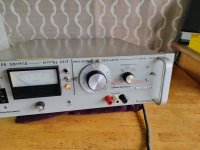
Was at friends shop and he had this crappy looking woostock sa4000.
He sold it to me for 10$.
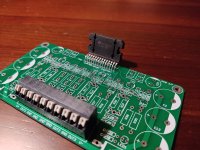
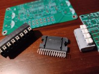
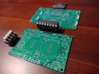
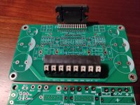
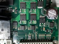
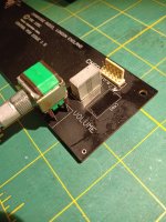
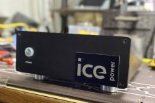
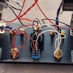
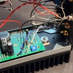
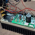
I purchased it because I loved the sound. It sounded just like my dads akai amp from the late 70s.All I cant tell you is that it uses 4x 2N3055HV transistor which seems quite common so I am hoping that I can fix it even if I dont have the schematic.
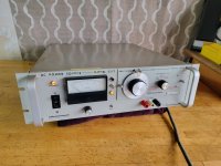
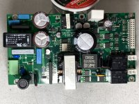
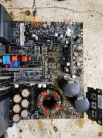
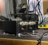
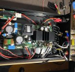
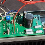
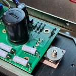
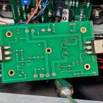
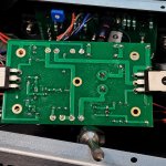
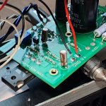
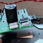
Starting from the power supply. There are 4x 1000uF 35v caps. All are bulged.
Simple question should I replace with the same or should I got with larger values.
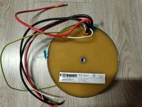
i.e. how about 4700uF 50V. Is there a reason why they used lower values ?. Like maybe lower ESR ?. The Transformer is a 24-0-24 unit.

  • Poll Poll
Beryllium expanded usage?

Favorite ‘Diaphragm’ In Types of Tweeters

  • BE Diaphragm (Bliesma Narrow or SS Illuminator Wide Surround

    Votes: 2 9.5%
  • AMT (Mundorf, Others, ‘Accordions’

    Votes: 2 9.5%
  • Ribbon (RAAL, Others)

    Votes: 5 23.8%
  • Silk, Textile Type

    Votes: 3 14.3%
  • Aluminum Magnesium Dome “Family”

    Votes: 0 0.0%
  • Electro\Magneto Stat

    Votes: 5 23.8%
  • Ring Dome

    Votes: 1 4.8%
  • PEI, Carbon Fiber, Mylar ‘Plastic’ Dome

    Votes: 0 0.0%
  • Compression Driver Horn Metal Or Other Materials

    Votes: 3 14.3%
  • Cone Driver

    Votes: 0 0.0%

Why is there not at least a 6” BE midrange? Is it too brittle? What about beryllium formers? Apparently it had amazing temperature related properties? Is it magnetically inert enough? The BE former could theoretically be literally part of the BE dome or cone (shape and contours and thickness is also important but there’s a company in LA called LA Guage that has extremely impressive abilities to mill it and a thin dome with any thickness and an extremely thin former could probably also be worked out but those are so thin i’m not sure if humans can machine .001mm or whatever it is either way as a number of stiffened foils which must be possible, this could change things what’s going on? I know how lethal it can be but this clip shows some great promise

California Instruments 251T 560-2222 AC power source Invertron 67.5V 135V 270V -- NH USA --

PICK UP NH USA
$100 cash

I don't know anything about it.
Thanks for looking 😆 👽

Attachments

  • 20220922_100319.jpg
    20220922_100319.jpg
    443.6 KB · Views: 120
  • 20220922_100321.jpg
    20220922_100321.jpg
    323.1 KB · Views: 122
  • 20220922_100324.jpg
    20220922_100324.jpg
    416.9 KB · Views: 108
  • 20220922_100328.jpg
    20220922_100328.jpg
    441.4 KB · Views: 106
  • 20220922_100350.jpg
    20220922_100350.jpg
    568.3 KB · Views: 112
  • 20220922_100402.jpg
    20220922_100402.jpg
    550.7 KB · Views: 107
  • 20220922_100406.jpg
    20220922_100406.jpg
    493.5 KB · Views: 103
  • 20220922_100415.jpg
    20220922_100415.jpg
    543.3 KB · Views: 100
  • 20220922_100431.jpg
    20220922_100431.jpg
    401.2 KB · Views: 119

KEF 104 ab crossover rebuild service?

I have a pair of kef 104ab that need the crossovers re-capped, is there a link to a service or person who will do this? I would provide the crossovers and the falcon re-cap kit of replacement capacitors. And while I'm asking for help, could someone reply with a link to the correct Falcon capacitor replacement kit? I am not able to navigate their website for some reason. Thank you for the help!

Tuning speakers to specific music genre

In the DIY speaker world, people usually design their speakers to achieve a flat frequency response. I wonder if there are people who tune their speakers specifically to certain kinds of music genres.

I've seen vintage JBL speakers modeled "L222 Disco". I think they designed this model to play very well with disco music. What do you think about it?

And how do we tune the speakers to match the characteristics of each kind of genre? I'm not sure if we could follow the "EQ" curves offered in some modern or digital audio equipment. Some music genres need a "V" shape on the measured frequency response; some need "W" "M", etc. Lol

Have you ever listened to the speakers that are specifically tuned to a kind of music, as described? What models? How do they sound?

Tesla Siemens Telefunken Toshiba ECC802S E83CC gold pins 6AQ5 EL803S E283CC

In sale are these tubes

Tesla ECC802S – 8pcs 30usd e.a.

Tesla E83CC Gold Pins – 4pcs 50usd e.a.

Tesla ECC803S – 1pcs 50usd e.a.

Toshiba 6AQ5 – 4pcs 20usd e.a.

Telefunken EL803S – 3pcs 30usd e.a.

Siemens E283CC – 4pcs 20usd e.a.

Attachments

  • 6AQ5.jpg
    6AQ5.jpg
    261.7 KB · Views: 141
  • E83CC Gold Pin.jpg
    E83CC Gold Pin.jpg
    198.7 KB · Views: 152
  • E283CC.jpg
    E283CC.jpg
    228.4 KB · Views: 148
  • ECC802S.jpg
    ECC802S.jpg
    212.1 KB · Views: 159
  • ECC803S.jpg
    ECC803S.jpg
    58.5 KB · Views: 150
  • EL803S.jpg
    EL803S.jpg
    319.5 KB · Views: 139

Stupid question on woofer recones

I have some Altec 803B woofers that were more recently reconed with the modern 035400 cones. Trying to figure out the right cabinet, but I notice there’s quite a difference in Vas. The original 803B/416A had a Vas of about 1050, whereas the later Altec 416-8B seems to be about half that. In my mind, I would think that Vas follows the cone, but I’d like to hear from those knowledgable on the subject.

I tried to measure the Vas by adding weight, however, I don’t have signal generator that goes below 20 hz at the moment. The fs of the woofer I tested was 22.3 hz, so I could only add the weight to get to 20 hz, which ended up being 16 grams, probably not enough for an accurate measurement…I got about 75 Vas which doesn’t seem possible.

So, if it’s obvious that Vas follows the cone, I’ll go with that, otherwise I might need to buy a function generator.

Thanks in advance!

Choosing a woofer for 3-way sealed, DSP-powered

Preface
I have a 2-way sealed speakers with 10" midbass, which is better suited for midrange and took a lot of DSPing to get good response down to 50 Hz. I cross to sealed 14" subs at 100 Hz when I want to. I was wondering if I could have better bass quality, not just SPL, by adding a woofer for 50~200 Hz range (presumption: yes). I'm using 3-way DSP plates in existing speakers to drive the midbass in BTL-mode, but I could have the third channel to drive a separate woofer instead. I have some conditions: 1) I was hoping a relatively small box (less than 50 liters) to remain stand-mounted (on the subs) and low floor footprint. If I have to go floor-standing, the solution would probably need to be able to ditch the subs. 2) I hate port noise and muffled response below port tuning frequency, so sealed it is. As are my current main speakers and subs.

Beef
I've read through many forum threads and hundreds of 12-15" woofer specs (not joking), and started modeling with VituixCAD. I noticed that virtually any 15" is easy to DSP to 50 Hz or lower response, even with way too small box and completely ignore any EBP and Q-factors. With 12" the box size probably fits my target box size external limitations, but takes a bit more effort to get to 50 Hz. My current 10" woofers have a fairly large box for sealed alignment, so this experience does not directly translate to sealed in a small box.

The real questions are:
1) How to choose a good-sounding woofer for this frequency range, which T/S parameters are meaningful to predict transient quality etc?
2) Will a small, sealed box hurt woofer sound quality, if it had T/S params more suited for bass reflex operation (like high BL, Qts<0.3, high VAS and so on)? This essentially means 12" vs. 15" in my case.
3) Should I just aim for 20 Hz with a 15" or an 18" in a proper box and ditch the subs?

A funny thing is that I currently have a 3-way system as a whole and would be just trading the subs for woofers and cross higher. But I don't think that would be a downgrade and also going 4-way system as a whole is tempting. The full stack could get quite tall, but I can go creative with element placement when they are all in different boxes. If the prototype fulfills expectations, I'll probably make new cabinets to house all three divers.

PS
My room is largish and quite free from bass-modes. I'm using DSP-plate amps and a DSP-preamp, so almost any form and amount of DSP is a possibility. I also have good amps lying around that I could use for power. I'm fond of Eighteen Sound products and hope to find a solution there.

2-way with full-range and low XO question

I’ve seen and heard plenty of 2-way speakers where a full-range driver was crossed over with a tweeter or super-tweeter, but not very many where the full-range driver is paired with a woofer. Is there a reason for this? The drivers I’m looking at are the Tang Band W5-2143 and the SB Acoustics SB34NRX75-6 with a LR2 @ ~400Hz (using a miniDSP for XO filter and frequency response tuning). My primary concern is that the full-range Tang Band driver might be taking on too much of the music and will be unable to keep up with more complex passages. I plan to keep the Qtc of the Tang Band in the vicinity of .5, (1 cu ft) which should help. The SBA woofer will likely sit around a Qtc of .8. (~2 cu ft). But will that be enough to reproduce complex passages without loss of detail? I don’t want to unintentionally restrict my listening library. For… reasons, I need to keep my cabinet down to ~3 cu ft, total. Pros and cons?

Upcycled AKAI AA-1020 with Arylic Up2stream Min and Arylic DAC board

Hi all, I recently startetd upcycling beautiful 70's hifi components making them suitable for today's daily use.

I internally upgraded an AKAI-AA-1020 receiver with an Arylic Up2stream Mini Streamer (which includes WLAN, Bluetooth and DSP). An additional Arylic DAC board improves the sound quality of the streamer. A Mean Well PS-05-5 power supply powers the streamer and is internally wired to turn on and off with the AKAI. The streamer is internally connected to the AUX connector on the AKAI. The AKAI is now a streaming, WLAN, DSP, and bluetooth capable receiver, making it a complete, stylish hifi system. For example it can be used with Spotify and many other streaming services out of the box.

I am thrilled with the sound I get out of the AKAI with the Arylic Streamer using two old Phonar Laser 200 speakers 🙂. The improvement of the sound by the additional DAC board is small but fine. The highlight and crucial for me is the integrated DSP. I took measurements with Room EQ Wizard and a UMIK-1 microphone and then made a few corrections via EQ in the ACPWorkbench softare from Arylic. This brings a significant improvement in sound quality. In the current situation I could tame too much highs from the speaker and some exaggerated bass frequency areas which are rather room and positioning than speaker problems.

I did some other projects which are a little more radical in the sense that I took old and defect vitage Hifi components to not add but to replace their functionality. I rebuilt a Kenwood KX-400 tape deck and a Fisher FM-7700 tuner into standalone Hifi systems by integrating a bluetooth capable amplifier with respective power supply. If I find the time, I will also do a post here.

Components used in this project:
Streamer: Arylic Up2stream Mini
Arylic DAC Board
Mean Well PS-05-5 power supply

This is my first post here. Are such projects interesting to share? Is the level of detail adequate?
Besides some more stuff already done, I also have some upcoming projects with some nice gear from Kenwood, Luxman, Nikko, AKAI, Technics 😊

P.S.: I am living in Hamburg, Germany, Feel free to contact me when such upcycling projects are interesting and when you would like to take a closer look and listen.

20230406_213503.jpg
20230415_143320.jpg
20230415_154327.jpg
20230415_182627.jpg
20230415_183353.jpg
20230416_212132.jpg

2.5 way crossover too low?

Hi all, I have been playing around with 2.5way crossover design. I am relatively happy with my desired flat modeled response. But, I am a little concerned with the crossover point for the lower driver. It crosses the tweeter at ~1110hz. The Fs of the tweeter is 710hz. This is a 2nd order lowpass, so the crossover should be no lower than 1420hz for this tweeter. However, this is a 2.5way design, so I am wondering if I am safe since the lower drivers lower cross won't be an issue since it is at much lower spl, and the higher driver crosses at 1646hz, which well above that 2x rule.

Any thoughts?

1675533974694.png

Sound change because of re-glue

The dust cap on one of the woofers of my ADS L620s was damaged by a kid. I then sent the woofer to the repair shop. The technician had removed the moving parts of the woofer and fixed the dust cap by pushing the dented dust cap from the back. Then, re-glue the moving parts—the surround and the spider—to the frame.

I received the woofer and noticed that the sound of that woofer had changed! I had rotated the balance control between the left and right channels to compare the sound side by side. They were indeed different.

I told the technician, and he insisted that he hadn't changed any parts at all, just re-glued it.

How does this happen? And how do I get the sound back to the way it was?

Switching the DAC display on the streamer main Touch Display

Hello,

In my new network Streamer project, based on windows mini pc, I would like to integrate a quality DAC based on ESS 9038pro.
From my point of view, the best solution is to buy a stand alone S.M.S.L DAC. su-9, disassemble it and integrate the components inside the large case of my DIY steramer 2.0. even if the DAC board, display, button controls, remote control and USB module are on the network.


My problem is that my Streamer already features a 12.6” 1980x515pix wide touch display.
Is there a way, even a complicated one, to drive and/or switch the DAC display to the 12.6” display, even in PIP?
Thanks

For Sale 4 ECC801S Telefunken

Hi all. I am selling my 'audio treasures' because my DIY audio time is finished. And years built and collecting audio stuff.... So, I buyed these tubes ten years ago and never were connected. Boxes are in bad state, but tubes were measure yesterday with values that are shown. I used utracer 3+ for checking.

ecc801s_1.jpg


Next is how I measure

how_measure.jpg


ecc801s_2.jpg


Next are results form utracer
ecc801_tfk_1_1.jpg


ecc801s_tfk_1_2.jpg


ecc801s_tfk_2_1.jpg


ecc801s_tfk_2_2.jpg


ecc801s_tfk_3_1.jpg


ecc801s_tfk_3_2.jpg


ecc801s_tfk_4_1.jpg


ecc801s_tfk_4_2.jpg


This is my reference data
ecc801s_reference_values.jpg


Well, I can sure that I did use never, but these are NOS and I do not know how were used before. Results from utracer are very good, with numbers 1 and 2 almost perfect and 3 and 4 a little down of 100%.


I am selling for the same they cost me years go, around 270 eur the four tubes + shipping cost + paypal fee.

Best

Dayton RS28AS-4?

I know these are no longer available and not very relevant anymore, but... I have a line on a pair locally and was curious as to how they compare to the non shielded version? Everything I could find was either on the A or F, and it seems as no one has used the shielded version in any projects that I could find. Is this because the shielding is simply not necessary these days? Or was there something inherently better/worse between the non shielded/shielded?

For reference, I'd like to build an MTM with a pair of B&C 8BG51s and SEOS8, inspired by Pete Schumacher's "Home/Pro 8" 2-Way" project. So the big question(for me) is if these would be just as successful crossing in the neighborhood of 1-1.1kHz?

Thanks in advance.

ESS AMT-1 vs Dayton AMTPRO-4 vs GRS PT6816 - any thoughts?

After building a large Synergy horn prototype with a 1.4" driver, the next one will be AMT/Planar based. I have a pair of the ESS AMTs, also a pair of GRS planars - but I wonder if it was worth trying the Dayton AMTPRO-4, too.

I really like the ESS AMT, but it is really a pain to mount a horn to it. The GRS planar is not bad at all, but lacks a bit sensitivity compared to the ESS. The AMTPRO-4 could most probably be easily fitted to the same horn as the GRS with a different adapter, since the dimensions are quite similar.

Have you ever compared/tested the AMTPRO-4 to any of the other two units?

Alk horn crossover

The AP12-xx series networks are designed to operate with the Klipsch K33 woofer which represents an impedance of 6 Ohms in series with 1 mHy voice coil inductance. The inductance becomes part of the filter leaving the 6 Ohm component to become the actual resistive load impedance seen by the amplifier. It will operate in a 2-way system or in a 3-way system with the addition of a separate squawker / tweeter crossover such as the ES5800 from the 4 or 8 ohms amplifier connection.
$150 OBO

Attachments

  • 494501FC-C1D5-42B1-8371-77FC8D629ED6.jpeg
    494501FC-C1D5-42B1-8371-77FC8D629ED6.jpeg
    828.6 KB · Views: 138

Wharfedale Super 10/RS/DD cabinet advice

I'm having a clear out and found a working pair Wharfedale super 10rsdd which I though I could sell.
I tested them to make sure they sounded right and I was suprised how good the were without a cabinet.
I'm wondering whether i should keep them
I have seen the design in the publication below which shows a cabinet 28x16x10 inches
I can live with the size but I don't like the shape, can I alter the dimensions whilst retaining the cubic volume
without affecting the performance?
I was thinking 24" high 13" wide and 14.3" deep with a 13" x 3/4" slot at the bottom and moving
the speaker unit to the top of the cabinet.
The other thought was would a tuned port tube sound better than a thin slot?

http://ukhhsoc.torrens.org/makers/Wharfedale/Wharfedale_cabinet_construction_sheet_October_1965.pdf

For Sale B&C 12TBX100-8 x2 (UK)

For sale two B&C 12TBX100-8 subwoofer drivers. There are some (minor) blemishes on the cones I think caused by paint overspray. £300 for both. I can post for an additional £20 (to UK) or collect from Warrington WA4.

Attachments

  • 1.jpg
    1.jpg
    440.7 KB · Views: 114
  • IMG_20230529_131201457.jpg
    IMG_20230529_131201457.jpg
    526.1 KB · Views: 100
  • IMG_20230529_131204175.jpg
    IMG_20230529_131204175.jpg
    580.4 KB · Views: 109
  • IMG_20230529_131224537.jpg
    IMG_20230529_131224537.jpg
    626.6 KB · Views: 101

Celestion AXi2050

I have a pair of Celestion AXi2050 for sale. These are in perfect working condition having only ever been used with a low power SET amp. They have never been opened. There are a few small marks on both drivers and a scratch on one driver (see photos). I'm going to put them on ebay soon but I'm open to offers on diyAudio for a week.

I also have a pair of prototype 300hz ATH horns for sale - 1m diameter . They are not pretty (well quite pretty) but will show what the AXI2050 can do (see response). Please DM me for more info.

Shipping from UK.

All best,
James
IMG_20230523_135807.jpg

Attachments

  • IMG20230523130309.jpg
    IMG20230523130309.jpg
    557.1 KB · Views: 182
  • IMG20230523125327.jpg
    IMG20230523125327.jpg
    581.6 KB · Views: 187

15" Mid-Woofer suggestion

Hello!

I am looking to incorporate either of the mid-woofers for a 2-way project.
Which one do you recommend, to be crossed at around 650Hz to a horn CD?
Other suggestions in this price range are welcome.
Anyone with any experience with either of these MWs please share your thoughts.

@vineethkumar01


15" Mid-WooferFaital 15PR400Beyma 15P80Fe/N
Nominal ImpedanceOhm88
Power handling AES noiseW400800
Sensitivity (1 W / 1 m)dB99101
Frequency responseHz35-400030-4000
Voice Coil Diameterin3"4"
MagnetNeodymiumFerrite
Surface AreaSd cm2857880
Resonance FrequencyFs3532
DC ResistanceRe5.15.3
Mechanical Q FactorQms65.5
Electrical Q FactorQes0.340.19
Total Quality FactorQts0.320.18
Equivalent VolumeVas223305
Moving MassMms85.288
Mechanical ComplianceCms240279
Motor StrengthBL16.722.1
Max. linear ExcursionXmax5.757.5
Xdamage15.526
PriceЄ138.87Є236.63
  • Like
Reactions: vineethkumar01

LM4781TA 3 x 35 watt rms amplifier ideal for 2.1 or three way active system

LM4781TA Diy audio amplifier kit for sale 29€ more shipment.
LM4781TA with PCB and connector
If you require power supply, the one displayed here can be supplied the cost is 8€ with connector.
Tracked shipment, shipment to US on request
Payment by paypal
1679767466136.jpg

Attachments

  • 1679767526677.jpg
    1679767526677.jpg
    455.3 KB · Views: 76
  • 1679767466129.jpg
    1679767466129.jpg
    396.5 KB · Views: 84
  • 1679767466133.jpg
    1679767466133.jpg
    488.5 KB · Views: 81
  • 1679767466124.jpg
    1679767466124.jpg
    506.1 KB · Views: 79

For Sale LM4780 Full diy stereo kitt "supply and pre amp pcb"

LM4780TA Diy audio amplifier kit included power supply PCB 44€ more shipment
LM4780TA IC with PCB more power supply PCB with connectors and pré amp pcb.
Tracked shipment,shipment to US on request
Skematics sended together with articles
Payment by paypal
1679049910530.jpg

Attachments

  • 1668262103195.jpg
    1668262103195.jpg
    398.3 KB · Views: 97
  • 1668262103202.jpg
    1668262103202.jpg
    395.4 KB · Views: 95
  • 1668262045130.jpg
    1668262045130.jpg
    452.6 KB · Views: 105

Repurposing DC motor drive H-bridge as class D amp

Recently I got given a board that was part of an automatic swing door opener. It supplies a PWM'd voltage to a reversing DC motor. The board has a 30V DC power supply rated at maybe 7-10 amps and a discrete 25CN10N H-bridge with L6384E level shifting mosfet drivers. I'm thinking of seeing how well it would operate as a filterless class D amplifier. 30VDC rail should give a little over 50 wrms into 8 ohms. There is no provision for NFB so I'll skip that for the moment. What would people recommend for a suitable IC to provide the drive waveforms. 0-5V needed

Attachments

  • Whole board.JPG
    Whole board.JPG
    614.9 KB · Views: 103
  • H bridge.JPG
    H bridge.JPG
    514 KB · Views: 107

Laptop power brick modification for +/- power supply

I have a few 19.5V power supplies with damaged connectors that I'd like to repurpose for trying out class D amp boards that require +/- voltages. As they are, the - side is connected to earth ground (3rd wire on the wall outlet). I wanted to see if it was possible to make them floating/isolated for the - supply. So I opened one up. It looks to me like this will be very simple.
On the back of the board, there's a D7575 chip.
Back.jpg

D7575PS.jpg

I looked up the datasheet, and found their example circuit, with separate grounds for input and output, separated by a transformer and an optocoupler. The transformers on the board are obvious, and I also found a BL817 optocoupler (circled in red) and a green/yellow wire from the earth ground input to the negative side of the output.
FrontWithGroundWireAndOptocoupler.jpg

If I cut the green/yellow wire, or put a ~megohm resistor in the middle of it, will this be a workable negative supply?

Compact Bookshelf Build - Options / Recommendations

Hi!

Hoping some collective experience may help here. I've looked over every DIY Kit / Design I can find and haven't really found exactly what I'm after. Maybe my Google-Fu is becoming weak.

Essentially I'm after a bookshelf speaker that will work in my space, constraints being;

1. Depth. I'm hoping for 250mm max.
2. Sound good with a wall close behind. So I'm guessing Sealed or Front ported is best
3. Not too entry level. Want a fairly high end sound despite the spatial constraints
4. Be a Kit or pretty thorough plans, I have no speaker design knowledge, but can happily work timber, solder etc.

The closest I've found so far is the Purifi-6R (link #1) design from Troels, and the "Bijou" (link #2) one using Visaton drivers.

Purifi 6R - http://www.troelsgravesen.dk/Purifi-6R.htm
Bijou - https://www.soundlabsgroup.com.au/p/V-5889-Bijou-170/Bijou+170+Speaker+Kit

I don't know about specific drivers etc, and a lot of builds its hard to find people who have done them or any real review on it. So its going in blind for most part.

Be in 4.5x4.5m room, sitting about 3m from them at a guess. Don't need crazy sub-bass, whatever comes out of a decent 5-6" would be fine. And in Australia, I think I can get most parts locally, if not happy to import.

Thanks for any help!

Ben

Greetings - Been a member for a while - first time posting. Mark Levinson 20.6 and 23.5 owner

Hello to all,

Been a member on this forum and others for some time. I usually just look around. I own both a Mark Levinson 23.5 and 20.6 mono. I read with great interest posts from Hans Polak and others as one of the 20.6 is having issues after I repaired it about 4 years ago. Similar issue as before I believe but this time not so simple. Started off with clicking and popping in speaker but now amp protection being activated. Found at least one bad 2.2uf 160v film cap so far. Last time it was one of two matched fets in the steering circuit for the POS_Drive and NEG_Drive. I have isolated the problem to a certain degree but the fix still escapes me. Wish me luck. I hope to solve this myself but may posting here for some more guidance.


Kind Regards,
John R.

I'm looking for a 2.1 50w / 100w bluetooth amplifier board that will allow me to add potentiometers that control volume, tone, crossover frequency.

I really like this board and it sounds like the potentiometers on this one can be moved but it's a delicate operation. Can you recommend something similar that might be easier to work on?

Also, what exterior potentiometers would you recommend, especially keeping in mind that on this particular board, the volume knob serves several functions. Long push controls power and short push toggles between bluetooth and aux in, and of course turning controls volume (surprise!).

Single channel amp board and heatsink from Parasound 5125 teardown - fits 5125 or 2250 left ch

I bought the Parasound 5125 cheap to use as a donor case from a seller who bought it local and basically got ripped off. He told me the amp wouldn't fire up and clicked when turned on but had no lights on the front and nothing seemed to work. I really only wanted it for the case, but did some troubleshooting for fun and figured out that 4 of the 5 amp boards had problems while the 5th seemed to be perfectly fine. The amp was actually going into protect immediately upon powering up but the original seller had opened it up and unplugged all the leads going to the front LEDs and one of the amp boards with a melted FET. After removing the 4 bad channels, I tested the single board to moderate volume levels and it works fine. As I'm tearing down the PS amp for the case and the main/input boards for a Icepower project I thought someone could use the single PS channel board.

I pulled it out of a 5125 where it was one of 5 identical boards, but according to the writing on the board it also fits a 2250 as the left channel.

$40 shipped to the lower 48.

PS ch test.jpg


PS board pic.jpg

OPS complimentary MOSFET IRFP240/IRFP9140 and IRP340/IRFP9240

Hi all,

Have a question here:
If IRFP240 and IRFP9240 are considered complimentary, why is that IRFP9140 actually seems like a better complimentary mosfet?

Looking at the datasheet:
IRFP240, Qg=70, Ciss=1300pF, Id=12A, Pdis=150W, Rds_on=0.18, $2.95, Soa at 40V I=11A/sqrt2=~7.7A
IRFP9140, Qg=61, Ciss=1400pF, Id=-15A, Pdis=180W, Rds_on=0.2, $2.63, Soa at 40V I=8A/sqrt2=~5.6A

Note the Rds_on is 0.18R and 0.2R which is pretty close in my opinion. Also, Qg is 71 vs 61.

Another pair I was comparing was IRFP340 vs IRFP9240:
IRFP340, Qg=62, Ciss=1400pF, Id=6.9A, Pdis=150W, Rds_on=0.55, $5.17, Soa at 40V I=6A/sqrt2=~4.24A
IRFP9240, Qg=44, Ciss=1200p, Id=-7.5A, Pdis=150W, Rds_on=0.5, $4.72, Soa at 40V I=7A/sqrt2=~4.94A

Their Rds_on are 0.55R and 0.5R.

Audiolab 6000CDT rectifier mod - no smoothing cap?

Hi all.

Starting off modding my Audiolab transport to see what more I can get out of it, its great.
Some questions please going into the Project?

Not a lot online about it,
but saw a German site with before and after pics, going along these lines.

STOCK
6000cdt_servo_t.jpg


MODDED
6000cdt_servo_mod_t.jpg


Usual Cap improvements,
but Note the 2 4pin rectifier chips that have been relaced by a Shottkey diode bridge below the AC input cable.
My (limited) understanding is that you'd normally put a smoothing cap in there to avoid ripple and keep DC to board level?

Couple of guys have replicated this mod exactly, and report only improvements in the sound.
2.jpg
New Diode Arrangement on PCB 2.jpg


One guy used 1A, 100V the other used 1A 1000V
Higher voltage rating better to handle potential AC voltage spikes?

Seems a viable way to do things, but whats the story with the lack of Smoothing Cap?
Is this a full Shottkey Bridge, or just a Wave rectifier, that doesnt seem to need a smoothing cap?

Also,
in this application, are superfast switching diodes better, in the nS rather than pS range?


Thanks for any feedback Chaps. 🙂

How to write an ASIO driver

Hello! I would like my device to be compatible with ASIO, so I try writing ASIO driver. I used driver example from SDK as the base from here https://www.steinberg.net/developers/. Managed to build project to get .dll and register it in the system. In foobar2000 new driver can be seen. When it is chosen as output, audio stream is being played back, but no sound can be heared. I have read SDK documentation, but do not understand what exactly I should change / add and where.

Can someone help with ASIO driver or advise something?

For Sale BMS 4550 compression driver, matched pair

Bms 4550 compression driver. New, only one opened. Never used. Small imperfections in the foam that covers the plate. See pictures.
The price for the pair is: 250€
European shipping is 25€, international shipping is 55€, if you want insured shipping please ask for price. Payment by PayPal, satispay or bank transfer in advance.
my email is franco.cauda@gmail.com

Attachments

  • IMG_9609.jpeg
    IMG_9609.jpeg
    544.7 KB · Views: 226
  • IMG_9610.jpeg
    IMG_9610.jpeg
    455.5 KB · Views: 121
  • IMG_9608.jpeg
    IMG_9608.jpeg
    638.1 KB · Views: 111
  • IMG_9607.jpeg
    IMG_9607.jpeg
    473.5 KB · Views: 109

Bose Companion 5 Speaker Troubleshooting

Hi Guys, please help me, my Bose Companion 5 right speaker channel is not working.
Any help troubleshoot?

Attachments

Mark Audio CHP-70 BR cabinet options

Hello! I'm new to full range speakers and am considering building a pair of bookshelf FR speakers using the CHP70. I see a couple of designs available from the Mark Audio website and madisound but hoping for direction while I choose which to try. Links here:
CHP-70.2 vented box standmount
and
Fenlon 70CHP:
and

Golden Ratio vented box

I realize the low end of a small driver is limited but I'm hoping for "as much low-end" as possible while still sounding good. So I assume that puts the GR box would be best with its 11L volume.
Regarding the port, is there a reason that a port would be on the baffle rather than back of the box?

Thanks for any comments!

For Sale Custom B1K Nutube

Item for sale is custom b1k nutube made board, with kosher components (2200uf uhw nichicons for filtration, dale psu resistors, prp resistors, silver mkp capacitors). It is currently in my integrated amplifier build, and it hasn't been on since my new r2r dac was made and paired with burson v6c, so i'd rather it doesn't collect dust and see some bappy hours in someones system. It is coming with meanwell adapter from diyaudio store, marks psu filter, alps pot, as well as another empty pcb with matched jfets in case you want to make balanced version in the future.

Price is 200 euro + shipping and paypal fees.

Screenshot_20230220-191624_Video Player.jpg

20230220_192519.jpg

Seas L26ROY + Seas T35 C002, is it possible?

Hello all knowledgeable DIY'ers,

I have some drivers in my possession that I want to make use of. The L26ROY D1011-04 from a subwoofer build and the Seas T35 C002 from Troels DTQWT mkII.
The DTQWT's have had the mids burnt out and holes poked thru the pulp and dust caps pushed in too hard from little toddler fingers. So they are to say out off commission, but the tweeters are fine and dandy. As I only have built pre designed constructions I don't have the necessary skills or equipment to design my own speakers, yet. So I kindly ask here is if my idea is possible or even a good one? I was thinking about building a 2-way larger floorstander. But I haven't simulated anything or measuered the drivers. Is there a kind soul here in this forum who can help out an aspiring DIY'er?

For Sale Icepower 125ASX2se Amp in Ghent Audio Case

Hello all. I have an Icepower Amp I built few months back installed in a Ghent Audio Case. Its set up single ended and Stereo and is 125W into 4ohm rated. Amp is appx 3 months old or so. Im looking for 225 paypal shipped USA only

Attachments

  • IMG_8830.jpg
    IMG_8830.jpg
    318.8 KB · Views: 135
  • IMG_8838.jpg
    IMG_8838.jpg
    621.3 KB · Views: 112
  • IMG_8837.jpg
    IMG_8837.jpg
    383.5 KB · Views: 114
  • IMG_8832.jpg
    IMG_8832.jpg
    555 KB · Views: 115
  • IMG_7797.jpg
    IMG_7797.jpg
    728.6 KB · Views: 124

Question about rare Kenwood stereo amp

I was able to get a Kenwood MX-5000 for $60, the amp in not working but is in mint condition. I am on the fence about fixing it.
There is not much information about the amp, it was the last stereo amp by kenwood. It has a fan, is a dual mono amp.

what do you guys make of the MX-5000 ?

https://www.hifiengine.com/manual_library/kenwood/mx-5000.shtml

HELP: QUAD FM4 Tuner Background Noise/High Pitch Hiss

Hi guys,

I just acquired a Quad FM4, Q02xxxx, fairly late version. Components inside still looks new, way above my expectation of a 30years old tuner!

I made a silly mistake of not having a serious listening test, all I did is just briefly hook up and tested the sound, stereo receiving, and pre-set store 7 stations - all works, without noticing is there background noise or not, I went ahead to replace the following :

- N1 (with 220n 47ohms RIFA PME290)
- C4, C5; 1000u/50v, Panasonic FC
- C6; 220u/50v, Pana FC
- C57; 470u/50V, Pana FC
- C11, C12, C34; 100u/25v, Pana FC
- C62, C37; 2u2/50v, Pana FC
- C56; 22u/50v, Pana FC
- C63; 1u//1u/50v, WIMA MKS
- T9; 7812, ON Semicon with heatsink
- B1; Varta 4.8v 150mAh

After components replacement, I measure the 12VDC, 30VDC rails, all within specs.

Once everything setup, I notice the FM4 is producing high-pitch noise/hiss in the background. The noises are present for all stations, including the "Tune". It raises as I crank-up the volume of my Q34 - Q909 - Harbeth P3ESR.

I tried changing the aerial (essentially a piece of wire with RF connector), doesn't help. I tried removing the earth cable of the IEC power inlet of FM4, hoping it was the ground loop, doesn't help too.

As soon as I come across this thread posted in DADAElectronic (here), there's this guy John from USA experiencing the same exact symptom I'm having! I thought it was the silver light in at the end of the tunnel! I did all I could to desolder, resolder the caps I replaced particularly - C11, C12, C34, C63, C62, C37.

To my horror, the annoying background noise just don't want to go away. I even tried to put back the old caps, doesn't help too. I tried resolder some soldering points of the board randomly, nothing change, no luck.

I was wondering is this background noise already persist when I get hold of the FM4, or was it really due to the change of caps I did?

Aside of the background noise, the Quad FM4 is really a lovely tuner. Matches very well with the rest of my Quad. I'm quite confident to say it sounds very close to my ex-Accuphase T-105, the later of course has added more sweetness that is absence in FM4.

Nonetheless, I really hope someone who's reading this thread could help me out to get rid of the noise.

Thanks in advance!

Best Rgds,
Alvin from Singapore

Philips 40/25/15 watts amplifier with Universal preamplifier circuit.

my dear DIY brothers

this is regarding a circuit developed by Philips in 1970's. it is a 40/25/15 watts amplifier with Universal preamplifier circuit. it was very popular in DIY groups at that time. it use to give a very good quality of sound, eventhough it was a AC coupled amplifier. originally the output transistors are BD182. but most of the people used with 2n3055.

do anybody have the circuit diagram. i got some printed circuit boards without circuit diagram.

regards
renjish

Amp Camp Amp help v1.8

So I'm pretty new to this, obviously why I'm here, also my first time posting on any forum. I'll try to make this short. Just bought two ACA v1.8 amps to run XLR balanced bridged with switch for all options like default for 18w I think it was for each of my bookshelves. My bookshelves are 8ohms. I have multiple years of soldering experience in FPV drone building. So one amp came out perfect. The other not so well. I looked at other posts here and check that most of my connections if not all are fine. My joints look fine imo. They looked better before I had problems and tried to reflow my solder with more flux. So very strange I accidentally mounted the RCA input connections in the wrong order so I had them grounded at first. Fixed that then boom check biased ran them switch position up bridged for a few hours(realized switch up is not balanced I believe). The third time turning them on low volume all of a sudden I notice one isn't working. This is when I tried reflowing and measuring ohms and voltage as per picture in step 56 in ACA amp build guide 1.6. to see what happened. I understand the very basics of electronics but is quite confusing for me to try to understand the PCB schematic hand in hand to figure out where my problem is. I am thinking maybe someone with more knowledge and experience can come in and save me some headache and time. Here are my measurings:
Bad side(Input A)
Q1: S 0ohms D:3.5k G:6k
R10:2.9k
R9: .5k
Q4 D: .5k
R15(a): 3.6k
R15(b): 3.9k
R5: 4.3k
Q2: S: 3.5k D: .5k G: 4.4k

Voltage:
Q1: S: 0v D: 0v G: 20.2v
R10: 21v
R9: 21v
Q4 D: 24v
R15(a): 0v
R15(b): .6v
R5: 1.7v
Q2: S: 0v D: 24v G: 1.7v


I just measured the other side that plays music and its measurements are right on the money it looks like.

I did other reheating and triple-checking wires and triple checking measuring even though the numbers were out of whack due to what I believe was a really old battery in my multimeter BEFORE they worked. I got the bias close and ran them. I'm thinking it's irrelevant because clearly I have something wrong now seeing that it doesn't work anymore and I have 20+ voltage in places I shouldn't. I will attach photos of the bad channel PCB and any help/tips/corrections/theories/predictions/suggestions would be very much appreciated.

Sorry for the not-so-perfect photos and messy job. I was really hoping I would breeze through both amps with cleanliness but now I just want to figure out what's wrong and have this over with. I'm pretty sure I'm missing a few things I wanted to mention. I also just noticed I posted this in a different category from exploring. whoops

Attachments

  • 20230612_184119.jpg
    20230612_184119.jpg
    582.1 KB · Views: 125
  • 20230612_184135.jpg
    20230612_184135.jpg
    590.7 KB · Views: 122
  • 20230612_184224.jpg
    20230612_184224.jpg
    688.7 KB · Views: 129
  • 20230612_184240.jpg
    20230612_184240.jpg
    758 KB · Views: 125
  • 20230612_184309.jpg
    20230612_184309.jpg
    582.9 KB · Views: 118
  • 20230612_184322.jpg
    20230612_184322.jpg
    680.5 KB · Views: 120
  • 20230612_184501.jpg
    20230612_184501.jpg
    553.4 KB · Views: 124
  • 20230612_184517.jpg
    20230612_184517.jpg
    489.3 KB · Views: 124
  • 20230612_184550.jpg
    20230612_184550.jpg
    602.8 KB · Views: 115
  • 20230612_184554.jpg
    20230612_184554.jpg
    465.7 KB · Views: 137

Cabinet affects on tweeter response?

Apologies up front in case this is the wrong forum or a question thats been answered many times.

Im hoping thre answer is "not significantly" so i dont have to do too much woodworking. Most of what i read is about how cabinets impact the mids and lows.

The tweeter would be supplenting my full-range system, a Thirlmere-R cabinet with chbw70 drivers, which is why Im posting here. it woukd be in its own cabinet, sitting on top 9f the thirlmere-r.

I want the tweeter to help in the 4kHz-15kHz range (i doubt can hear above 15kHz). I'd usd a simple crossover circuit. I can scavenge some infinity emits from another speaker pair that im not too fond of. ive read the emits are excellent tweeters.

i dont want to go crazy here, just add some support on the high end.

Speaker Grills On or Off: Which Method Sounds Better?

Speaker grills are typically designed to protect the speaker components from damage and provide a uniform appearance. However, some audiophiles argue that removing the grills can result in improved sound quality by reducing diffraction and allowing for better dispersion of sound waves. It is recommended to experiment with both methods and listen for any noticeable differences in sound before making a final decision.
  • Like
Reactions: GM

Three TDA7293 in modular schematics with PCB design and gerbers

Just for fun made gerbers for three TDA7293 in parallel (modular) design based on this old website http://buildaudioamps.com/tda7293/

Gain is set to 26dB

Attachments

  • Screen Shot 2023-02-24 at 12.32.11 AM.png
    Screen Shot 2023-02-24 at 12.32.11 AM.png
    34.7 KB · Views: 335
  • Screen Shot 2023-02-24 at 12.25.24 AM.png
    Screen Shot 2023-02-24 at 12.25.24 AM.png
    51.4 KB · Views: 332
  • Screen Shot 2023-02-24 at 12.25.53 AM.png
    Screen Shot 2023-02-24 at 12.25.53 AM.png
    50.6 KB · Views: 319
  • Screen Shot 2023-02-24 at 12.26.03 AM.png
    Screen Shot 2023-02-24 at 12.26.03 AM.png
    46.1 KB · Views: 253
  • Screen Shot 2023-02-24 at 12.26.13 AM.png
    Screen Shot 2023-02-24 at 12.26.13 AM.png
    32 KB · Views: 223
  • Screen Shot 2023-02-24 at 12.26.27 AM.png
    Screen Shot 2023-02-24 at 12.26.27 AM.png
    31.3 KB · Views: 241
  • Gerber_PCB-TDA7293-par-r5.1.zip
    Gerber_PCB-TDA7293-par-r5.1.zip
    48.8 KB · Views: 131

Using Cat6 for a long balanced audio

I need to hook up a subwoofer to the other side of the room (maybe a 30ft run), but I don't have enough coax.

My preamp has balanced outputs so I'm thinking twisted pairs are appropriate. Does this sound like a good plan?

I'll make up an xlr to a cat6a cable. At the preamp end, L+ and L- will go on one twisted pair. R+ and R- go on another twisted pair. And Lgnd and Rgnd go to 2 other wires.

At the subwoofer end, I'll use this simple opamp balanced to single ended converter. Then left and right RCAs to the subwoofer amp, which sums the inputs.

I'm also open to using transformer for the balanced to single ended, but I have a feeling that will be expensive.

balance2single.jpg

DIY 4-Channel (mic) Channels

Hey, I was researching about DIY Audio, and I started wondering about this:
Is it worth it to build a 4-channel audio interface? Or buying a good quality one is more worth it?

Even though I'd love to buy one, in my country many things are very expensive because of inflation, so, I'd like to know if it is worth it to build an audio interface from scratch.

About the inflation, here's basically the difference between U.S prices and Brazil's prices:

Model nameAmazon.com pricesMinimum price in my countryprice vs. Brazilian average monthly income
Focusrite 18i8399.99USDabout R$ 4454 (915USD)about 175.35% of the average income
Audient iD44699.00USDabout R$ 4859 (999USD)about 191.29% of the average income

(Putting the statistics just so you understand our reality)

Thanks for the help! God bless y'all!

Audio Consulting AC line filtering kit - $300

thi sis an AC line filtering kit from Serge... if you do not know his work, he builds mainly battery gear as he feels that DC power from AC lines pollute the signal chain.. so he builds large isolation transformers and wound these MASSIVE chokes for cleaning up the AC lines...

I can't provide support for these, but i can guarantee that they are all in good condition and measure as they should.. this is near scrap price for this much copper, so what do you have to lose?

i think i can get these into three flat rate boxes for shipping inside the USA for ~$80.... if you really want me to ship these elsewhere, I will consider it for an extra $100... they are large and heavy..

I have no idea what these cost new, but I am going to guess that each choke cost more than what I am asking for the entire set... I just do not want to scrap them... he must have put much hand labor into these...

each bobbin is ~7" x 5" x 4"...

thanks!

peace,
jeffrey


IMG_5918.jpg


IMG_5921.JPG


IMG_5922.JPG


IMG_5923.JPG


IMG_5924.jpg


IMG_5931.JPG


IMG_5927.JPG

New Project - tower 3-way with twin 8s

I am in the planning stages of a new active 3-way project which I hope to build over the winter.

I have been curious about the Wondom JAB5 amp from Sure electronics. It is a 4 channel amp, 4 x 100W, with on board DSP via ADAU1701 DSP. SigmaStudio is used to program this little board. The cost for a JAB5 board, a programming board, a 36V power supply, and miscellaneous cables and connectors is about $160, compared to about $600 for a Hypex Fusion FA253. I am expecting the Hypex to be superior, due to the super-smooth nCore amps and the more sophisticated D/A & A/D processes on the hypex. But I am prepared to be surprised.

This will be a 3 way system with 2 woofers, TMWW. 4 channels for 4 drivers. It will be a tower which positions the tweeter at about 42” high. I want this system to use moderate cost drivers, given the modest cost of the electronics. I have a friend who may want to duplicate this design, and he is a bit sensitive to costs. So no beryllium tweeters, no textreme cones, no scan speak illuminators for this project. I am shooting for a driver cost of about $400 - $500 per side.

== == == == == ==

Update 5/07/2022: Construction has begun, and the design has changed significantly since the first post. https://www.diyaudio.com/community/...3-way-with-twin-8s.378223/page-5#post-7016642

Goals for this project
1) Design and build a complex 3 way system using VituixCad simulation from the start.
2) Build and evaluate a system with optimized DI and a smooth even horizontal dispersion.
3) Explore some new cabinet construction ideas.
4) Have a system which is more portable than my existing system.
5) Have a system which can serve as a backup for my main system.

Index

Construction photos:
https://www.diyaudio.com/community/...3-way-with-twin-8s.378223/page-8#post-7048860

Start of Measurement phase (post 167): https://www.diyaudio.com/community/...3-way-with-twin-8s.378223/page-9#post-7058310

Completion of Initial Measurement phase (post 211): https://www.diyaudio.com/community/...-way-with-twin-8s.378223/page-11#post-7065101

Completion of Construction (post 247): https://www.diyaudio.com/community/...-way-with-twin-8s.378223/page-13#post-7085208

Comparison of Simulations to Measured System (post 253)
https://www.diyaudio.com/community/...-way-with-twin-8s.378223/page-13#post-7098334

Final DSP filter (post 260)
https://www.diyaudio.com/community/...-way-with-twin-8s.378223/page-13#post-7103088

Photos of the final project (post 354)
https://www.diyaudio.com/community/...-way-with-twin-8s.378223/page-18#post-7142703

Attachments

  • s20211014_172925.jpg
    s20211014_172925.jpg
    587.3 KB · Views: 1,721
  • BT8-Concept-Sketch-1.png
    BT8-Concept-Sketch-1.png
    14 KB · Views: 864

For sale Troels Gravesen 3WC 10

Due to time and space constraints I am offering this complete set for sale. To complete the loudspeakers, only the housing/cabinet needs to be built or purchased. It concerns level 2 package including tweeters. Kit price at Jantzen is EUR 740. Drivers cost new EUR 350 for mid and woofer per loudspeaker. Total value 1400. Asking EUR 1100 plus shipping.

Best,

Robin
IMG_20230611_101230.jpg


faital-3WC-10-present-1.jpg

Attachments

  • IMG_20230611_101429.jpg
    IMG_20230611_101429.jpg
    328.8 KB · Views: 119

The car thread

A new thread focusing on cars, not just focusing on audio but performance and luxury aswell.

We have threads talking about snake oil and various other things like the weather, so why not talk about our cars too? Sure this thread could be better suited for another forum dedicated to cars but we as a community don't know about each others rides. Hence why this thread exists. Thread also exists to prevent threadjacking of other threads to discuss cars, which occured in the snake oil thread.

If you are on-topic in this thread it means that you are talking about your cars and/or their audio systems. Don't necessarily need to talk just about the audio systems of cars.

BUT, don't make a comment detailing some insane mods which require specialized knowledge that is better suited/served by a dedicated car forum. This is mainly just got to deal with the members personal rides, what they look like, how they perform, etc. Would also like to hear about other members rides, performance, repairs, etc.

I have two rides at the moment. A Ford Falcon AU Wagon with the 4.0L Inline 6 engine and a Toyota Camry Vienta Grande V6. Think I'm going to improve the sound system in the Ford because the Toyota is a bit long in the tooth now and the Ford has 6x9's in the front doors.

Ford Falcon (AU - Wikipedia)

Just some history on the australian variant of the I6:
Ford straight-six engine - Wikipedia
Ford Barra engine - Wikipedia

I would love the V8 engine but I don't want the fuel consumption.
N5t13DK.jpg

Attachments

  • 31-diyaudio.JPG
    31-diyaudio.JPG
    23.6 KB · Views: 849

Help Finding Source of Low Frequency Noise in Tube Phono Preamp

I recently built a tube phono preamp, and I am having a difficult time tracking down the source of low frequency noise (20Hz and below). My overall noise floor is bouncing up and down and peaking around -25dB or so. Per the attached graph, much of this noise is in the low frequency range. You can also see a couple of spikes around 120Hz and 240Hz likely from DC power. The attached plot was taken with inputs shorted to ground at the PCB. I have tried numerous tactics for tracking down the source of the noise, but have failed so far to figure this out. Here are a few additional facts and thoughts below:
  1. It almost looks like what I'd expect to see with a DC offset issue. Though the output is coupled with a 2.2uF/1mOhm RC filter which SHOULD address that issue. I'm not really sure how to measure DC offset on a phono pre or what normal range of values to expect. I have put a multimeter on the outputs and watched the voltage jump up and down. On a stereo speaker output you typically measure with the volume all the way down, but the phono pre does not have a volume control so I'd expect I can't go by guidelines typically associated with stereo speaker output DC offset measurements.
  2. The preamp is built around 3 12Ax7 tubes. Heaters are wired in parallel running on regulated 6.3VDC from 6.3VAC secondaries on my toroidal transformer (Antek). I'm actually running at around 5.7VDC due to some voltage loss in my rectifier bridge - about to replace that bridge with Schottky diodes to get more headroom. Would running heaters just 0.6 Volts below optimal heater voltage potentially explain my low frequency noise issue?
  3. I've tried tapping around with a platstic tool, pushing components, double checking solder joints, multimeter testing capacitors, moving cables around, connecting and disconnecting my star ground points from chassis, etc. None of the tactics I have tried has helped me narrow down the issue. Anyone have other ideas for things I should try to narrow down the issue?
Any help is appreciated! I can provide further details as necessary.

Attachments

  • 2023-06-04-PhonoPreLowFreqNoise.png
    2023-06-04-PhonoPreLowFreqNoise.png
    181.8 KB · Views: 151

Newbie questions about winding transformers

I've bought a pair of mono amplifiers, hoping to restore and modify them slightly. Unfortunately, one has been heavily modified already and the output transformer has been rewound.
I would like to rewind both OTs to make them a matching pair. Besides the task at hand, transformer winding is a valuable skill I've always wanted to learn.

I have had a look around on this forum and also around the web, but information seems scarce on this topic. I have a seen a few videos online and I think I can pull off the mechanical work. The few questions I have regard the theory and the design of transformers:
  1. I'm planning on buying a rather cheap manual winding machine from Amazon. While I'm at it I will buy the enameled copper wire as well. In order to do that, I understand that I need to know the number of turns and max current for the given winding. I understand I can also parallel multiple wires to obtain a bigger gauge, but given my inexperience and cheap equipment, I'd rather avoid that.
  2. I'd like to receive recommendations for cheap winding insulation materials. I'm interested in both scotch tape (I have seen yellowish transparent tape used as insulation) and pressed paper. I'm looking for something that's easy to get and fairly cheap, hopefully available at a local shop. Does insulation have an influence in design choices? (As far as I've understood yes, but I don't know how)
  3. The main issue I need to sort out is designing. I'd like to understand how to design a transformer. I understand the basics of how transformer work, and I would probably be able to compute the necessary winding ratio for a power trafo. Then, I'd need to decide the wire gauge based on the allowed current, the core size, etc.
    Guidance, references or even books on these steps are extremely appreciated. If there is some sort of spreadsheet or tool to compute these numbers I'd happily use that as a safety check before proceeding with winding.
  4. Winding output transformers is a totally different ball game, as I see oftentimes windings are interleaved, and I'd need to understand when and how to apply that technique. The OPTs I'm going to rewind are push pull, so they're at least easier (and I hope more forgiving) then single ended.
I'm going to rewind both power transformers and output transformers, so I may want to start from the first as they seem easier and more forgiving. Sine I'm rewinding all the iron, I can also change the amplifier design quite a bit. Given the amount of freedom I have in this build, I prefer to learn how to design transformers and not receive a pre-made design without explanation. Any suggestion or reference to a guide is appreciated.
If you want to explain by giving an example, my goal would be to produce 2.5k PP output transformers rated for 60w (I don't know the type of the EI laminations and core, I'd still need to measure them).

For Sale Toroidy Supreme Audio Grade V2

Brand new never used .
2 X Toroidy Supreme Audio Grade V2 transformers with mounting brackets.
Specs : 2X13Vac/500VA
Price / piece : 180 Euro
Price / pair : 300 Euro
Europe sale only and shipping cost not included .
Also have 3 pieces of 2X18Vac /800VA same prices

Attachments

  • toroid top.jpg
    toroid top.jpg
    703.1 KB · Views: 313
  • toroid bottom.jpg
    toroid bottom.jpg
    464.8 KB · Views: 327
Projects by fanatics, for fanatics
Get answers and advice for everyone wanting to learn the art of audio.
Join the Community
507,718
Members
7,885,677
Messages

Filter

Forum Statistics

Threads
406,114
Messages
7,885,677
Members
507,718
Latest member
Brano KAntor