Hey guys. I've been trying to get started programming the QCC5171 and since I'm locked out of the website's resources, finding info is pretty tough.
I've made a programming jig that people said has worked for other Qualcomm modules to directly connect it via USB, but nothing shows in device manager and there's no sound when I plug it in. Any ideas on what I might be missing? I have no access to the actual chip datasheet, so I have no clue outside of the module datasheet I was provided by the Chinese company I got it from. Even figuring out what program I should be starting with and how to set it up is proving difficult - but I think the answer to that one is Qualcomm MDE (seems to be where I would write the firmware, flash, and debug).
I have settled on a new mini project consisting of a BMS 12S300 in a very low tuned enclosure... BMS Specifies a 60L container for the given response with 110 mm / 517 mm long (presumably) circular port..
I would like a slot designed port and given my confused state i can't seem to find anyone coming up with definitive calculations for getting the correct port length etc.. maybe i am missing something. I have a rumour in my head the WinISD doesn't calculate specifically slotted ports.. maybe i'm being corrupted by something somewhere else on DIY.
BMS Recommends to use a port length almost half the size of mine and a circular cross section of 9500mm2, again thats almost half as much as my 21840mm2 (6X36X102cm) slot port.
Given the simulated response i just don't think i am getting the SPL i should be getting considering this type of driver... it has a super low FS. I have already tried to get more SPL out of the enclosure by increasing the volume by 8 litres...
I have attached some pictures of the simulated response with WinISD and some pictures of the enclosure... my instinct tells me that the port length is two small in width and too long in its entire length to the back.
The parameters as follows....
BOX = 67.8 L
Tuning Freq = 29Hz
VENTS = 6cm X 36.4cm
Calculated Vent Length = 102cm
1st port resonance 167hz (A bit undesirably low... LPF will be set around this point)
After putting together the box in CAD and calculating the volume displacement with the amp modules am i accounting for the rear volume independent of the port volume? i have tried to balance this with the suggested port length 102cm X width and size to somehow find the balance with a slotted port that will fit in unison with the suggested internal 67.8L.
Are there any subwoofer building experts out there that could at least help me approve what i have done as a valid design? I feel that i am overthinking things when in reality it could quite possibly be a bit more straight forward..
I was idly reading Robert Harley's review from some time back in The Absolute Sound (I wrote for TAS during the Harry Pearson days) of the Wilson Benesch Eminence, which can be yours for $232,000 the pair.
That review reminded me (I had reviewed three or four different Wilson Benesch models when I was writing for Stereophile over the course of 17 years) of something that I had forgotten:
That in many of their loudspeakers, including their TOTL Eminence, Wilson Benesch connects the midrange directly to the amplifier, letting the midrange "Run Wild."
Which means that the midrange (or a woofer-mid--WB's midranges are 7 inches) has to cope with all the bass the amplifier is pumping out, while the roll-off of the midrange or woofer-mid is at the top of its passband is purely mechanical and not electrical.
I recall being told the same thing about big Egglestonworks multi-way speakers.
I also recall being told that the very very nice ASA--Atelier de Synergie Acoustique--2-way monitors had a network only on the tweeter, and that the Dynaudio woofer-mids ran wild.
What I plan to do over the weekend is hot-wire the Eton 5-312 woofer-mid in my current prototype directly to the speaker terminals, with the wire running to the crossover sending a signal to the crossover, but with only the tweeter connected to the crossover.
Obviously, a woofer-mid in this circumstance is different from a "pure" midrange (I recall that WB's midranges use lighter cones than the same-size woofer-mids), but what I am describing is just about the same thing, as far as I know, as the ASA.
Furthermore, when I am breaking in woofer-mids, I run them wild in a literal shoebox (Kuru shoes) as an enclosure, and the upper-midrange performance of the Eton 5-312 so impressed me that I video'ed it! I urge everybody to listen to this: Login to view embedded media
In any event, Kate St. John has a lovely voice and a really subtle musical intelligence, and I give her two albums Indescribable Night and Second Sight my highest recommendations.
I tried to upload the album cover image, but the upload function was not cooperative, sorry.
So, just curious what other peoples' experiences have been, and I will update after I do my little experiment.
I bought a pair of ESS Heil AMTs without realizing quite how heavy and bulky they are. So they don't work for my project but I hate to throw them away. I opened one and took an REW sweep, the other is unopened. You can see the datasheet here: Heil web page. I'll send them to anyone who will pay the cost of shipping and packing from zip code 89523. They are kinda cool...but odd!
Just completed work on the Burr Brown headphone application with the OPA2604.: 1k &10K, giving a gain of about 11. 10K shunted with a 100pF cap. and a 47nF/10R Zobel on the output. Works well with various types of headphones.
Unfortunately, the 2604 is now obsolete, the OPA1688 is recommended as a replacement.
This design relies on the high output current capability of the device, so BEWARE of non genuine parts!
This is yet another antique radio to bluetooth speaker conversion. My dad passed away recently. He has a collection of old electronics that included an old Philco radio. The insides aren't salvageable, alas, so it's a candidate for conversion. I've got a few questions regarding the build (which will be my first speaker build ever).
The interior dimensions are roughly 13.5 x 7.5 x 8". It's got a single 5.5" oval opening in the front. I'm planning to build a cabinet that will go inside of the radio body, and to go mono rather than stereo. Here are my questions:
Given the cabinet size, would you go with a single full range speaker or a combination of speakers?
Based on your answer to #1, what bluetooth amp board would you recommend?
I've just learned about the existence and purpose of passive radiators. If going with multiple speakers rather than a single full range, does each speaker get its own isolated space in the cabinet and its own PR or can one PR work with multiple speakers in the same cabinet?
I'd like to keep the original knobs that were on the radio and in their original locations, but of course their purposes will change. Of course one will be volume, but if you were me, what would you do with the others? Treble & bass? Crossover frequency & bass volume? Something else? (I have 4 knobs total)
I have a Mcintosh MC2105 that had lost power in one channel. I worked on it for quite a while but was was not able to find the problem. I left it with a local audio repair tech for a look. He spent a little time and concluded that one of the OPTs was faulty. Said he found no resistance between the common speaker post and the three other outputs. Likely the output wiring had fused. He had replaced a couple of suspect power transistors but only charged me a couple of dollars for the parts he purchased.
Replacement OPTs are very expensive, if you can even find one. The amp is in good shape cosmetically, so I thought I would part-it-out and buy something else. Before doing so, I double checked the speaker post readings and found little difference between the channels.
I have no reason to think the tech has an ulterior motive: he's generally respected, he didn't make any money for his work, and did not suggest doing further repairs. But, I would like to verity this diagnosis before I start disassembling the amp and would appreciate any advice on how to go about testing it.
I've been banging my head against a power amp issue for a week or two now. I'm converting an old Lowery organ amp (6V6 PP) to a JCM800-style guitar amp, and everything works beautifully until I plug in the power tubes to check for output level. One tube shows twice the output level, and at more than about 10% volume, I was getting doubling distortion. I proof-read my circuit more times than I can count, checked for bad solder joints, dropped the supply voltage by 100 volts (to get about 350 on the 6V6 plates), even tried chanting "Go, push-pull, Go!!" while standing on my head and making Walrus noises (not really). I was almost to the point of totally gutting the power amp circuit and starting over with the wiring just in case there was a hidden issue that I just wasn't seeing. Well, it turns out there WAS a hidden issue, and I didn't need to do a full tear-down to find it.
The output OPT primary winding has orange-ish colored leads and a single blue-green lead. I made the mistake of assuming the blue/green lead was the center tap. it isn't. Turns out there are actually three different colors, but age has made two look all but identical. Testing the transformer showed the error, and I've now got the center marked with some black ink, and all is now well.
Just thought I'd share in case anyone else has had the same kind of experience!
Does anyone have experience digging into a late model Kenwood head unit enough to know whether or not they utilise output protection in the form of capacitors?
Am wondering about the redundancy of possibly having both in the head unit and amp, don’t likely need both.
I’ll provide detailed technical discussion and measurements, with plenty of time to listen to music, enjoy conversation, and geek out with your fellow audiophiles.
LOCATION: Oak Park, Illinois (a stone's throw from the city of Chicago)
DATE: 25 June 2023
TIME: 2-5pm
- Message me privately to RSVP and get street address -
The F4 is up and running since a couple months, it took a while to get it assembled but it was faulty, bad soldering, can tell that something went wrong and in the rush to send to me didn't even bias it... whatever, it got fixed, anzi, upgraded and now is in fully working conditions.
At this moment in time I am running it with my ancient Audio Research SP9 whose 20db gain don't really make it, I had a BA3 assembled but it needs some fine tune which is not gonna happen any time soon, on paper the gain should be plenty to drive the F4 but I am already looking forward at how to entertain myself next winter, actually before going dual mono route by building another F4 and bridging the one I already own (won't know how to do that but not this the thread about it) I wish to either mod the BA3 with twin output or to build another high gain preamplifier with just volume control and single or max dual sources, how about the Aleph 1.7, what's the output gain and what about it being coupled with the F4, anybody got the duo?
Hi everyone,
I try to repair my beloved Revox a78.
The right channel power transistors (2N3055, Q505 and 506, board 1.078.115 on the schematic) keep blowing when I power the amp.
The main fuse is too strong, it doesn't blow.
100 ohm R511 or 512 catch fire...
I measured every pin of both power amp board sockets and every voltage or resistance is close to ideal value.
I tried switching the boards, and it always blows on the right channel.
If you have any idea, or general advice in methodology it would be greatly appreciated.
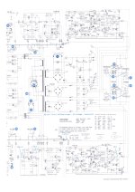
Schematic is attached to this post.
Sorry for my crude hand drawing - I am posting from my cell phone.
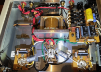
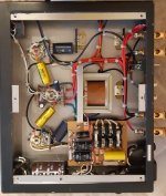
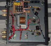
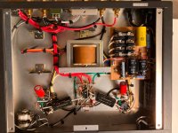
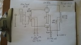
The input is 10-step autotransformer attenuator, followed by transformer phase splitter. The 3D6s are independently biased by Li-ion cells whose voltage can be finely adjusted from 3.2 to 4.0 V. 3D6 filaments (connected parallel) are powered by a NiMH cell, which is automatically recharged when the amplifier is off (charger and it's connection are not shown). Filament battery switch is ganged with power switch. The choke between primary CT and B+ serves as CCS, ensuring strict Class A differential operation. The choke is sectionally wound (to reduce winding capacitance) on 2-bobbin nanocrystalline C-core; it is a custom job. Solid state CCS can be used instead, but choke sounds better. Depending on the source signal level, the output power is 50-100 mW. The amplifier is intended for the Sennheiser HD650 phones.
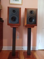
Just updating this old thread. I was completely disappointed with the performance Audex drivers so I gave up on this project and gave the drivers away. I decided to explore in a new direction for me. I've always used ribbon or AMT tweeters with metal woofers in mostly 3 way designs. For a complete change up I decided to design a 2 way with a fabric dome tweeter and a paper woofer. I understand this is a very common approach, but new to me. I will be creating a new thread in the near future but here a a sneak preview. A gated frequency response measurement and a photo of the completed speakers with the grills off.
I'm planning to use up some drivers I have to design a 3 way to give as a gift. I'm trying not to buy too many more drivers because I have too many now. Here is what I have to work with.
2 Audax HM170Z0 aurogel 6.5 inch mid-woofer. 8 ohm 91 db
2 Audax HM130Z0 aurogel 5.25 inch mid. 8 ohm 92 db
2 Audax HM100X2 poly 4 inch mid. 8 ohm 94 db
I think the 6.5 and the 4 inch would be best, but one of the 4 inch mids has a 1 inch crack in the cone and I don't see a way to fix it. I'm concerned the 5.25 inch mid is too big to pair with the 6.5 inch mid woofer. These seem to be high quality drivers and are from the same product line. I also have some poly cell drivers from some scraped Infinity RS8B that I might try. Ultimately I might have to buy a pair of mids and tweeters and use the 5.25 an the poly cell for some two ways.
Hello from Bavaria/Germany,
my name is Stephan and I just want to introduce myself. I've been building tube amps for a while now and as a beginner I'm always looking for valuable information. As a second project I would like to build a small amplifier with the 1626 tube, which is often mentioned here in the forum as "Clementine". I'm definitely very excited to see what I'll find here.
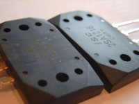
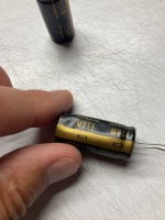
i have purchase from a german company a lot of 2sc2922 and 2sa1216 transistors. the producer is ISC (http://www.iscsemi.cn/).
but the 2SC2922 looks not real and original !
When you look on photo the surface of all 2SC2922 are have
sharpening traces on the surface. It looks like, that all 2922 are get a new label.. The 2SA1216 are smooth like a baby's bottom.
The metalplate of the 2922 are different then the 1216. The Plate of the 1216 has corners cut off from 45 deg but the corners of metalplate from the 2922 are rounded. Then the plate of the 1216 are polished and smooth. from the 2922 are a little bit rougher.
then the font of the labelprint are different. Look on picture isc2.jpg. The font of the labelprint from 1216 are bigger then the print on the 2922 and its a little crooked.
Know everyone about ISC and hear about counterfeit transistors of this company ?
Wondering if someone in Denmark can help with a small transformer order from Dantrafo...need a small dual 120 primary / dual 6.3 secondary transformer - item number DT2010061...still waiting for the company to respond...
PM me if you can help get this order to me...I am in west Sub of Chicago...
Is it necessary to make the "checkout" after I have made a replacement of the output transformers in the Tse?
I Want to make a change from Lundahl Ll1620 to Ll1620-am output transformer? Or is it OK just to make the replacement?
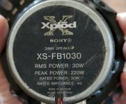
Recently I was given permission to make a home theater in my uncles house however I was told not to exceed $600 and use the old speakers he had. I am planning to purchase a Denon AVR-S760H (Renewed) and a PJ20 Projector. These two come out to $500. and $50 for the screen. I'm left with $50 and these speakers he has at home; Bose Lifestyle 5 Music Center (5.1), Bose 108516 J x4, and Sony XS-FB1030. I want a 5.1.2 setup I read I should use the drivers and make custom boxes (My uncle has a wood shop so the boxes are free). I'll put the picture of what I have. I also came across the use of crossover or DSP. I would appreciate any help on what I should do and which drivers put together for the front, center, surround and heights.
Also. My Room is 16.5 x 14 ft. The screen will be 100-120" on the 14ft side. There will be 2 rows of seats.
been looking to get into electronics but having a issue finding the right entry point. those old kits from radioshack look so good but they are no longer in production. looking to do a HPA or a amp from here
I redesigned a LM1875-based guitar amp that I'd previously made with a few changes as it popped on turn-on due a small issue.
I redesigned the circuit with a few changes and had them made. I've populated the circuit, put it inside a new enclosure and used the same SMPS (Meanwell LRS-36-100) as I did for the original. When the amp if turned on, I'm met with a lot of noise and barely any output from the amp itself. Whatever I do get out of the amp seems to distort extremely easily. Below are a few issues I've noticed -
Noise / Hum (White Noise) without input connected. Input / Output Jacks are Cliff and the input is shorted without connection.
Increased noise with an input connected (This is due to a ground loop, but I'm using the same setup as was previously used without any noise)
Turning the volume pot changes the amount of noise, but also at times causes the noise to increase until it gets unbearable.
Probably unrelated to the noise, but the mute/delay works for power up, but the output cap's supply collapses before it de energiese and causes turnoff pop.
a few things I've tried -
Changed the PSU board to the old one that had a regulator for both the opamps and the amplifier.
Soldered a second board up to make sure it wasn't an issue with a component.
Tried different power socket.
Does anyone have an idea what it could be and what my next steps could be? I'd love to probe the power supply, but I only have a DSO Nano V3 which isn't great for measuring ripple.
Ive attached a picture inside the chassis and the schematics.
Hi everyone .
I have a marantz 510 amplifier that I use to make measurements with REW but it happens that about halfway through its stroke, the potentiometer that adjusts the volume stops doing its job.
so I can't turn up the volume to make an optimal measurement.
I don't know whether to change it with an original one or whether to replace it with a different and more performing potentiometer.
if it were better to replace it with a potentiometer of other brands, can you tell me which one?.
what do you recommend? . Thank you .
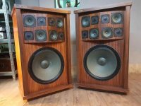
To keep with the same tweeter faceplate, i found the Dayton AMT 8 mini, could be able to be fitted and keeping the aluminum look. I am not sure how the AMTs rate, so a few reviews, seem to praise it.
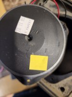
Tweeter controls dont appear to work. I have the crossover out and could i use the multimeter to test it. 3 wipes per control. I labelled them 1-3. Midrange appears to work but scratchy still, even though i have taken both apart, it could be maybe lose connection on the board. I can re apply the 2-26 grease.
I have only the crossover pcb to go by.
To test do put the probe on wiper 1 and 3 and turn the dial
After receiving an Iron Pre Essentials kit from the DIYA store release I began assembling the materials needed for the project. I soon discovered the the Fujitsu-Takamisawa RY-24W-K relays and Lorlin CK1060 rotary switches are not available from Mouser or Digikey and I would need to place two additional orders from two additional suppliers.
So, I decided to order extras of each so that I could, at least, help a few others to be spared from this mild expense and inconvenience. I can offer memebers in the USA either 5 relays and 1 switch for $20 (SE version) or 6 relays and 1 switch (Balanced version) for $22.50. This will be shipped via USPS First Class Mail and save you about $14 compared to ordering them yourself.
The parts should arrive in about a week. Message me if you would like to reserve a set.
Purchased these thinking that, while my two small boys were on vacation, I would have time to do an output transformer shootout with my 2A3 amp. Unfortunately, not only did I end up not having time to do the shootout, the form factor and exposed nature of the leads is a dealbreaker.
Opened the boxes to examine for damage and take pictures for this listing, so they are in mint condition. Ordered from Don Audio a couple months ago.
Asking $300 + shipping. Send me a message with your ZIP code and I can get a quote via USPS. I'm located in Nebraska, USA.
When looking at just the thermal power handling of a subwoofer voice coil, what variables are used to determine a rough power handling number?
Say I am building an underhung subwoofer with a 4.25" diameter coil using 22awg wire, .5" winding height with 4 layers, 72 turns, and a DCR of 1.3 ohms. There is 80 feet of wire in this coil.
If you are comparing it to another underhung coil that is 2.5" diameter, using 24awg wire, .53" winding height with 8 layers, 208 turns,, and a DCR of 3.7 ohms. There is 145 feet of wire in this coil.
The 2.5" voice coil exists in an actual production subwoofer with a power rating of 600w RMS. Since the 4" voice coil has a little over half of the length of wire as the 2.5", does its power handling scale to a little over half which would be around 400w?? Does the gauge of wire change things?
I know the proper way to test is just to do an AES-1984 test on it, but this question is from a design standpoint as if you were designing your subwoofer from the ground up.
This is just a post for stitched together schematics, separate parts list (still NOT higher resolution than you've probably already seen), and separate manual changes.
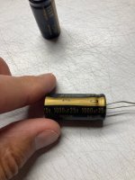
Hi. I've got a pair of 1000uF relatively low voltage Nichicon Muse capacitors with dents in them. I've had them for years at this point without knowing they were dented. They were part of a kit and not worth bothering the kit maker over, so. I'm trying to decide if they're usable in say the early stages of a low voltage power filtering circuit. With a cheap LC meter, they measure within spec, e.g. ~10% down of rating. There is this older thread discussing film caps with shipping damage and opinions seemed somewhat mixed.
So we have a bunch of speakers mostly not active that would probably fulfill the req's , but for most folks with low income there should be an option to build a DIY speaker that have no (serious) quirks!
I am referring here to this video : Login to view embedded media
$1000/pair for all parts except the cab - doable or not? (2WAY or 3WAY)
I'm building my first set of speakers. I have done months of research on drivers, designing crossovers, cabinet considerations, so let's please leave that aside.
I thought I would be clever and buy much cheaper parts than what I was planning on buying with equivalent specs to confirm the theoretical changes I was seeing in VituxCAD. I made three measurements using REW and my UMIK-1:
1) No crossover
2) Proposed first order crossover
3) First order crossover with a 1.5Ohm resistor in the woofer circuit intended to bring down a 100Hz peak.
Please ignore the shifts in SPL, I had the preamp at different levels on different days.
The resulting sweeps are telling me that the crossover I designed does not have an effect below 1k Hz.
This is the basic crossover circuit. As I understand the circuit, below is a description of how I wired it so my procedure can be checked:
The positive leg of the 6.8uF cap (treble), either post of the 270uH inductor (mid), and either post of the 4.7mH inductor meet with the positive wire of the amplifier at the same point.
Treble: The neg leg of the cap, the pos wire to the speaker, and either post of the 100uH inductor come together. The neg wire to the speaker and the other post to the inductor come together.
Mid: The other post of the 270uH inductor, the pos wire to the speaker, and the pos leg of the 10uF cap come together. The neg wire to the speaker and the neg leg of the cap come together.
Bass: The other post of the 4.7mH inductor, the pos wire to the speaker, and the pos leg of the 100uF cap come together. The neg wire to the speaker and the neg leg of the cap come together.
The three combined negative speaker wires and associated components are all bound together with the negative wire to the amplifier.
Can you identify any mistakes in my procedure that would cause the bass and mid circuits to come away unchanged? Subjectively, the sound is different at each of these three points, that is why the measurements under 1kHz all being the same surprised me.
X has suggested we run a thread for a useful circuit topology I have adapted from tube technology - the concertina phase splitter.
In tubes, we need two drivers for the AB/A output stage. These drivers must be in antiphase, since tubes are only 'n' type. We don't need this for a conventional pull push complementary output stage, since we have n and p types - ideal for a real world.
But there are situations in SS audio where power amplifiers require balanced drive. The first reason is the proaudio scene, where there are long lines all over a studio and usually strewn around with light cables, creating a hugely noisy environment. So balanced lines, if carefully configured, cancel this noise; this is a wonderful advantage and it relies on the two signals in antiphase. If both lines have the same noise induced into them, since the balanced requires antiphase signals the noise is common mode and is removed.
The simplest tube phase splitter is the single triode with equal loading in kathod and anode. Since current in the anode and kathod are identical, if these resistors are equal then the signal at the anode and the katod are also identical; just take the signal off through caps. This can be done with SS as well, and for even accuracy, you can use a complementary feedback pair.
I will post the schematic in within a couple of hours........ this can be used nicely with the Yarra to provide a balanced output.
Any issue or consideration when adding a film bypass cap in parallel to the electrolytic for AC coupling, with a wire connection to the film cap to the back of the board. So the bypass cap is remote and connected by low impedance cable as no room to fit a decent film cap direct with the electrolytic ?
Low activity on Tubes/Valves site this summer. As a teacher I have seven weeks off this summer... I have an EL36 Se project going on. One 6SL7 for one channel..
For all those who look desperately for the classic TDA1022 bucket-brigade delay lines, there are good news.
The well known German electronic-organ producer Dr Boehm used them decades ago and they still keep original NOS stock.
Today I received this e-mail:
Which means they offer them to a very fair price of 15,-€/each with 7% rebate at 10 pieces.
You may contact directly
Erik Jeromin <Jeromin@keyswerk.de>
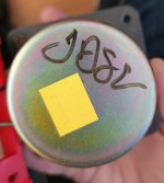
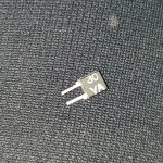
Hi.I have found this part. About 1000pcs. What is it? It measures About 100kOhm from 100Hz to 10kHz and 150kOhms at 100kHz. And Dc resistance about 390 ohms after long waiting on lcr meter. What is this part?
On the web are to find a lot of different upgrade versions.
But I miss a replace of the electrolytic caps after the rectifier (for anode voltage).
Who can recommend most important upgrade steps to get most enhancement in sound quality ?
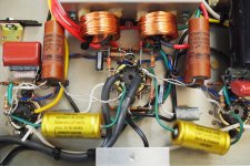
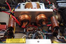
What is the aim of the air coil inductor in image 7-9 ?
Hi folks, one my beloved 434‘s just stopped passing audio. It appears to turn on okay, but I’m getting nothing from the output. Could anyone point me to where I might find a schematic of this model or perhaps one of its big brother, the 436?
Suppose you wanted to find a capable fellow forum member to collaborate on the design and build of something, like speakers or subwoofers. Ideally, during and/or after the final build stages and for listening sessions and hardware transport, the member wouldn't be located more than a state or so away; within driving distance.
Accordingly, added to the forum's Advanced search engine could be a field for finding US members by the state they reside in. Perhaps fields for similar uses could be also be added for those based in other nations.
In my boat I need a way to control line level to power amps volume, first to the subwoofers, but I will expand it to the two other power amps, to the front and rear speakers. The headunit sending out the line level signal is a Pioneer car audio headunit with nothing special, the subs are JBL marine 10" active, sealed subs and the two amps are Alpine and something I can't remember right now. But basically it works like any plain vanilla car audio stuff. The creator of CamillaDSP, @HenrikEnquist gave me the idea that I will go for, using stuff I know from before: A potmeter turned by an RC servo directly connected to it (I have a few ideas for that, it will be simple and totally reliable), controlled by an ESP32 (he actually said an Arduino, but I know ESPHome and didn't really need to learn Arduino, so I will use the servo library in ESPHome). The servo position will give me the position of the potmeter in degrees, which I can convert to a 0-10 or similar scale. That's not even the most important, the important is that I can hear that nothing is distorting.
So what kind of a potmeter should I use? I don't do advanced soldering, so I would prefer something either ready made or very easy. I found this on eBay:
It's an ALPS, seemingly legit, RK27 A100K, so 100 ohm. It also has a PCB where the connections are easy, I can solder that without problems. It's like replacing keys on my Matias Ergo Pro Keyboard. Would that one do what I need? Or do I need a different resistance, like 50 ohm? I see that it says 2x 50, so maybe 50 is per channel. I know close to nothing about this stuff (somewhere between Manuel and Basil Fawlty) and hope somebody can help me, and that I gave the necessary information.
Think I'm about ready to start my first DIY amp- entry level nothing major. Will do better when I get more experience and brains. Not sure how im powering protections boards yet or if i need them-
Anyway what do you think? Yes im on a budget still haven't found a case I want to use yet-
Any of you guys have some of the Panasonic erx 3 watt 0.39r resistors you could sale?
Also I need Panasonic erx 2 watt 0.24r resistors if you guys have some to sale?
Update 12. March 2023
The GB is closed and the VRDN boards are ordered.
Further status updates will follow in the thread as soon as there is news.
If anyone is interested in the boards, please PM me. When all attendees have their boards, I'll see if there are any left.
In consultation with bhjazz I start the GB for the VRDN boards for members in the EU. The GB will run until March 5th. Boards will be mailed to EU members upon completion of the GB and receipt of the boards.
As recommended by Mark the boards are made with 2oz copper plating and 4 layers. Finish will be ENIG, for color I will choose the cheapest (Blue, Black or Green, in that order).
Shipping up to at least 4 circuit boards within the EU costs € 3.70 uninsured, as registered mail with proof € 7.20.
From 500g (probably from 5 circuit boards) as registered mail with proof € 10.50.
In addition, I will offer cheap and fully insured parcel shipping in the EU.
I forgot about my compatriots. Shipping costs only for Germany: €1,60 unversichert als Brief, Hermes Shop to Shop €3,70, Hermes Paket €4,50.
Further information follows.
Please leave a message in the thread with the quantity you want and your location so I can add you to the list.
I can see that there is a low res on hifiengine, however I get this trying to log in;
"Registration blocked - your IP address is listed in at least one forum spam database"
Also VPN is not possible after their update.....
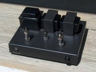
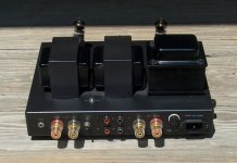
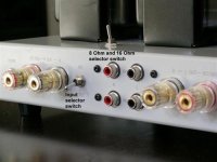
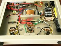
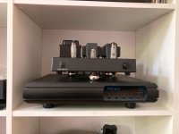
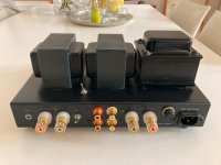
A fully assembled Tubelab Simple SE with separated and regulated PSU:
Universal PSU from DIY-HiFi Supply
Output transformers James Js--6123
Internal switch for Triode, Ultralinear and feedback mode.
Two taps on the transformer for different voltages
High quality Japanese film cap.
Svetlana KT88
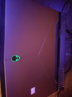
I've owned this Dell r17 m4 since about 2018. I got sporadic use due to reasons all moot. But probably three months in total.
It spent another five under a desk hence all the dust. That got on there before sealing it in a bag. I forgot it sounds good feeding sig to preamp allowing the stereo to take over.
My post intention why does it sound so good? I'm one bass junky and the bass from it is stand out in a high quality sense. Not for being booming loud and obnoxious at all. The rest is nice too, its balanced well.
The factory setting goes through the Alienware mixer, I could do without that. It made audio sound like its coming from a laptop.
If a totl S phone were ranked a 4 I would rank this a hard 7 1/2. I'm open ears to a 6 and beyond.
The real point whats the reason behind it? I'm not a pc wiz and I've tried finding out.
Hypothetically if one were to hot rod one of these to upgrade 2ch what would you change?
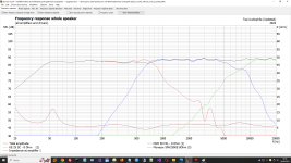
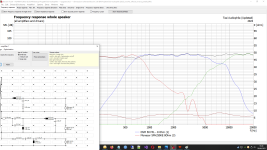
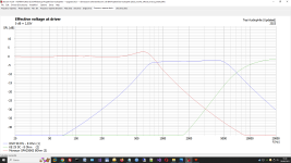
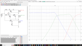
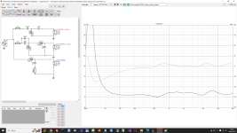
Unfortunately, at that time I was very inexperienced and had not used crossover design software, so by doing some simulations I realised that the frequency response is not flat.
For this reason I like to update my crossover without re-design from zero, just replace some inductors and capacitors and resistors.
Becouse most of my drivers are Visaton I have used BoxSim and after a lot of work I have found a good compromise with a budget of only 150 Euro of components.
The result seem good becouse the frequency response is flat.
After this I have tried to see what happen with VituixCad and unfortunately there are differences and the frequency response is not flat like BoxSim.
In particular there is an evident bump at 600/700 Hz.
At the moment I am stuck because I don't know who is right: BoxSim or VituixCad or simply there are other options that I don't have set.
Attached there are some screeshots that show what happen.
Do you think that I can trust of BoxSim ? or VituixCad is more accurate ?
I am trying to design my first tube amp.
And i am trying to make the bias for my end tubes (EL34 PP).
Since this is my first amp, i was thinking about making the bias adjustable.
I came up with the following:
The 10 ohm resistors are there to easily measure the current through the tube.
With the 1K potentiometer I can then play a bit with the bias setting.
And the 500 ohm potentiometer, I can use to make sure both tubes are tuned equally.
Right so first off - sorry, I don't mean to start clan wars with this question.
I've built a few kits, and for reading material I've bought LDC, the "Sound Reproduction..." third edition by Floyd E.Toole, and "Testing Loudspeakers" by D'Appolito... and read bits and pieces of them.
Also, I happen to have a DATS V3, and a Umik1 - I will perform all necessary measurements.
Usually when reading about crossover design it's all about passive / analog crossover design, and most questions I've asked regarding crossover design with DSP ended up in arguments between people discussing things that in my opinion were more related to analog crossovers - probably because that's what these people have been doing for the past few decades.. :-/
So to make a short story very long - I'll be using class D amplifiers to individually power my drivers and DSP to do the crossovers and PEQ when necessary.
Is there any reading material available on how to design crossovers when using DSP, instead of "learn how to do it in analog, including a lot of stuff you won't need when doing it using DSP, then convert that crossover to DSP" ?
I am in the process of building the power supply for a 6P15P-EV to 45/46 tube amp. The transformer I am using is huge and was originally in an organ amplifier. The organ was from the late 1950's, so I'm guessing the amp was designed to run at 110-115 Volts, while the voltage at my house is usually 120-125 Volts. The power transformer is grossly overspecified for my intended use, having powered dozens of tubes originally. It has two filament windings. One is 6.3 volts center tapped, and was used for two 6L6 power tubes, and the other is 12.6 volts center tapped, and was used to power the heaters of all the other tubes, so it is likely at least 5 amps. I am using Coleman filament regulators for the power tubes, and the 6.3 Volt winding for the heaters of the 6P15P-EV. This leaves me with an the unused 12.6 Volt center tapped winding. Can I use this extra 12.6 Volt winding to buck the transformer in order to lower the B+? While I am pretty sure that I can, I am not sure if there are there any downsides, so any advice would be appreciated. Additionally, I assume that the 12.5 volt secondary (or half of it for 6.3 Volts) would be used to buck the primary, but is there any way to use it to buck just the B+ winding? Typically, I need to use dropping resistors on the filament windings of these sorts of transformers to get them down to the proper voltage, so bucking the primary should not be an issue, but I would appreciate any input on the possibility of bucking just the secondary if there is a way to do it.
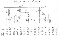
I've been attempting to reverse engineer the crossovers of vintage ADS speakers using the schematic attached. While calculating the quality factor, or "Q", of the second-order crossovers, I observed that the values were quite low in all crossovers, mostly below the defined range, such as in the Linkwitz-Riley (Q = 0.5) alignment.
For example, the woofer of the L730, with L = 3.50 mH, C = 33 uF, and Re = 3 Ohms, yields a Q of 0.291. Also true for the majority in the diagram.
I conjecture that the low Q was designed to provide increased impedance at the crossover region. Am I correct?
I'm trying to build a speaker enclosure using Fenlon 7 design (https://www.markaudio.com/wp-content/uploads/2021/08/Fenlon-70.png) where the panel width is 15mm.
The standard width of MDF that I can get where I live are 6 / 9 / 12 / 16 / 18 / 25 mm.
If I use 16mm panel instead of 15mm, what changes should I make?
FYI, I'm going to use Mark Audio Pluvia 7.2 HD driver with the enclosure.
Any advice would be greatly appreciated.
Thanks.
What do you cut yours with to make a clean edge for roller bits to ride smoothly along?
The only bit option I had has a 3mm roller. When I cut mdf with my jigsaw its hardly left with a smooth edge. By the time I clean it up by sanding its otherwise useless to me since my aim is laminating six 3/4" plys together to build up thickness.
I guess I could cut my pieces larger then sand them down to size, or sand after I laminate my pieces. That seems like alor more sanding than I signed on for lol. There has to be a better way.
I’m asking a lot of questions about smps and amplifier output output. I have this small unit that is rated at 36v/5a, are there any small things I can change to get maybe 7-8 amps out? The main reason I ask is I see nearly identical units that are rated at 7a. This question is partly looking for solutions to amplifier building and partly for overall knowledge about how these things work.
NOYITO AC to DC Power Supply Module 36V 5A 180W Max High Power Industrial Power Module AC 120V 100V-240V to DC 36V Power Suitable for Civil Industrial Electrical Power Supply (36V 5A) https://a.co/d/9SoArEn
My speakers recently stopped working and after looking at the board realized a part was burnt up, and quickly replaced it. They still don't work so I'm trying to identify the parts around the burnt up part and can't find any answers.
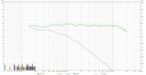
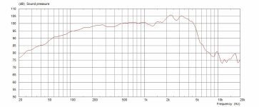
Hi, first post here. This is a celestion V30 speaker that is common in guitar speaker cabinets - an example of what the impulse response will be played through what I’m looking for explained below
This is going to be strange for most of you.
To put into simple terms, I’m looking for a set of speakers to take place of something like this
Those Laney speakers would do the job, but if I’m going to spend that money, I want the speakers to have use-age otherwise, too for audio work in general and listening. May as well be stereo. I will want these speakers to adapt to different needs like a “B” set of monitors for my studio
This is a trend in the guitar players world out there today. They call it FRFR: Full Range Flat Response.
Basically mic’d guitar speaker cabinet is turned into an impulse response, then played through “monitors” be that studio monitors, PA speakers, or these FRFR speakers, that are kind of a gimmick in my eye.
I will be using them to monitor guitar playing. Guitar speakers frequency response is as such (see picture of graph of Celestion V30 speaker)
Notice it drops off above 5K: the beaming issue is a bit different with electric guitar speakers 🙂
Whichever speakers I go with, they will have to be point source - either coaxial/dual concentric OR better to match a guitar speaker cab: single driver speaker. Needs to have good horizontal and vertical directivity.
Important: there can’t be any DSP unless the delay is under 1 ms
Speakers I’ve looked at so far
DMAX super cube 5: these would be great but the DSP is 7 ms latency
MOFI sourcepoint 10: these are probably the best option so far, as they have the physical aesthetic that is close to a guitar speaker, but they are too expensive also needing an amp.
GR-research LGK 2.1: these might work. Crossing over below 200 hz is acceptable. Getting 4 of these and making a wall of sound could be fun. Horrible horizontal directivity though
Aura-tones and other cube speakers would be a last resort
Geithain RL906 is an exception because it’s not a full range speaker, but it would perform like one and it would be useful for many tasks. They are active an have an amp… about the top of the budget
Hi,
im looking to take a burned active speaker (damadged amp) and create a passive speaker out of it.
the speaker is JBL 315 and it has 2ohm 14inch sub and a 8ohm tweeter.
considering I can make the right crossover to count for the different indepandance - will the result be a balanced sound ? meaning will the sub and tweeter volume be balanced or will the sub be much lauder since its indepandance is lower??
A friend got ahold of two NIB Goldwood 18 inch Woofers, model GW-18120. These seem to be PA or sound reinforcement woofers.
We wonder if they would be suitable for home hi-fi woofer (not subwoofer) use. It seems no reason why not. Plenty of older hi-fi speakers seem to have similar frequency ranges and sound pretty good. I'm not saying a smaller speaker like an 8, 6x9, or 10" shouldn't be considered in addition to this one for low midrange/high bass, though along with an 18" woofer size, the additional large-ish speaker deviates from the usual designs of the more vintage products. Then again, maybe they would be good mainly for an electric bass or organ amp or in a theater speaker cabinet. I really don't know. Trying to find a use for them.
I was wondering if anyone has ever trimmed away the tall tweeter flange on the Seas T18REX coax driver and what effects it had on the FR. I would think that tall flange around the dome would cause a few undesirable problems with ripple and diffraction. It otherwise is a decent driver but I can't help thinking it would hurt the HF performance in some way.
Picked up another car with a 2 post radio. Came with a Craig T701. It would light up, but all it would do is make occasional popping and crackle sounds on its own. Typical. Some time passed and I found a really nice Audiovox AVX-900. Hooked it up to power aaaaaand all it does is turn the cassette motor on with no tape in the slot. No lights, no display. That'll be a different post though.
I know neither of these radios are of great quality, but I would like to try and fix them before finding another pioneer super tuner.
With the Craig, my guess is either the Hitachi amp is bad, or its got bad caps in the amp section. Without a schematic, its going to be a crap shoot for diagnostics. Hopefully someone, or Perry, can point me in the right direction.
I know the right thing to do is to pull each cap and check them, but should I just go ahead and order the 8 caps in this area? I am assuming theyre all for the amp since they are right next to the unit.
If the caps are bad, is it possible to check the hitachi amp pack?
I'm looking to build my first class D amp for home hifi listening.
I intend on using 2x hypex UcD180HG amplifier modules. (46v)
I would like to use a linear power supply consisting of a Nuvotem Talema 230V ac, 48V ac Toroidal Transformer, 100VA 1 Output going into a Schottky Rectifier Filter Power Supply Board 120A DIY Sound Speakers 50V 10000UF, which will feed both amplifier modules
How far off am I guys? I know I have made errors which is why I would appreciate your knowledge and help.
I had 2 8GB and 1 4GB DRAM sticks in my pc.
The 4 GB was only single channel so I bought another off ebay.
Plugged it into pc and no boot.
So cursed ebay and the bad seller.
So had a look online for more memory.
I then decided to take a step back and try the new 4gb without the old one in and that booted.
So popped in old one again and after a while it booted too.
I had forgotten that if pc memory is changed the pc goes through a memory training routine and takes a lot longer to boot.
So unfairly cursed ebay and the seller.
Left some nice feedback on ebay.
Does anyone have any data regarding the exit angle on the B&C DCX50 compression driver? I can't find anything anywhere and looking at the driver throat doesn't show much. The fact its a coax driver makes things even more complicated.
JL makes a decent looking six. But I'd like to limit it at abouts $150 - 200$. If going that large it will require nibbling in to the storage portion in the console I'm making.
Dayton is relatively new to me, I took ownership of very little Dayton over time. But constantly am being impressed with the last Titanic 10", enough to buy more of them. They can compete respectfully with more expensive top JLs, really no reason not to apply a Dayton here.
Its for the rear section of this Chevy H-ell Camino console. Attached is a rudimentary plan page I drew up, or threw up hehe, while in stop and go traffic. Complete with coffee stain. A sealed section at the very rear indicated by the dotted line will house this small sub of some kind.
It only has to accentuate a 5 1/4" pair of coax in a car built for street n strip. Too much extra wait, not in the plans., nothing crazy expected, this approach would be wrong from go anyhow. Most important, simply filling bass in audibly with a bit of punch in to the adjacent seat maybe.
There are so many I'm in unfamiliar territory. BBB best bang for the buck is what I'm after @ $150.00 max if possible and if worth doing it.
I have a HiFonics Vulcan that wires in mono. A second 2ch will be required.
It would be extra neat to do a PR on the opposite side. Maybe or not. Creature comforts can start to add up quickly. The console will pop out quick and easily, hold downs are 6-8 ss wing nuts and threads. But still the lighter the better.
Please help me to choose a decent subwoofer for the very tight sealed enclosure.


 content removed
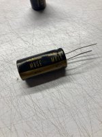


![20230602_023838[6537].jpg](/community/data/attachments/1087/1087659-d3bc3b0452592356b9cf6c9f728e05f2.jpg?hash=07w7BFJZI1)