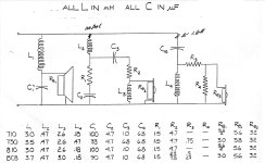
I've been attempting to reverse engineer the crossovers of vintage ADS speakers using the schematic attached. While calculating the quality factor, or "Q", of the second-order crossovers, I observed that the values were quite low in all crossovers, mostly below the defined range, such as in the Linkwitz-Riley (Q = 0.5) alignment.
For example, the woofer of the L730, with L = 3.50 mH, C = 33 uF, and Re = 3 Ohms, yields a Q of 0.291. Also true for the majority in the diagram.
I conjecture that the low Q was designed to provide increased impedance at the crossover region. Am I correct?
For example, the woofer of the L730, with L = 3.50 mH, C = 33 uF, and Re = 3 Ohms, yields a Q of 0.291. Also true for the majority in the diagram.
I conjecture that the low Q was designed to provide increased impedance at the crossover region. Am I correct?
Attachments
Last edited:
Not necessarily, it may have been compensating for a rise in response or something else. You'd need to take it in situ to find out.
But is there the potential for using this method of low-Q design as a stratagem to avoid low impedance at the crossover region?Not necessarily, it may have been compensating for a rise in response or something else. You'd need to take it in situ to find out.
Last edited:
Designing a proper crossover is always dependent upon the drivers used > their response & impedance.
The general starting point is using "Constant K" formular and then tweaking from there.
Constant K does not create impedance dips. 'M' derived component combinations start to impact impedance.
When you use L/C combinations that create impedance dips, you inherently create a peak in driver output.
Hence, we try to stay away from 'over reactive' L/C combinations.
In fact, unless you are trying to force an increased output of Fx in a driver, we do not use L/C combinations
that create that. Highly reactive L/C combinations not only create impedance implications, but also sonic.
Resistive attenuation techniques can also impact impedance, but that is a different subject.
(I still believe that you are using some kind of info. or software that is 'leading you astray')
IMHO, as can be seen in the schematic, the drivers utilized have a very low Re, i.e., woofers in a 2.8-3.0 Ohms range. This, I assume, is why they need to build the crossovers so that they cannot produce any lower impedances. And, if my hypothesis is accurate, then the low-Q design was one of the approaches they used.Yes there is, but why would they accept this compromise?
What you'll also see is an impedance peak at a standard cross. This is because of the typical use of -6dB, since that is one quarter the power for each.. so an impedance shortfall could be made up there. 2.8-3.0 ohms for Re is standard for four ohm drivers.
Is there Thiele Small parameters for these drivers?
Or manufacture data showing free air impedance curve
But yes, as mentioned the crossover points will likely be closer to
impedance rise. So actual Q be different.
Seems about right. Real world be closer to .5 or .7
makes more sense and much easier to grasp when working
with the actual driver impedance curve.
Specially now since its easy to observe behavior in a model.
Giving us a full list of all your drivers could be a great help.
Also, providing any specs. you have could also help.
Also, providing any specs. you have could also help.
You realise the target Q is the combined crossover and acoustic response of the driver? Taking the crossover by itself and saying Q is 0.291 yet I am expecting a LR 0.5... doesn't make sense
Looking further at your schematic diagram, it appears that you may be wanting to make a 6-8 ohm speaker system
using ~ 4 ohm drivers. This is not a practical endeavor and would require power loosing resistors.
If you are trying to use 4 ohm car audio drivers for home HiFi, you should use an amplifier that can drive 2 ohm loads.
With that kind of amp you won't need to worry much about crossover design, giving you 'free reign' of design options.
- Home
- Loudspeakers
- Multi-Way
- Can I do this to stay away from crossover's low impedances?
