crossoverless

Hi everyone .
I have read the web page below
https://www.caninialtoparlanti.it/nocrossover_.htm
it is written in Italian but if you use the translator you can understand it quite well.
I don't know if the metal basket has a function or if it only serves as a container for the glass wool.
I am interested in creating something else , a mechanical band - pass filter for a fairly limited portion of frequencies , for example , from 100 Hz to 300 Hz . what I would like to do however is not the complete elimination of the remaining frequencies but only a slight attenuation with respect to the frequency range that I want to pass.
in my case it would not be used to make a crossover but to modify the frequency response of the cabinet. could it work?
bye thank you

Windows based ASIO DSP for crossovers and EQ

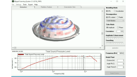
About 7 years ago I coded this exe that allows you to DSP speakers, subs, and rooms via ASIO.
(To this day it's still in beta.)

It's written in C# .Net 7 (.Net 4.8 originally.)
https://www.avsforum.com/threads/diying-a-dsp-processor-engine-solution.2626985/post-62400470

I called it "BassThatHz_ASIO_DSP_Processor" for lack of a better name.

Version 1.0.20 download link:
https://drive.google.com/file/d/1VHAYKhUI-yyDgx-Hx8wo1T9i_g7tIE7z/view?usp=share_link

Source Code download link:
https://drive.google.com/file/d/1fcDHaBRTaE4T9-ov3yo5Tpb4277lm87e/view?usp=share_link

Anyway, it has a number of features that I can "try" to briefly summarize here:

-The foundation of it is a highly tweaked and enhanced version of NAudio.
-Designed specifically for Motu AVB hardware interfaces (because that's all I own for testing/use.)

-Uses up to 64 threads (or more), had threading from the ground up (one thread per stream, unlimited streams, or at least 256 or whatever ASIO's limit is).
-Full 64bit floating point DSP, vanishingly low noise (something like -200db snr or whatnot).
-No added processing latency design (stays within the ASIO buffer at least.)
-FFT FIR (currently limited to FFT sized taps, of a power of 2, and uses overlap-save algorithm.)
-Biquad IIR with 0.01hz (or lower) to nyquist (only tested up to 192khz). Processing is a fraction of 1 ms typically.
-PEQ/HS/LS/LR, Hz/Q/Gain/Slope adjustments with advanced biquad overrides.
-Global Master Volume Input and Output; plus created each Stream has its own.
-Polarity flip and nearly unlimited delay.
-Mixer/Channel summation (input only), for those that need to mix inputs or create matrixed outs.
-Smart gain that reduces the gain to zero to avoid clipping when boosting (unlike dumb static gain).
-The limiter is a instant no-delay added brickwall type, which has it's own problems but exceeding the limiter is not one of them, the softness is, it clamps aggressively (instant brickwall within a given frame).
-All of the filters are zero added delay. except for FIR and the delay filter, obviously.
-Up to 256 channels in and another 256 channels out, 512 channels combined. (Motu is limited to 128 though, so I have no way to verify higher.)
-Each can have 100 or so filters each, there is no engine limit, but the stock windows GDI gui might have a pixel scroll limitation.
-A dedicated PC is not required, but strongly recommended for the best experience. It can run on a HTPC if necessary.
-Has a config save/load, optional startup delay, and an app shortcut can be set to auto-lunch on auto-logon. For those that want to make it an appliance. (Google auto-logon and auto-app start.)

-Currently uses .Net 7 but 8 will be out this November and that will be adopted pretty much right away, assuming it's better than 7, which it probably will be. (Faster etc.)

-Windows-based, which everyone already knows how to use / already has.
-No installer or setup msi or LSB is required for the exe. Only system requirement is .Net 7 Runtime for Windows Desktop. (and ASIO drivers with the devices fully powered on before opening the app.)

Typically uses <1% cpu and <100mb of ram.
Unlimited instances are supported.
Unrestricted use for personal-use/scientific or educational purposes. (There is no warranty and not to be used in a commercial setting, and none planned).
New versions are on a hobbyist best-efforts basis. (DSP is not my profession and I have no formal education on the topic, everything is done/learned the hard-way.)

The app is ugly and barebones, and that's intentional. Pretty pixels takes up precious CPU cycles and ram away from the DSP.
It's designed to run as fast as .Net core can (real-time DSP); and the only real bottleneck is the GC/managed-memory subsystem.

The only major things it doesn't have (yet) is DEQ, GEQ, auto-RoomEQ and auto-BEQ, and arbitrary length FIR.

GEQ I'm already working on, and DEQ I'd like to attempt in the upcoming builds... It will probably be my own variant of those as I don't like the historical parameters design constrains of conventional DSP implementations.

1680814873354.png


1680814933429.png

1680815009907.png


1680815173316.png


1680815287992.png


For some history/background as to "why":
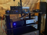
The reason I created it back in 2016 was because I have a large HT and didn't like the limitations existing HW based solution, such as Behringer DCX and miniDSP, I needed a lot of channels. I didn't want to link a bunch of them together nor pay 5 figure Trinnov amounts to get something comparable.
Prior I was using Adobe Audition but it was too slow, too buggy and eats up too much ram, and it's bloatware and subscription based.
I wanted something free, faster and more reliable, so I made my own. (i.e. You want it custom, you gotta Do It Yourself!)
1680815609389.png


1680815646252.png

1680816156924.png

1680815978168.png

A lot of channels.
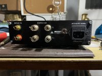
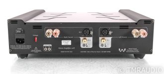
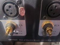
The Marantz is basically just an expensive licensed HDMI switch and DTSX/Atmos to analog XLR decoder for movie-mode.
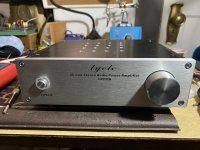
For serious 2ch music-mode I'm bitperfect ASIO to the Sabre Ref chips in the Motu's.
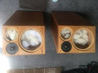
All speakers and subs are all fully active: 7.29.4 (Fronts are 4-ways, 108db/w/m, 2hz to 40khz +-3db, 14kW x 3. The ULF the subs are 4kW each, the PA subs are another 16kW.)
About ~100kW total burst potential, most of it bass.
1680816506778.png

That's just the front of the room (there's more...)
Anyhow: ridiculously amounts of power\loudness\overkill is my general-theme.
-I have over 23 years of experience with HT systems.
In 2016 I needed a DSP that could keep up with my addiction! Adobe\miniDSP\Behringer DCX just wasn't cutting it!
That and... I'm a just control freak... I wanted complete control of the DSP! (The rest is history.)

Anyway, maybe you find my Windows/ASIO-based DSP app useful for something too. Have fun!
-BTH out

For Sale Complete Elsinore Mk6 NRXC kit

SOLD

Been using the Elsinores for a couple of years now. Great design by Joe Rasmussen, but looking to do a new projects and don't have the space to keep them all.

For sale is a complete Elsinore Mk6 NRXC kit consisting of the following parts:

  • 8x SB17NRXC35-8
  • 2x D2608/913000
  • 2x Joe Rasmussen Elsinore Waveguides
  • 2x Bass reflex ports
  • 2x Crossovers:
    • 2x mundorf CFC16 0.47mH 0.23R
    • 2x Intertechnik aircore 3.9mH 0.67R
    • 2x Intertechnik aircore 2.0mH
    • 2x Intertechnik aircore 0.1mH 0.13R
    • 2x Intertechnik ironcore 22mH 4.26R
    • 6x Jantzen premium Elko 100uF
    • 2x Jantzen premium Elko 33uF
    • 2x Jantzen Silver Z-cap 1.8uF
    • 2x Jantzen Cross cap 0.47uF
    • 2x Mills MRA12 3R
    • 2x Mills MRA12 9.1R
    • 2x Mills MRA12 6.8R
    • 2x Path Audio Resistor 2.0R
Looking for 950 850 SOLD AUD (which roughly converts to: 570 USD / 520 EUR / 460 GBP) + shipping for the complete kit.

Attachments

  • PXL_20230326_053328176.jpg
    PXL_20230326_053328176.jpg
    433.9 KB · Views: 429
  • PXL_20230326_053412254.jpg
    PXL_20230326_053412254.jpg
    346.1 KB · Views: 417
  • PXL_20230326_053441769.jpg
    PXL_20230326_053441769.jpg
    423.3 KB · Views: 421

Tiny Speaker on a Gilmore JR?

I have a Gilmore Jr. 1/2-watt that I normally run through a home-made cab with a Celestion G10 Vintage.

I'd like to run the output through a DI box (Behringer GI100) into a console without going through the speaker. At the moment I can't really spend the money for an attenuator or dummy load, so I was thinking about using a de-coned speaker coil as a load.

I have a bunch of these 2", 8-ohm "full range" speakers, rated for 15 watts. To the best of my understanding, this should be fine (.5 < 15), but intuition suggests that it's a lot to ask of such a tiny device. The speaker is completely expendable, but I don't want to risk damaging the amp. Is this a reasonable thing to attempt?

High input LDO regulator

Hi,
I need some advice how to increase input voltage in LDO? Input voltage will be double +-50V. I need to build psu for preamp. So L7815CV; L7915CV max input 34V so it will fail.
I found circuit, I think its good idea, but I wanna use transistors BD139 & BD140 instead mosfets. Can someone help me and draw circuit? Resistor values etc. Zener I will choose 24V
Thank you!

Attachments

  • circuit.jpg
    circuit.jpg
    13.9 KB · Views: 153

Sony TA-5650 - To switch on or not to switch on?

That is the question.

I picked up a nice vintage amp in 1999 from a shop in Harrogate - 'cause we all knew the modern ones would stop working come the millennium 🙂

It's a tidy, clean TA-5650 (sn:601683), in OEM box and even has the wood side panels. I used it as my computer hifi through to about 2015 - never gave it a thought other than that it looked great, and sounded pretty good too.

It went into a cupboard in about '15 and it's now 2023 and I'm reading about suicide diodes and impossible to find JFETs and was going to plug it in but lost my nerve!

Given that it probably works fine, how can I be sure before I plug it in? Has it already been updated with new diodes, capacitors, etc. How can I tell? Can you all tell?

I've enclosed some photos in case there are some obvious tells, like the JFETs are a bit messy and HG-53 which looking around I'm wondering if it's a tell?

I really appreciate your experience, I can solder stuff and even own a hand-held oscilloscope but, I'm in a different pool here!

MPT

IMG_0609.jpegIMG_0611.jpegIMG_0610.jpegIMG_0612.jpegIMG_0613.jpegIMG_0614.jpegIMG_0615.jpegIMG_0616.jpeg

FYI: I can't register an account on HiFiEngine to get the manuals as I have the wrong everything.

300B line stage Mains transformer

Hello,

Planning to build 300B based low gain line stage based of Bartola Valves design. Limited experience before (only kit building), so trying to keep it safe first time - Will be using Bartola Gyrator and HT Supply PCB, and Coleman fillament regulators. Could somebody recommend a suitable high quality mains transformer and rectifier tube combination to get 250 B+ and 2x6,3V secondaries for the heaters? Help much Appreciated.

Attachments

  • 6F4C0389-4A97-4042-B236-A3F3657B742B.png
    6F4C0389-4A97-4042-B236-A3F3657B742B.png
    383 KB · Views: 349

Altec Vott Project - 811 horns and A7 Cabs

So I recently got back in to DIY audio after being out of it for years due to needing something to build. I ended up finding a set of 3x 811 horns and 2x A7 cabs for $400 which I thought was a pretty good deal considering I had to drive 3.5 hours to get them and they were in ok condition. Getting them home it turned out that only one horn worked, one needed a small repair and the last had no diaphragm (luckily the two working ones had the original diaphragm so that saved me a bunch of money getting things working).

Here is my current plan and issues I see at hand to get these suckers up and playing.

  1. They did not come with crossovers or drivers
    1. Solution for now - use my audison Bit one as an active crossover, eq, delay and preamp as it's just sitting here at my house
    2. I have a 2225h driver to put in the cabs which seem like they should fit
      1. Seems like the 808's and 2225h's would work with the passive crossovers out there (would the originals work as well?)
  2. They have been painted with duratex
    1. I have never had to remove duratex but I am going to try a heat gun first and then if that doesn't work I will try paint stripper
      1. Any tips on this?
  3. They will be refinished to look like furniture
    1. I am planning on trying my hand at veneering them in a light maple or pecan color so they look like furniture - there some examples online that are just amazing but I've never done this before so I will be happy as long as they look good
  4. I have some SEOS 10, DE500's as well as some smaller JBL horns with drivers I am going to play with that I already have, but following that I am selling everything else related off.
    1. Any thoughts on replacing the 811 with a waveguide for a home audio setup? Very few 1" drivers play as low as the 808-8's and I want to have the closest thing to a point source possible - long term I may one day upgrade to a JBL 2360 (or a waveguide that can play that low) and one of those new drivers that plays 300hz-20khz. However thats way down the road - mainly I want to be sure in this first incarnation, I get close to the original sound and then see how different horns/waveguides improve things (ancient technology vs. contemporary horn/waveguide design)

Precision Programmable Delayed Unmute & Instant Mute & Autoset to PS Nominal

I originally designed a Delayed unmute and instant mute at shutdown pcb with fixed parameters for my Nelson Pass Korg B1 – 24 volt input – which I programmed for a 4-second start delay, and mute either manually or when the power supply level dropped to 75% of nominal.

It worked well but I got to thinking about trying to build a similar circuit that could be user adjustable to better match the existing circuit and power supply and to enable individual preference.

I settled on the following parameters:

1. Self-calibrates to any supply voltage in the range of 10~30vdc.
2. Startup delay is user adjustable in the range of 1~60 seconds in 2 ranges, 1~10 & 11~60.
3. Instant shutdown is user adjustable in the range of 50~95 percent of nominal supply.
4. There is a manual mute switch.
5. Visual mute indication by blinking LED, either on-board or extended to front panel.
6. Relay is latching type, so powered both ways (not simple drop out), and switches in a very fast 4 milliseconds. No current flows -- thus no magnetic field across coil -- except momentarily during actual switching.

The circuit board is 2.5” x 1.5” (63mm x 38mm).

It draws 4mA continuously and the relay draws another 20mA momentarily during relay switching. The duration of the 20mA draw is the time it takes to charge/discharge 5V at the 120uF capacitor through a 250 ohm resistor (the relay coil), a calculated 3RC = 90ms with highest current limited to the first 30 milliseconds.

The user can manually set -- via two trim pots -- the startup delay (in seconds) and the power supply level where the relay mutes the circuit (as a percentage of power supply nominal).

The Startup Delay trimmer pot works in two ranges. The first half of rotation from minimum to midpoint sets a linear 1 – 10 seconds and the second half of rotation sets a linear 11 – 60 seconds. It can be set in two ways:

1. By trial and error – set an approximate rotation, check the delay by powering the circuit and timing the delay, making an adjustment and recycling the power again.

2. By voltages and simple math -- use 5.00V for value(1) and 2.50V for value(2) (OR you can measure the 5V supply to two decimal places for complete accuracy at the “5V” test pad near pin 1 of the DIP IC), do some simple math, and set the calculated voltage at the “TPD” pad using the Delay trim pot.

For 1~10 second delay:
calculate: value(1) / 20 * #seconds = voltage at pad TPD set by trim pot
Example for 6 seconds: 5.00 / 20 * 6 = 1.5V

For 11~60 second delay:
calculate: value(1) / 2 = value(2)
calculate: value(2) / 50 * (#seconds - 10) + value2 = voltage at pad TPD
Example for 15 seconds: 2.50 / 50 * 5 + 2.5 = 2.75

Mute on power drop to a percentage of nominal can also be set in the same two ways.

The percentage can be roughly adjusted by choosing an amount of pot rotation with minimum rotation giving relay activation at 50% of nominal, and maximum rotation 100% of nominal but software limited to 95% maximum or the muting level can be set by voltages and simple math:

Assume 5.00V or measure the 5V supply to two decimal places, note the value(1)
calculate: value(1) / 2 = value(2)
calculate: value(2) / 50 * (target% - 50) + value(2) = Volts at TP% set by percentage trimmer.
Example: mute at 80% nominal: 2.5 / 50 * 30 + 2.5 = 4.0

With a regulated power supply there seems to be no reason to set the percentage below 90~95% for a very quick muting of the circuit as power supply voltage drops. An unregulated supply could require a lower cutoff percentage.

Power supply voltage is checked many times each second to sense a drop, so muting with power loss is virtually instantaneous. Similarly, startup delay times are accurate to the second.

If there is interest, there would be no problem adding an output pad to another chip pin so that the board could be used as the basis for a circuit to delay connection and instantly disconnect speakers from a power amp. The manual mute circuit would instantly mute the output if an error signal was provided.

This board is very straightforward to assemble, start with the lowest height parts first and end with the 450uF capacitor. The relay does not lie flat on the board without help -- solder one pin first, verify the device is fairly level, then solder the other pins.

Programming the chip is perhaps something new to many, however this is the chip and program that is used in the UK to teach grammar- and middle-school students the art of programming and I found it to be quite straightforward plus there is a truly responsive group of experts at the forum who are more than happy to help anyone with any problem including the most basic programming questions. Don’t be afraid to try this program since all you’ll do is install the code to the chip (since the code is fully written), the programming software is free, and the only programming hardware you need is a PC and a $15 USB cable. Visit www.picaxe.com for info and see additional notes at the bottom of the BOM. The pcb cost me USD19 for five pieces from China, delivered in less than a week. The outfit is www.jlcpcb.com.

Attachments:

Photo (previous version, 20C, identical but without LED circuit)
PCB layout image 20D
Schematic 20D
Bill of Materials (BOM) 20D
Controller chip program (ZIP file) 20D
Gerber Files (ZIP file) 20D

Attachments

Streamer & DAC for B1

Good day!

As I am finally finalizing my B1 which I have started many years ago…

I’m looking to build a Streamer based on a raspberry pi and probably Moode which would work good with that little buffer.
On the other end are two active Newtronics Temperance.

I currently own a Hifiberry and I was looking at the DAC which is featured at the Moodeaudio site.
I was planning to add a display and make a nice wooden housing…

Would any of those work? Or would you recommend something else?

I’m looking for clean sound, no humm or any other weird noises besides the music.
I have also decided not to go down the CD transport route but instead rip all my CDs.

I’m looking forward to get into the audio tinkering again but I need a nice little system to get started…😊

Thank you

Small Coax Speaker

Hi, I just thought I'd post this design before I start cutting wood in case anyone can spot any problems.

Based on the the Seas L12RE/XFC coax, I don’t much like the look of the cabinet in the application note so I’ve re-worked the design. I’m happy to go through iterations so doesn’t matter much if I don’t get it right first time.

External dimensions are H 230, W 140, D180mm / H 9, W 5½ , D 7”. The cabinet is made of layered 25mm / 1” ply and the baffle is 12mm / ½” Richlite.

I’ve kept the baffle material thin mostly due to cost but have bracing from front to back. Also the screws to mount the driver go right through the speaker and fit threaded inserts on the back panel.

Volume is 2.3L / 0.08ft3 taking into account x-over components and driver magnet.

I’ve taken the port dimensions from the application note but made 2 ports of ½ area and sightly enlarged the flares.

Fusion 360 doesn’t have a ply material so pics show design in timber.

Attachments

  • Screenshot 2023-04-01 at 13.55.17.png
    Screenshot 2023-04-01 at 13.55.17.png
    758.6 KB · Views: 297
  • Small Coax 10 v12.png
    Small Coax 10 v12.png
    448.8 KB · Views: 259
  • Small Coax Inside.png
    Small Coax Inside.png
    417.5 KB · Views: 250
  • Like
Reactions: studiotech

TPA3255 Build Ebay special sounds great! Worth upgrade board?

Be easy on me Im relatively new to this DIY amp but do have experince with electronics and refurbing/fixing vintage amps etc as well as career in Electro Mechanical field. So I Finished this build using a 30 dollar ebay TPA3255 and it sounds excellent, just added an Alps 27 Potentiometer, for a power supply i have an external 48v 7amp used in Networking and telecommunications, its a low ripple low noise supply by ICT comm series. I have a dc jack mounted to back of case wich then runs to switch up front. I added a 4uf cap across the reset Mute which stopped the pop sound turning on and off per posts I saw here suggesting it.I have that seperate as It wouldnt fit in this case easily and this case has been chewed up inside over the last few projects. Ive since aquired better tools to do this stuff the right way going forward like better drill and bits as well as Dremel and few other doo dabs to aid in fabrication. The Alps pot shaft was quitelong so trimmed that down to fit the vol knob on (Yes I deburred and filed it beofre installing case. All and All Im quite pleased with this and am loving the latest Class D offerings, however Im wondering if Id actually see a sound improvement with one of these more expensive TPA BOARDS like the 3e and few others to justify the price? I also built a icepower amp using the 50asx and am waiting on wiring harness and am bulding one using the 125asx2 board so Ive been a class D busy boy lately. Pics of my system for attention. Any feedback always appreciated. TY guys Ive learned a lot lurking here.

Attachments

  • IMG_7631.JPG
    IMG_7631.JPG
    532.5 KB · Views: 252
  • IMG_7632.JPG
    IMG_7632.JPG
    391.5 KB · Views: 247
  • IMG_7633.JPG
    IMG_7633.JPG
    481.8 KB · Views: 263
  • IMG_7518 2.jpg
    IMG_7518 2.jpg
    422 KB · Views: 319
  • IMG_7687 2.JPG
    IMG_7687 2.JPG
    506.1 KB · Views: 336
  • IMG_7765.JPG
    IMG_7765.JPG
    484.1 KB · Views: 328
  • IMG_7766.JPG
    IMG_7766.JPG
    354.1 KB · Views: 272

Needing to replace RC4559 opamp used in motor drive circuit, Will any of these sub?

I’m fixing a Studer CD player I have. The disc motor does not spin and I believe IC7 is bad which is an RC4559, it looks like they’re only using one of the internal amplifiers.

IMG_6388.jpeg


I was looking through my stash and was curious if these would work in this circuit. Not sure if it’s less or more critical to match specs here than an audio circuit.

I have BA4560, JRC 4558 (the 4559 looks to be right between these two, just different manufacturers???), and then lastly TL072CP. I know the last one is a jfet design, but I’ve read it can be used as a replacement in some circumstances.

Any help with this would be greatly appreciated.

Dan

For Sale Dbx Driverack PA2 Dsp processor.

SOLD!!!

For sale my Dbx Driverack PA2 Dsp processor. I need 8 channels and digital inputs and that’s the why I’m selling.
Perfect condition. Awesome DSP.
Asking 420€ shipped within EU

Attachments

  • IMG_0613.jpeg
    IMG_0613.jpeg
    350.9 KB · Views: 110
  • IMG_0612.jpeg
    IMG_0612.jpeg
    333.4 KB · Views: 94
  • IMG_0611.jpeg
    IMG_0611.jpeg
    312.2 KB · Views: 111
  • IMG_0610.jpeg
    IMG_0610.jpeg
    497.6 KB · Views: 96
  • IMG_0609.jpeg
    IMG_0609.jpeg
    404.6 KB · Views: 92
  • IMG_0608.jpeg
    IMG_0608.jpeg
    470.1 KB · Views: 98
  • IMG_0607.jpeg
    IMG_0607.jpeg
    497.9 KB · Views: 87

UGS MUSES Scion Preamplifier

UGS-MUSE-Scion-Preamplifier-small.jpg

Scion derives from the Middle English sioun and Old French cion and is related to the Old English cīth and the Old High German kīdi (meaning "sprout" or "shoot"). When it first sprouted in English in the 14th century, scion meant "a shoot or twig." That sense withered in horticultural contexts, but the word branched out, adding the grafting-related meaning we know today.​
Welcome to the official construction and build thread of the UGS MUSES Scion Preamplifier. The reason I am starting this build thread is to share, have fun and receive feedback and input. Since its heavily based on the original UGS (Universal Gain Stage) MUSE edition preamplifier developed by Alex_TWN and Eric.D over at homecinema-fr.com all credits goes to them for making my version possible. I ended up at the original UGS-Muse Edition preamplifier as a result of stumbling over the Pass Laboratories XP-30 line preamplifier which use the NRJ MUSE volume IC (New Japan Radio Co.ltd MUSES72320) and a few clicks later, the UGS-Muse Edition Preamplifier was a fact. This preamplifier will make it possible to develop and build a state of the art preamplifier, but with custom solutions.

This custom preamplifier is heavily influenced by Lyngdorf Tact Millennium MkII Digital Amplifier which is no longer manufactured. What really made Millennium Amplifier different was the volume attenuator wheel. It had a very lush and firm feeling. Nothing obscured the rotation and it felt like it could spin for ever, there where no mechanical input and no play - it was rock solid. I first encountered this amp back in 1999 and I still remember to this day the feeling, in other words, I got obsessed with it.

The third inspiration is 1970's style LED displays - very old school, but I am in love with does types of displays. Therefore the display information will use the LED Matrix style found via Liteon LTP-305HR - the same led display can be found in Soulution from Switzerland.

- July 2023 -

I have contemplated my options and have decided that the synergy of my forthcoming audio system will benefit greatly from the incorporation of vacuum tubes (triodes) in the preamplification stage and hence using solid state is out of the question. I am moving over to Allan Wright's RTP3 (Real Time Preamplifier) with some modern modifications and convenience. One such convenience is going to be the use of a remote to attenuate the volume and I am moving away from resistive based to inductive based.

This thread was a good learning platform and I appreciate the contribution. In due time, I will post a link to the new thread and this time, it will not be guessing or back and forth. I will present the project as it is intended to become. Some prototyping will be necessary to iron out some potential issues, but other than that, it should be relatively straight forward.

>> Watch this space <<<

Oneminde​
  • Like
Reactions: angchuck

  • Locked
Blasphemy?

Most 'classic' speakers are judged on the their mid and high frequency performance together with cabinet construction. Rather than spending big bucks restoring these icons to their former glory why not take a moment, face facts? These speakers were the dogz back in the day but they are ill-equipped to play modern music. Why wouldn't you replace the original woofers, the ones where the surround has rotted and shredded with a small sub driver?
I have 40-year-old Marantz and Wharfedale cabinets where the bass driver's shot. They could be restored at ridiculous costs but maybe it was modern music that killed them in the first place.

Picked up an old Adcom GFT-1A with no FM

Picked up an old Adcom GFT-1A with no FM. The AM works great. I have looked around for a schematic but no luck. Has anyone had any experience with this model and problem..
The tuner scans fine and memory is also fine. I checked a few caps and so far they are all a bit over value (good). Any suggestions?
Best regards,
My 1st post here.
Soundtec

Nutube B1K PCB populated

Sell It with boutique components(i.e. Amtrans resistors and Panasonic caps) .Only the pcb populated Is on sale. Price 260 Eur shipped to Europe.
In case interested, i could sell it completed in chassis with dact attenuator,price on request

Attachments

  • IMG20230723112444.jpg
    IMG20230723112444.jpg
    449.1 KB · Views: 107
  • IMG20230723112433.jpg
    IMG20230723112433.jpg
    531.6 KB · Views: 114
  • IMG20230723112511.jpg
    IMG20230723112511.jpg
    403.4 KB · Views: 109

Help identifying RCA jacks?

Howdy. I bought this amp used about a year ago, and I'd like to sell it now. Unfortunately the individual I bought it from sent it to me without the caps? To the RCA jacks. He told me that's how they were made, I took his word for it. Just looked online today to confirm his claim before listing, and the amp is pictured with caps on the RCA jacks... So, I'm hoping someone can help me ID them so I can order replacements before listing the amp for sale. By the way, it's called the Wyred4Sound ST-500mkII. It uses ice power modules I believe

Attachments

  • 47459-7__59224.jpg
    47459-7__59224.jpg
    282.7 KB · Views: 95
  • 20230728_163504.jpg
    20230728_163504.jpg
    257.6 KB · Views: 100

Denon pre amp with Denon monoblocks

I have a two Denon POA 4400's and a Denon DCD 1420 pre amp. I am using the balance cables. All of a sudden today, my system went nuts. I am getting oscillating noise, even though it is still playing music. I am trying to figure out if it is the preamp our or something with the POA's. I have cycled power, and it is inconsistent whether it happens on both channels.................help.
Probably need to get new stuff...............got my mileage out these.

Modern equipment for AM/FM receiver adjustment

I've just picked up a LaFayette LR-5555 receiver for very little money with an eye toward using it for restoration practice before taking on my own Pioneer SX-series receiver (that I only just barely was able to get back from Crossed Paths Vintage in Texas after more than a year and almost no work done on it - DO NOT SEND ANYTHING TO THAT GUY!).

The area in which I am least equipped to restore a receiver like these is tuner alignment and from the Pioneer service manual I understand that I need these pieces of equipment:

  • FM signal generator
  • AM signal generator
  • AC voltmeter (I assume a garden-variety DMM will do)
  • Oscilloscope that can do XY (I have a Rigol DS1054Z)
  • Distortion meter
  • MPX signal generator
Now, back in the day each of those things would be a discrete piece of equipment. But given that I'd be walking into this with nothing but an oscilloscope and a DMM, in 2023 what is a solid way to complete the setup without traveling around the region to hamfests, taking chances on eBay, buying things off Amazon that are shipped from the far east of sketchy quality and/or difficult to use (I bought an audio function generator that's both), or just speccing out new HP-ish hardware that's hundreds a pop? Isn't there, like, software-defined-radio hardware that can do all this stuff? I'm not going to be making a living out of restoring receivers so paying top dollar for new do-it-all stuff or even top-drawer used pieces (like ~$500 on eBay for an HP 3325A) is something I can't see myself doing.

JAT501 simulated using TINA TI and possible improvements

Hi all,

I have been following John Audio Tech youtube channel for a while now and it has a lot of fun projects including this JAT501 amplifier. I have decided to put it together in a simulator to learn little more about amplifiers as a process. It has been fun to play with different inputs and examining what parts of circuit does what.

Another goal was to run Fourier series analysis in the sim to see what kind of distortion it might produce.

I really like the choice of output transistors - 2SC5200 and 2SA1943.
Was able to load those spice models from official website no problem.
Also using green LED model from Cordells website spice library.
All other components are default in TINA TI library.

Attached all files.

Attachments

  • sch.PNG
    sch.PNG
    27.1 KB · Views: 342
  • thd.PNG
    thd.PNG
    24 KB · Views: 299
  • jat501.zip
    jat501.zip
    117.1 KB · Views: 84

Suggestion for a chip amp to pair with PCM1798 in a toy music box

Hello, i'm a beginner in circuit design and audio circuit, but i want to make my first toy project.
I'm planing to make a simple board that will play sound from sdcard, and i chose pcm1798 to be the DAC chip. I don't know whether i can connect the output of that chip directly to a speaker and good with it, or i need an amp chip.

Calling all SCR experts

Hello all.

After retrieving my Dataman S4 which was last used about 6 months ago I found it dead. Hence I am in the process of reverse engineering the PCB.

The image is a snippet of my circuit and shows the first stage power supply. 15VAC comes in, gets rectified and then... meets a strange SCR based circuit.

SCR Circuit.jpg


What I know about SCRs one could write on the back of a postage stamp. At a WILD guess I think this some kind of elaborate regulator (at 8V?).

I wonder if there are any one here that can explain this circuit please. I wonder why the original designer plopped for such a whacky design instead of using a standard design.

Regards & thanks in advance, A

Material Testing: Carbon Fiber Skin on MDF and Plywood

I have been planning to build a speaker with a carbon fiber skin for awhile now, but every mention of using carbon fiber in a speaker cabinet is followed by doomsday type statements, with people saying that it's just really bad.

My gut response is to dismiss those comments, but I decided it is worth researching and testing before I commit to it. Carbon fiber is definitely not common, but I have found 2 examples of speakers using carbon fiber in the cabinets. One is a studio monitor with a carbon fiber skinned front baffle, and the other a high end speaker made from carbon fiber with aluminum honeycomb core.

The plan would be to apply a "skin" of carbon fiber over a cabinet after it is made. The questions I have are: Is it better to skin the outside only, or skin both inside and outside? What is the difference between skinning MDF vs Plywood? And how does a carbon skin compare to a hemp skin? Hemp is promoted as providing "damping" to a composite, and damping sounds good in the context of a speaker cabinet.

To test, I made a bunch of samples of all the combinations I am interested in. They ended up being 6"x 7". I put them in a test jig that "taps" them equally, and I measured the max SPL for a single drop. I took a bunch of measurements and averaged them.

The test jig is pretty simple. It has a board that lifts up against a fixed stop, and gravity swings it down. I set the test pieces on a thin foam strip to prevent rattling against the test jig. This made the results more consistent and repeatable.

20221015_135255_resized.jpg


Results:

Plywood, bare ACX 3/4": 108.93dB
Plywood with carbon on 1 side: 96.36dB
Plywood with carbon on 2 sides: 94.62dB
Plywood with hemp on 1 side: 105.61dB
Plywood with hemp on 2 sides: 98.5dB

MDF, bare, 3/4": 102.9dB
MDF with carbon on 1 side: 109.8dB (back side impregnated with epoxy b/c otherwise it will warp from moisture)
MDF with carbon on 2 sides: 102.88dB
MDF with hemp on 1 side: 108.86dB
MDF with hemp on 2 sides: 101.38dB

1" extruded polystyrene foam board bare: 110.4dB (taped down so it didn't bounce on jig)
1" extruded polystyrene foam board carbon 2 sides: 106.93dB

I also observed that the resonant frequency of the samples changes when adding the different skins, as one would expect. Tapping bare MDF makes a lower pitch than tapping bare plywood, but adding 1 layer of carbon to the MDF makes the resonant frequency roughly the same as the bare plywood. Adding the second layer increased the frequency again, but only the equivalent of a couple notes on a musical scale.

My takeaway at the moment is that nothing bad happens when you cover plywood or MDF with carbon fiber. The resonant frequency increases due to the panel becoming more rigid; the same thing happens if you put your bracing closer together. It also appears that common pine plywood is a good choice to use with a carbon skin. MDF seems to be more resonant with a skin, possibly because the resin soaks into the MDF and changes it's properties? And the foam didn't do particularly well in this test, which may be due to the fact it is so light weight that it bounces out of the test jig.

I may do more experiments. I was considering using carbon fiber with an endgrain balsa core material. That is denser than the extruded foam, but much less dense than plywood or MDF. It is rigid and light weight, and my guess is it is probably better than the foam.

How to plot frequency response of a filter?

Hi,

I am working on a graphic equalizer on PC and want to show graphically the final frequency response. Can somebody please tell me the below:-
1) Given the center frequency, Q and gain, how do I plot the frequency response, please show me simple formula if possible
2) Its a 1/3rd octave graphic equalizer, how do I choose the Q factor of each band?

Thanks and Regards,
Wonderfulaudio

Modelling MLTL Enclosures

Hello. I have a question about modelling MLTL enclosures. I am trying to make a MLTL style speaker using the Dayton Audio TCP115-4 (link)

I don't know how to use Hornresp or Akabak well enough to achieve this, so I have taken to just using WinISD to design a ported enclosure, then playing with the dimensions a little bit as instructed by Xrk971 in his Accidental MLTL thread.

My size constraints are that I want an enclosure no more than 30 inches tall, and 5 or 5.5 inches wide (external). What I arrived at is a 29 inch tall cabinet with 4" width and 4.125" depth (internal) with a 1.5" diameter port that is 4 inches in length.

Now, I am getting closer to the cabinet construction phase, and I am starting to wonder how much I am leaving on the table by omitting the use of this more involved simulation software.

I want my enclosure to be no more than 30 inches tall, which if I'm not mistaken means even with advanced simulation, I am starting to blur the line between MLTL and regular Helmholtz due to the limited quarter wave resonance accentuation at lower frequencies. So, given this, is it okay to take my more rudimentary approach towards cabinet design? Thank you!

Soldano hot mod v2 on oscilloscope

hello again .. I started this topic again because I have an oscilloscope. old for sure but it does its job very well .. so, I wanted to make an adapter called soldano hot mod. this adapter carries on it a valve tube called 6c10, very old with 3 triodes. so now how does this work,, i forgot to say that it is for a marshall jcm800 guitar amplifier. and we replaced the second valve tube of the amplifier with this adapter. what does it do? adds an extra amplification stage between the 2 triodes that the 12ax7 had .. and simply without pedals you have a natural pre amp stage with more gain (saturation) ...the problem is as follows, that the specific tube valve (6c10). it is quite expensive and very difficult to find, and that's why I decided to copy the design that is in the 6c10 but replace it with two 12ax7, i.e. the 3 triodes..in the end i made the design and tested it but it didn't work exactly as it should... now that i have an oscilloscope, i said to give it a chance to perfect it,,i simulated the marshall jcm800 preamp where the triodes were replaced with jfets j201 ... and it really works but sounds very similar .. when i also made the opator design and applied it to the simulation ... and i got exactly the same result as with the normal amplifier,and now the oscilloscope takes place, I should emphasize that the normal signal without the adapter is asymmetric and clipped .. after I applied the adapter the signal comes out as a clean square. and the amp sounds a lot of noise and buzz.. so I thought of a trick to approach the sine signal. I put in the output a 10K resistor in series and a 10n capacitor to the ground, and again a 10K resistor in series and a 10n capacitor to the ground and the same thing again... and somehow it made the signal better,there was a reduction in volume but it worked. more saturation and gain,,,I would just like to ask, how can the sign not come out? I send photos of designs and the oscilloscope. if anyone has any advice or help to "tame" the signal , I would appreciate it

Attachments

  • IMG_4541.jpeg
    IMG_4541.jpeg
    226.2 KB · Views: 209
  • IMG_4539.jpeg
    IMG_4539.jpeg
    331.2 KB · Views: 180
  • IMG_4538.jpeg
    IMG_4538.jpeg
    321.3 KB · Views: 216
  • HOTMOD SOLDANO - Copy.png
    HOTMOD SOLDANO - Copy.png
    22.8 KB · Views: 237
  • HOTMOD.jpeg
    HOTMOD.jpeg
    21.8 KB · Views: 309

Need help reducing THD in ECC88 Over/Under design

Hello again,

I am working on a version of the Over/Under design from TubeCAD to drive my current and future headphones. With the ECC99s as designed in the blog i got sub percet THD in LTSpice but after adapting it for the ECC88 i cant seem to get the THD bellow a few percent.

The goal is to drive headphones from 50 to 300 ohm, mainly 130ohm and up.

With the values in the LTSpice picture attached i am getting about 2.14% THD and mainly third and fifth order and id rather have the evens over the odds 🙂
1679325664917.png


The THD seems to decrease with higher loads as the amp goes more and more into class AB rather than A so i belive i should be looking at changing the bias of the tubes?

The input of 2.97V is the max output of the DAC that will be used. I am also looking to replace the MJE BJTs for some modern alternatives so suggestions on that front are welcome.

Attachments

  • 1679325639749.png
    1679325639749.png
    20.4 KB · Views: 353

Dome tweeter under near field scanner

Hello people,

I'm just confused to know how's ugly expensive dome tweeter reeact to signal.
I made a test of on of known model 1" textil dome tweeter (I can't show manufacturr name), by Klippel Near Fieeld Scanner NFS). Se the picture please.
Indeed all of domes move like this?!
I made a video about that., but Russian language, you can use subtitls if you interested in.
youtube

Attachments

  • Snapshot - 1.png
    Snapshot - 1.png
    214.7 KB · Views: 140

The importance of QMS in a cabinet with passive radiator?

Hi all -

Im after a bit of help. I found some Shahinian Arcs missing their bass drivers. They were cheap, the woofers Im guessing blew. The passive radiator is also missing.

Im working on a bit of a hit & miss approach. The tweeters are still working, the mids are blown (I will get to those) however in the meatnime I want to sort out the bass.

I've been recommended a pair of Scanspeak P21WO20 8" drivers for my purpose. One issue is cost & shipping. Given todays climate the cost is unjustifiably high to get these. I live in New Zealand.

I have found a pair of 830869 Peerless drivers to fit. I will need to mod the cutout a little bit to fit these. Im not after perfection, I have modded and fixed up several pairs of speakers before.

Anyway, the 830869 specs are almost identical to what I need (I have the T/S specs of the original woofers). That is, apart from QMS, which is about double of what I need, at 4.4.

The original woofer T/S specs were given to me by someone else who worked on what seems to be the same era of Arcs; the specs are (for one measured, ageing woofer): Fs = 24.2 Hz, Vas = 2.95 cu ft, Qts = 0.28, Qes = 0.32, Qms = 2.30, Mms = 29.9 gm, Re = 3.52 ohms, SPL = 87 dB, Le = 0.32 mH.

Im not sure of the overall cabinet size, however due to the design, the above woofer worked well in it. There is also a 10 inch passive radiator weighing approx 100gm in the original design. From what I have read on this, the QMS may not be the most importance factor in considering performance in this box (after all, its only one T/S factor). Many have said in discussions that it could also make for a livelier woofer with more engaging performance.

The data on the 830869 is here: https://www.wagneronline.com.au/pee...rivers/audio-speakers-pa/830869-7151/3245/pd/

Note that it has a bit of a peak at around 5Khz (but I presume the xover will roll it off before then. The 830869 has good Vas and Fs (I cant find many drivers at all matching these numbers). Of course, I will also need to address the different impedance vs shifting xover frequency issue.

Are there any views on this?

thanks in advance

Attachments

  • IMG_3588.jpg
    IMG_3588.jpg
    504.2 KB · Views: 123

Getting ChatGPT generated spice models to open in LT Spice.

So Chat GPT can spit out Spice models for anything you ask it.
Like I asked it to generate a circuit for Phono Preamp that uses two transistors and a 18 volt power rail.
It can also output .cir files.
But try as I might I cant get the files to open in Tinia TI, Protesu, Or LT Spice.
The hint seems to be in the first line which starts with the words Version 4.0
Do you know which spice simulator creates .cir or .asc files with version 4.0 in the header.

Here is the .cir file it created.
If you want the spice model files it created which I cant open I can share that too.
I think it would be a great asset if we could get AI to output the modells. We then open those in LT Spice and do the final tweaks and checks. You can also prompt the AI to output in a specific format. Like create a LT Spice XVII Model for xyz. And it will change its syntax.

Version 4
SHEET 1 880 680
WIRE -448 80 -704 80
WIRE -320 80 -448 80
WIRE -192 80 -320 80
WIRE -48 80 -192 80
WIRE -704 144 -704 80
WIRE -192 144 -192 80
WIRE -704 224 -704 144
WIRE -48 224 -48 80
WIRE -48 224 -704 224
WIRE -192 288 -192 224
WIRE -48 288 -48 224
WIRE -192 400 -192 368
WIRE -704 496 -704 400
WIRE -704 496 -736 496
WIRE -192 560 -192 480
WIRE -48 560 -48 528
WIRE -48 560 -192 560
WIRE -192 640 -192 592
FLAG -704 496 0
FLAG -704 144 0
FLAG -192 144 0
FLAG -192 80 0
FLAG -192 400 0
FLAG -48 80 0
FLAG -48 224 0
FLAG -48 288 0
FLAG -192 560 0
SYMBOL voltage -704 208 R0
WINDOW 3 24 56 Invisible 0
WINDOW 123 0 0 Left 0
WINDOW 39 0 0 Left 0
SYMATTR InstName VCC
SYMATTR Value 18V
SYMBOL cap -320 144 R0
SYMATTR InstName C1
SYMATTR Value 10nF
SYMBOL res -448 64 R90
WINDOW 0 0 56 VBottom 2
WINDOW 3 32 56 VTop 2
SYMATTR InstName R1
SYMATTR Value 47k
SYMBOL cap -192 256 R0
SYMATTR InstName C2
SYMATTR Value 330pF
SYMBOL res -320 256 R0
SYMATTR InstName R2
SYMATTR Value 47k
SYMBOL cap -192 416 R0
SYMATTR InstName C3
SYMATTR Value 330pF
SYMBOL res -320 416 R0
SYMATTR InstName R3
SYMATTR Value 47k
SYMBOL npn -48 192 R0
SYMATTR InstName Q1
SYMATTR Value NPN
SYMBOL npn -48 352 R0
SYMATTR InstName Q2
SYMATTR Value NPN
SYMBOL npn -48 512 R0
SYMATTR InstName Q3
SYMATTR Value NPN
SYMBOL res -48 288 R0
SYMATTR InstName R4
SYMATTR Value 1k
SYMBOL res -192 352 R0
SYMATTR InstName R5
SYMATTR Value 47k
SYMBOL res -192 512 R0
SYMATTR InstName R6
SYMATTR Value 47k
SYMBOL res -48 432 R0
SYMATTR InstName R7
SYMATTR Value 1k
SYMBOL cap -48 432 R0
SYMATTR InstName C4
SYMATTR Value 1uF
SYMBOL cap -48 592 R0
SYMATTR InstName C5
SYMATTR Value 1uF
SYMBOL cap -192 624 R0
SYMATTR InstName C6
SYMATTR Value 100uF
SYMBOL voltage -704 560 R0
WINDOW 3 24 56 Invisible 0
WINDOW 123 0 0 Left 0
WINDOW 39 0 0 Left 0
SYMATTR InstName Vin
SYMATTR Value AC 1V
TEXT -680 664 Left 2 !.ac dec 10 10 10k

Hifonics Brutus BRE2000.1D

Found this amp with a burned up trace under-side of one of the transformers at secondary ground. After repair, amp was able to power up and pass audio seemingly fine under small load so I re-mounted in the sync. I then tested at 2-ohm load, and after pulling about 10A of 13vDC current the sine-wave output turned into a saw and the amp went into protect. I can no longer get the amp to not protect, even with nothing connected. Its stuck in protect.

All FETs are measuring fine in circuit. The amp is back out of the sync and Im scratching my head a bit. Any thoughts?

Ferrograph Series 7

In this deck there is a high wattage resistor between the 2 drive motors - R105, 500 ohm. In the manual it states that this is now replaced by a choke - L102.
But, in the parts list, L102 is simply designated 180-000.

Does anyone know the L & R value of this ?

Obviously there was a problem with R105 getting hot, as it is mounted high up below the handle & if there is any dust on it there is a smell until it burns off.

Thanks.

Very Impressed with recent purchase!

I have owned several miniDSP products in the past and ordering, delivery and performance has always been great.
I just bought the Flex with Dirac Live and a Mic stand and couldn’t be happier!

The Flex is super easy to set up and get running. Dirac (now DL3) has been improved a lot. DL 3 is super intuitive and the instructions on screen to perform all the measurements is great. I will say that in order to really optimize your results you’ll need to dig down a few more layers in the onion to get all you can out of the Flex.

I also like how you can now switch between configs and the volume is reduced automatically for you and then gradually resumes the same volume eliminating the nasty click that occurred in previous models/versions.

When ordering the Umik 1 you get a small (4” high) tripod in the box but the deal of the century is for $15 get the Mic stand. It is fantastic and stands fully extended about 5’ tall. It is quite sturdy and very compact

All in all I am very impressed with the products miniDSP has produced over the years and they seem to just get better and better with time.
  • Like
Reactions: Henkjan and Davey

NuTube Headphone/preamp

Just got done today building a really cool headphone amp. It also has an output for line use, making it more versatile. I have built these before and have to admit it seems that the SP1 can make great music for headphones. So, look at the photos, as I have tried to point out certain aspects of this design. Many of you already know that Pete Millett designed this, so that says a bunch right there. I love the sound of DHT tubes. Oh and one thing that I especially like is the stacked mono volume controls. That is an idea that should have never died.

$300+shipping takes it. UNIT IS SOLD

Attachments

  • P7160001.JPG
    P7160001.JPG
    605.6 KB · Views: 164
  • P7180001_01.JPG
    P7180001_01.JPG
    300.9 KB · Views: 148
  • P7180003_01.JPG
    P7180003_01.JPG
    436.2 KB · Views: 157
  • P7180001.JPG
    P7180001.JPG
    355 KB · Views: 175

Icepower based Hifi power amp…

Hi everyone
I’m new here and found this forum in a search to get some help/ advise on potential parts to use in my new power amplifier.
I’ve begun by buying Icepower AS1200 boards and cable kits. Intend on running them as 4x600w on two channels (stereo).
I have the design clearly planned out and am very excited about it as I get to be a kid again and install VU meters.
However I have just one concern, use of a toroidal transformer. Forgive me but am not an electronic engineer so need some help. From what I’ve read the boards are plug and play. However I’m thinking I the long term, use of a toroidal transformer would be good to reduce interference. Would you suggest the use of one here. I’m looking at a 1500w - 2000w application as they are quite big enough, and I’m trying to get an idea of what size and if I should even use one in the first place. I’m just about to buy the chassis, so need to get all the dimensions for it before I do so. She’ll be a monstrosity of course, but will later couple with these 5- way bad boys I have in mind.
Anyway back to the question at hand. Would I need to use a toroidal transformer, would it make a difference, as I’m not using it to convert power, simply to nullify noise and interference. To be honest I want to builds very high end amp and as with everything it’s the small things that matter, to put it into context I even bought an anti static Matt to build this girl. I will post some pics of the plan/ design at a later point, after I finalise them case. Please could I get some advice on this?
Thanks in advance for your help.
Joel

Schematic for 845 amp with 211 driver

Hi everybody, this is my first tech thread.

I would like to build a 845 SET using as driver a 211 (with interstage transformer).

I know it's a difficult realization but I have all the time to study and improve the circuit.

Do you have a schematic I can use for inspiration?

I've seen some incredible realization of Thomas Mayer but I think his schematic is not publicly available.

Power Supply for SP10 MkII

Hi, I have just received a SP10mk II I won in a auction on the Japanese Jauce site. I knew it had no P/S when bidding. Overall the unit seems in good condition & spins very smoothly.

Now I need to make the P/S but am a bit of a nob with mains work.

Shown is the plug to arrangement for powering the unit, I do not need the 140DC voltage as this is just for the timing light. (we now have phones)

It seems quite straight forward to make up.

Question is can the main 32.5VDC feed be used (by changing up & down) vary the platter feed.

Cheers

Attachments

  • SP10 Power Supply Plug.png
    SP10 Power Supply Plug.png
    5.8 KB · Views: 105

For Sale ACP+ (assembled)

Selling my ACP+ to fund the next project.

I used AN Keisei (polar) on the power supply and Elna Silmic / Nicichons on the audio side. Resistors are all Dale or Vishay IIRC.

I assembled it without an on/off switch and chose flying leads rather than PCB-mount RCAs (I intended to put it in a case, but never got round to it).

Comes with the specified 230v / 24v SMPS. Will also include a bunch of spare Hexfets.

Item is in the UK - prefer a UK or EU sale.

Asking £199 including UK shipping - EU shipping extra.

5A1785B5-CD7A-4764-9321-1E05FC766791.jpeg

One pre-out to two power amps

I have an integrated amplifier that has a set of pre-out and main-in channels. I also have two power amplifiers.

Can I connect two power amplifiers to the pre-out channels of the integrated amplifier? I mean to use the integrated amplifier as a preamplifier and use Y-shape RCA interconnects to link the preamplifier to the two power amplifiers.

My concern is about the output impedance seen by the integrated amplifier (now used as a preamplifier), since it might decrease the total impedance presented to the preamplifier due to the parallel connection of the two power amplifiers.

Edit: Add an illustration.

Black line is floor-standing system and red line is bookshelf system.

Attachments

  • separated systems.png
    separated systems.png
    6.6 KB · Views: 129

Tru Technology C7.4T

Good Day folks,
Got this TT C7.4T in, has a burnt power supply and upon inspection all power supply caps are ruptured.
I've done a quick disassembly and some cleaning of the PCB and removal of the PS components (FETs, FET drivers and Caps).
the 494 was dead and this replaced, temporarily soldered in a MIC4427 and some IRFP1405 to get the PS up.

At first power up, I had high current draw. Poking around a bit I removed the 4 tubes from the pre amp circuit. Powered up again and the unit powered up ok with a fair stable current draw of 2.95A. This is where I've stopped, my tube knowledge is a bit limited.
I've contacted Tru, who indicated they don't work on equipment older than 10+ years.
Looking at the amplifier section. it seems to be a straightforward FET amplifier with JFET opamp front end.

Anyone go info/schematics on these tubes amplifiers?

Attachments

  • 1.jpg
    1.jpg
    734.3 KB · Views: 132
  • 2.jpg
    2.jpg
    660.8 KB · Views: 129
  • IMG_9016.jpg
    IMG_9016.jpg
    632.9 KB · Views: 131

Distortion at low volume disappears with changing the volume

Hello,

I have a Marshall Acton 1, I'm very fond of, but a while back I started to notice some distortion from what I think is the subwoofer. At first I noticed the distortion only occured on low volumes. With a little bit of searching, I found that the distortion only started after the music was playing for a while. I also noticed that when I opened up the volume and brought it back to the original more silent setting, the distortion was gone.

I have opened the speaker up but saw no damage to the woofer speaker itself. I fixated some wires so there was no way the woofer would be vibrating against them.

Now I think I start to notice that increasing the volume doesn't always work (anymore??.)

I have to say the speakers is often left with the power on....

I've searched the web for this issue but didn't find a thread describing the exact same problem. I did shower find that a capacitor could likely be a suspect...

I've placed the tread here because I found the amplifier would be a D-class one..

I am in fact a technical guy with a good understanding of electrics and a little knowledge on electronics, but I have no idea what to do to identify nor how to fix this problem.

I appreciate any form of help someone offers me. I throughly hope I can fix my beloved speaker.

Thanks for your time and any suggestions you might make,

Dieter

What is "good" impedance and phase?

As I'm designing my next speaker system, I'm taking into account more of the aspects of speaker design that I simply did not know (we build where we are, right?)... One of the things that my first system lacked was planning around impedance and phase. I tried to design the crossover with the knowledge I had, and this is the resulting phase and impedance (according to XSim).

1690486363441.png


One of the things pointed out to me was that the impedance of ~2.3 was lower than optimal load for amps. Nothing was said about the phase, but I know it is directly related to impedance just from seeing them both move if I put an L-Pad in place, for example.

So I hunted down a graph of one of the Perlisten s7t so I could have a model of a truly high-end speaker to learn from (rights and gratitude to stereophile: https://www.stereophile.com/content/perlisten-s7t-loudspeaker-measurements
https://www.stereophile.com/images/1121Perl7fig1.jpg ) I see the impedance dips to 3 ohms, are dips better than a constant low load? A constant load is better for the amp, right? This impedance varies quite a bit (relatively to mine, anyway)... but I guess that isn't bad? A constant low load is worse than a varying load? How much load variance is acceptable/optimal?
1690487286741.png


And then phase... Trying to stay close to 0 is easier for the amp, right? But how much variance there should be allowed/optimal?


On my new design, I can get either of the following (because speakers are really all about compromise, aren't they):
This fairly flat impedance and phase, at a slightly lower SPL and frequency response range:
1690488051809.png


Or this "worse" (?) impedance and phase, but with a slightly higher SPL and better frequency response range:
1690488158558.png


If both are acceptable, I'd like to go with the second option since it has better SPL and FRD.... Thoughts? I've done some digging but can't find a general rule of thumb for what makes an "optimal" system with these particular questions. Are there articles about this already that I missed?

Thanks, all!
Jess

ESL measurements

Getting ready to part with my ESL speakers. Others might be curious about the performance of my panels made around 1977 from Dayton-Wright cells.

These are FR (1/6 smoothing) and distortion (dB below fundamental). No EQ. Mic at listener's position, 10-12 feet. Rather small room with reflections. Middle loudness. Path includes all kinds of vintage boxes and DSP (set flat). Lots of noise around my house when measurements were taken so some false peaks are present. "-60dB" is 1% distortion, which is not bad for this kind of measurement with speakers.

Attachments

  • Speaker no cloth.jpeg
    Speaker no cloth.jpeg
    169.7 KB · Views: 157
  • L and R panels FR full range with no EQ.jpg
    L and R panels FR full range with no EQ.jpg
    62.2 KB · Views: 155
  • L and R panels distortion full range with no EQ.jpg
    L and R panels distortion full range with no EQ.jpg
    68.9 KB · Views: 156
  • Like
Reactions: geraldfryjr

Asymmetric Baxandall Tone Control Circuit

Dear fellow audio nerds,

I have a question regarding a modification of the baxandall tone control.
We all know the ususal circuits of symmetric cut/boost with +/- 12 or 15 dB.

In DJ mixers you sometimes find -22 dB cut and +6 dB boost.

I am looking for a circuit with such asymmetric cut/boost values, preferably a 3-band design.
I already tried to simulate different circuit variations, but with no luck yet.
Are logarithmic pots used instead of linears? Any clues are helpful.

Thank you and best wishes,
Dennis

Designing an output transformer using a power toroidal transformer

Hello.
I tried to purchase a commercially available product as an output transformer to operate a full-range ESL, but I was hesitant because it was expensive.
Please tell me how to design an output transformer that uses a toroidal transformer for power supply and what precautions should be taken.
It may be easy for those who are familiar with electricity. I felt it was difficult to trade off in various aspects.

That's my understanding for now.
As a basic usage, the primary and secondary are reversed from the original usage of the power supply toroidal transformer.
When using a 50VA 230V/6Vx2 transformer for each of the front and rear stators, the calculation is about 1:76.
That's about it.

Are there any common transformer combinations that you can say, "I can't go wrong with this set"?
What are the transformer specifications, usable capacitance, and maximum input?
For full range:
For treble:
For base:

By using 4 or 6 transformers, using the LV side in parallel and the HV side in series, you can boost the voltage even higher. Does the number of transformers increase the corresponding capacitance?

Is the approximate corresponding capacitance determined from the combination of transformers used?

What is the allowable turns ratio? Up to 1:120? What kind of problems will occur if it is exceeded?
Can you calculate the frequency to roll off? Are there any problems with low frequencies?

Can a transformer whose dielectric strength is unknown be used as an output transformer? Are there required safety standards?

It is not the case that the higher the rated power, the better. Is there a standard for selecting the rated power of the transformer?

6SL7 National Union The best out there

Matched Nos pair of the best 6SL7 tubes out there in top condition, the same year of production withblack glass and black anode. Price would be 100 eu including tracked and insured shipping in the EU! . Or make me some offer becose I dont use this and I dont need this. Payment paypal for friends.

Attachments

  • IMG_20230406_114108.jpg
    IMG_20230406_114108.jpg
    373.7 KB · Views: 242
  • IMG_20230406_114133.jpg
    IMG_20230406_114133.jpg
    332.1 KB · Views: 199
  • IMG_20230406_114245.jpg
    IMG_20230406_114245.jpg
    198.5 KB · Views: 209

For Sale Pair of monster Renkus Heinz SSD 5600 (5.6” diaphragm, 2.4” exit) 8 ohm midrange compression drivers

Spec sheet here: https://forums.melaudia.net/attachment.php?aid=6183

They’re heavy beasts at 14 kgs each and are rated to 200 W at 250 Hz (!) so would be ideal for crazy large horns (e.g. W.E/SATO).

Some discussion here: https://www.diyaudio.com/community/threads/r-h-ssd-5600.289122/ and https://audioabattoir.com/t/the-man-cave/4171

Both measure 5.3 ohms and play fine when swept from 200 Hz upwards. No buzzes/scrapes etc.

In excellent condition, except that one driver is missing its label and this one has some hairline cracks and some missing paint on one side (see pics). Purely cosmetic.

I’m based in Dublin and cash-on-collection most welcome, but happy to ship (preferably UK/EU) at buyer’s expense and risk.

Asking €700 and payment via bank transfer or paypal friends/gift.

I have another pair although only one with a working diaper but happy to do a deal with the buyer if they want a spare motor/diaper (as they are now quite hard to find).

PM for further pics/details etc.

Cheers
Adrian

ltspice fft shows wiggles

I am adapting a jfet buffer to suit my configuration. Please review the attached ltspice artifacts.
I am seeing some oscillations(?) after 100K Hz in the FFT output. What is it indicative of? The wiggles almost disappear if I connect the RC filter at the output (R11, C4), but I'm not sure if its required.

Attachments

  • jfet-buffer-fft.png
    jfet-buffer-fft.png
    10.2 KB · Views: 119
  • jfet-buffer.png
    jfet-buffer.png
    31.1 KB · Views: 129

Jamo Concert VII crossover help

Hello

I've gotten myself a pair of jamo concert vii speakers.

The previous owner took the crossovers out, and I cant seem to find the correct way to connect them back (i did replace the old capacitors)

On The crossover I've tried the following
Woofers connected to w- and w+
Tweeters to t- and t+
Midrange to sq- and sq+ together with the input from my amplifier

I can sort of get it to work, but the sound isn't right. What am i doing wrong?
Projects by fanatics, for fanatics
Get answers and advice for everyone wanting to learn the art of audio.
Join the Community
507,685
Members
7,884,242
Messages

Filter

Forum Statistics

Threads
406,036
Messages
7,884,242
Members
507,685
Latest member
EvenLouder