I originally designed a Delayed unmute and instant mute at shutdown pcb with fixed parameters for my Nelson Pass Korg B1 – 24 volt input – which I programmed for a 4-second start delay, and mute either manually or when the power supply level dropped to 75% of nominal.
It worked well but I got to thinking about trying to build a similar circuit that could be user adjustable to better match the existing circuit and power supply and to enable individual preference.
I settled on the following parameters:
1. Self-calibrates to any supply voltage in the range of 10~30vdc.
2. Startup delay is user adjustable in the range of 1~60 seconds in 2 ranges, 1~10 & 11~60.
3. Instant shutdown is user adjustable in the range of 50~95 percent of nominal supply.
4. There is a manual mute switch.
5. Visual mute indication by blinking LED, either on-board or extended to front panel.
6. Relay is latching type, so powered both ways (not simple drop out), and switches in a very fast 4 milliseconds. No current flows -- thus no magnetic field across coil -- except momentarily during actual switching.
The circuit board is 2.5” x 1.5” (63mm x 38mm).
It draws 4mA continuously and the relay draws another 20mA momentarily during relay switching. The duration of the 20mA draw is the time it takes to charge/discharge 5V at the 120uF capacitor through a 250 ohm resistor (the relay coil), a calculated 3RC = 90ms with highest current limited to the first 30 milliseconds.
The user can manually set -- via two trim pots -- the startup delay (in seconds) and the power supply level where the relay mutes the circuit (as a percentage of power supply nominal).
The Startup Delay trimmer pot works in two ranges. The first half of rotation from minimum to midpoint sets a linear 1 – 10 seconds and the second half of rotation sets a linear 11 – 60 seconds. It can be set in two ways:
1. By trial and error – set an approximate rotation, check the delay by powering the circuit and timing the delay, making an adjustment and recycling the power again.
2. By voltages and simple math -- use 5.00V for value(1) and 2.50V for value(2) (OR you can measure the 5V supply to two decimal places for complete accuracy at the “5V” test pad near pin 1 of the DIP IC), do some simple math, and set the calculated voltage at the “TPD” pad using the Delay trim pot.
For 1~10 second delay:
calculate: value(1) / 20 * #seconds = voltage at pad TPD set by trim pot
Example for 6 seconds: 5.00 / 20 * 6 = 1.5V
For 11~60 second delay:
calculate: value(1) / 2 = value(2)
calculate: value(2) / 50 * (#seconds - 10) + value2 = voltage at pad TPD
Example for 15 seconds: 2.50 / 50 * 5 + 2.5 = 2.75
Mute on power drop to a percentage of nominal can also be set in the same two ways.
The percentage can be roughly adjusted by choosing an amount of pot rotation with minimum rotation giving relay activation at 50% of nominal, and maximum rotation 100% of nominal but software limited to 95% maximum or the muting level can be set by voltages and simple math:
Assume 5.00V or measure the 5V supply to two decimal places, note the value(1)
calculate: value(1) / 2 = value(2)
calculate: value(2) / 50 * (target% - 50) + value(2) = Volts at TP% set by percentage trimmer.
Example: mute at 80% nominal: 2.5 / 50 * 30 + 2.5 = 4.0
With a regulated power supply there seems to be no reason to set the percentage below 90~95% for a very quick muting of the circuit as power supply voltage drops. An unregulated supply could require a lower cutoff percentage.
Power supply voltage is checked many times each second to sense a drop, so muting with power loss is virtually instantaneous. Similarly, startup delay times are accurate to the second.
If there is interest, there would be no problem adding an output pad to another chip pin so that the board could be used as the basis for a circuit to delay connection and instantly disconnect speakers from a power amp. The manual mute circuit would instantly mute the output if an error signal was provided.
This board is very straightforward to assemble, start with the lowest height parts first and end with the 450uF capacitor. The relay does not lie flat on the board without help -- solder one pin first, verify the device is fairly level, then solder the other pins.
Programming the chip is perhaps something new to many, however this is the chip and program that is used in the UK to teach grammar- and middle-school students the art of programming and I found it to be quite straightforward plus there is a truly responsive group of experts at the forum who are more than happy to help anyone with any problem including the most basic programming questions. Don’t be afraid to try this program since all you’ll do is install the code to the chip (since the code is fully written), the programming software is free, and the only programming hardware you need is a PC and a $15 USB cable. Visit www.picaxe.com for info and see additional notes at the bottom of the BOM. The pcb cost me USD19 for five pieces from China, delivered in less than a week. The outfit is www.jlcpcb.com.
Attachments:
Photo (previous version, 20C, identical but without LED circuit)
PCB layout image 20D
Schematic 20D
Bill of Materials (BOM) 20D
Controller chip program (ZIP file) 20D
Gerber Files (ZIP file) 20D
Attachments
-
BOM Mute and Delay 20D 14M2.pdf262 KB · Views: 90
-
Delay and Mute 20D 14M2 GERBER.zip10.3 KB · Views: 84
-
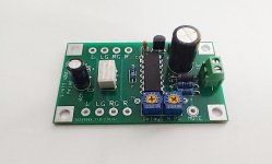 Photo Mute & Delay 20C .jpg141.9 KB · Views: 141
 -
Schematic Mute and Delay 20D 14M2.pdf32.3 KB · Views: 1,272
-
Mute and Delay 20D 14M2 NO_SERTXD.zip2.3 KB · Views: 73
-
 PCB Image Mute and Delay 20D w LED.jpg322.5 KB · Views: 121
Last edited:
