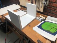
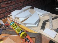
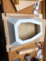
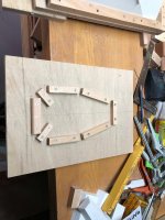
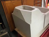
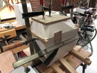
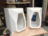
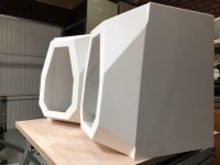
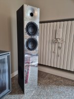
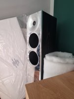
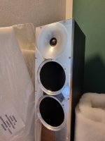
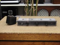
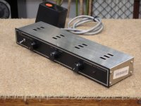
If anyone needs an artisan-quality loudspeaker-cabinet builder...

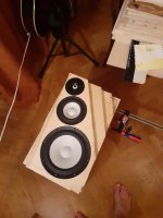
Roxy Deluxe 400ph.jpg


J Marks Eton Fountek Build 400ph.JPG


The custom furniture designer and builder I have been using for the past few years for my loudspeaker cabinets usually does large projects such as beds, dining-room tables, and other such furniture; please see examples at the link.

https://www.custommade.com/by/corwin-butterworth-custom-furniture/

He does very elegant work--he studied at the famous Rhode Island School of Design.

Corwin is looking for some smaller fill-in jobs, so I thought I would pass along his contact information (Corwin Butterworth: corwinb74@icloud.com), and show a couple of the cabinets he made for me.

Admittedly, each of these designs has its over-the-top aspects.

The front panel of the 2-way with the gold-plated tweeter (circa 7 Liters) is Richlite Bamboo Statum composite 1-inch thick ($72 per square foot plus shipping); the perimeter edge had seven coats of traditional hand-rubbed violin varnish applied by an award-winning violin maker. The coloring agent for the violin varnish was powdered gemstone amber in poppyseed oil; circa $95 the teaspoon. So, that's an over $1,000 pair of small cabinets.

The other cabinet (circa 10 Liters) has an mdf shell, but the corner-edge protectors are of Extreme Tiger Flame Maple intended for high-end guitar and uke work (don't ask how much that costs per board foot), and the front panel is a Baltic Birch/Richlite clad composite. Probably circa $700/pr.

Corwin is very easy to work with. Shipping is of course an issue, and careful packing is a cost to keep in mind. So, probably the ideal customer is in the upper right quadrant of the Lower 48 US states, who is building a smaller 2-way or 3-way. Probably not somebody in Arizona who need a massive Transmission Line build.

Highly recommended.

john
  • Thank You
Reactions: GM

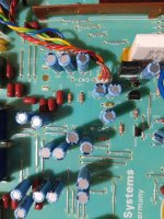
Upgrade oscillators in a Chinese - (not original) Amanero board

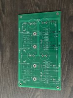
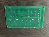
Hello . I bought a Chinese board that resembles the original Amanero. I would like to put better oscillators for the sound. Can you help me with advice? What exactly would fit in the place of what is there? I have attached links to pictures of the plate below.

https://ibb.co/9TQ1wHM
https://ibb.co/zNMdBQ3
https://ibb.co/0DNL6wr
https://ibb.co/X44xRt2

LaVoce FBASS08-18 Alternative?

Hey everyone,

I'm hoping to build a pair of these speakers but I'm having a hard time locating all the parts in the US, or from places that will ship to the US. Does anyone have an alternative to the LaVoce FBASS08-18 that might be easier to find?

I'm also not set in this specific build, so if anyone might have a suggestion for a similar build with easier to source parts, that would be great as well.

Thanks!

ChatGPT designed full range speakers

Here is my quick chat with GPT to see if it can help design boxes based on its LLM training...What do you think? It Likes to make stuff up so hard to know how accurate the rest of the information is.

@planet10 @Scottmoose @chrisb


User
Can you output the optimum box dimensions for a specific speaker driver if I give you the specs?


As an AI language model, I can certainly help you with the calculations required to determine the optimum box dimensions for a specific speaker driver, provided that you give me the necessary specifications. However, please note that the final determination of the optimum box dimensions may depend on various factors such as the desired frequency response, the intended use of the speaker, and other design considerations.
To begin with, please provide me with the following specifications of your speaker driver:
  1. The driver's Thiele-Small parameters, which typically include:
  • Resonant frequency (Fs)
  • Total Q factor (Qts)
  • Electrical Q factor (Qes)
  • Mechanical Q factor (Qms)
  • Equivalent air volume of compliance (Vas)
  • DC resistance (Re)
  • Voice coil inductance (Le)
  1. The driver's rated power handling capacity and nominal impedance.
With these specifications, I can use mathematical models and formulas to calculate the optimal enclosure volume, port size, and tuning frequency that will result in the best performance from your specific speaker driver.

User


Here you go. Parameters FS 97.4826 Hz VAS 1.1523 Ltr RE 6.8 Ohm QMS 3.7689 QES 0.7752 QTS 0.6429 Bxl 3,1071 Txm SPL 83.41 SD 0.0023 m² CMS 1.5733 mm/N MMS 1.6942g RMS 0.2753 WM RAT 307716 WA RMT 1.6140 WM MMD 1.6322g h0 0.13% L1kHz 1.0575 mH PWR 7 Watts (Nom) X MAX (Mech) +/- 3.5mm (One way)


Thank you for providing me with the Thiele-Small parameters of your speaker driver. Based on the specifications you have provided, I can help you calculate the optimal enclosure volume and port dimensions for your speaker.
Using the Thiele-Small parameters you provided, we can calculate the following parameters required for enclosure design:
  • Free-air resonant frequency (f0): 97.4826 Hz
  • Equivalent volume of air compliance (Vas): 1.1523 Ltr
  • Total Q factor (Qts): 0.6429
  • Effective radiating area (Sd): 0.0023 m²
  • DC resistance (Re): 6.8 Ohm
  • Voice coil inductance (Le): 1.0575 mH
  • Mechanical resistance of the driver (Rms): 0.2753 kg/s
  • Mass of the diaphragm (Mms): 1.6942 g
  • BL product (Bxl): 3.1071 Txm
To determine the optimal enclosure volume and port dimensions for this speaker driver, we can use the Thiele-Small parameters to calculate the parameters for a sealed and a ported enclosure. Here are the recommended enclosure dimensions for a sealed enclosure and a ported enclosure:
Sealed enclosure:
  • Optimum enclosure volume (Vb): 9.99 liters
  • Optimum Qtc: 0.707
  • Optimum box dimensions: 38.56 cm (Height) x 22.56 cm (Width) x 18.62 cm (Depth)
Ported enclosure:
  • Optimum enclosure volume (Vb): 18.13 liters
  • Optimum port length: 9.46 cm
  • Optimum port diameter: 5.08 cm
  • Optimum tuning frequency (Fb): 43.82 Hz
  • Optimum box dimensions: 45.72 cm (Height) x 27.94 cm (Width) x 25.4 cm (Depth)
Please note that the dimensions listed here are only recommendations based on the specifications you provided, and there may be other factors to consider when designing an enclosure, such as the desired frequency response and the intended use of the speaker. It is recommended that you consult with a speaker enclosure designer or use specialized software for further optimization of the enclosure design.

User


What response curve would this give?

Based on the recommended enclosure dimensions for the sealed and ported enclosures that I provided earlier, we can estimate the frequency response of the speaker driver using a modeling software or simulation tool.
For the sealed enclosure, the recommended optimum enclosure volume of 9.99 liters and an optimum Qtc of 0.707 would result in a relatively flat frequency response with a -3 dB cutoff frequency of approximately 61 Hz. This would be suitable for use in a small to medium-sized room or as a near-field monitor.
For the ported enclosure, the recommended optimum enclosure volume of 18.13 liters, optimum tuning frequency of 43.82 Hz, and port dimensions would result in a response with a peak at the tuning frequency and a -3 dB cutoff frequency of approximately 46 Hz. This type of response is suitable for use as a bass reflex system, which would provide a deeper bass extension and higher efficiency compared to a sealed enclosure design.
It is important to note that these frequency response estimates are based on ideal conditions and may vary depending on the actual construction of the enclosure, the placement of the speaker, and the acoustic properties of the room. Therefore, it is recommended that you measure and adjust the response using a measurement system like a calibrated microphone, a measurement software, and an equalizer to achieve the desired response.

User


What Mark Audio full range driver would deliver optimum QTC of 0.707 in a sealed cabinet?


To determine which Mark Audio full-range driver would deliver an optimum Qtc of 0.707 in a sealed cabinet, we would need to consider the Thiele-Small parameters of the driver, as well as the volume of the enclosure and the desired Qtc.
A Qtc of 0.707 is considered to be the optimum value for a sealed enclosure, as it results in a flat frequency response and a good compromise between low-frequency extension and transient response. To achieve this Qtc value, the speaker driver's parameters must be selected carefully and matched with the appropriate volume of the enclosure.
Mark Audio offers several full-range speaker drivers that may be suitable for use in a sealed enclosure with an optimum Qtc of 0.707. However, the specific driver that would be the best fit would depend on various factors such as the desired frequency response, power handling, and other design considerations.
Some of the popular Mark Audio full-range drivers that may be suitable for use in a sealed enclosure with an optimum Qtc of 0.707 include:
  1. Mark Audio Alpair 7.3: This is a 4-inch full-range driver with a lightweight paper cone, a copper-clad aluminum voice coil, and a neodymium magnet system. The Alpair 7.3 has a relatively high Qts of 0.58, which would require a smaller enclosure volume to achieve a Qtc of 0.707.
  2. Mark Audio Alpair 6.2: This is a 4.5-inch full-range driver with a lightweight aluminum cone, a copper-clad aluminum voice coil, and a neodymium magnet system. The Alpair 6.2 has a Qts of 0.4, which would require a larger enclosure volume to achieve a Qtc of 0.707.
  3. Mark Audio CHR-70.3: This is a 3-inch full-range driver with a lightweight paper cone, a copper voice coil, and a ferrite magnet system. The CHR-70.3 has a Qts of 0.36, which would require a larger enclosure volume to achieve a Qtc of 0.707.
It is important to note that the optimum Qtc value may vary depending on the specific requirements of your application. It is recommended that you consult with a speaker enclosure designer or use specialized software for further optimization of the enclosure design.

User


Can you put into cell all available mark audio drivers and the sealed cabinet volume required for QTC 0.707


Certainly! Here is a list of available Mark Audio full-range drivers, along with the recommended sealed cabinet volume required for achieving a Qtc of 0.707:
Mark Audio DriverSealed Cabinet Volume for Qtc of 0.707
Alpair 42.0 L
Alpair 52.5 L
Alpair 63.5 L
Alpair 6M2.5 L
Alpair 6P3.5 L
Alpair 75.5 L
Alpair 7.33.5 L
Alpair 87.0 L
Alpair 1018.0 L
Alpair 10.38.0 L
Alpair 11MS10.0 L
CHP-703.5 L
CHP-70D3.5 L
CHR-703.5 L
CHR-70.35.0 L
EL-706.0 L
EL-70E6.0 L
EL-70S6.0 L
EL-70S-46.0 L
Pluvia 75.5 L
Pluvia 7.15.5 L
Pluvia 7.25.5 L
Pluvia 7N5.5 L
Pluvia 7S5.5 L
Pluvia 7T5.5 L
Pluvia 1018.0 L
Pluvia 10N18.0 L
It is important to note that these volumes are recommended for achieving an optimum Qtc of 0.707 and are based on ideal conditions. The actual sealed cabinet volume required may vary depending on the specific application and desired frequency response. Additionally, these recommendations assume that the cabinet is well-braced and constructed with appropriate materials and thicknesses to minimize panel resonances.

User


Is there an Alpair 4?


I apologize for the mistake in my previous response. There is no Alpair 4, but there is an Alpair 4M and an Alpair 4P. Here is the corrected list of Mark Audio full-range drivers along with the recommended sealed cabinet volume required for achieving a Qtc of 0.707:
Mark Audio DriverSealed Cabinet Volume for Qtc of 0.707
Alpair 4M2.0 L
Alpair 4P2.0 L
Alpair 52.5 L
Alpair 63.5 L
Alpair 6M2.5 L
Alpair 6P3.5 L
Alpair 75.5 L
Alpair 7.33.5 L
Alpair 87.0 L
Alpair 1018.0 L
Alpair 10.38.0 L
Alpair 11MS10.0 L
CHP-703.5 L
CHP-70D3.5 L
CHR-703.5 L
CHR-70.35.0 L
EL-706.0 L
EL-70E6.0 L
EL-70S6.0 L
EL-70S-46.0 L
Pluvia 75.5 L
Pluvia 7.15.5 L
Pluv

User


Are you sure?


I apologize for any confusion. You are correct that there is no Alpair 4M or Alpair 4P. The correct models are the Alpair 4 and the Alpair 4.5. Here is the corrected list of Mark Audio full-range drivers along with the recommended sealed cabinet volume required for achieving a Qtc of 0.707:
Mark Audio DriverSealed Cabinet Volume for Qtc of 0.707
Alpair 42.0 L
Alpair 4.52.5 L

User


If you wanted to wire up speakers for installing in a ceiling. How best would you wire these up in multiples from 1 to 20


The best way to wire up speakers for installing in a ceiling will depend on the specific configuration you are trying to achieve and the amplifier or receiver you are using. Here are some general guidelines for wiring up multiple speakers in a ceiling:
  1. Determine the impedance of the speakers: Before wiring up the speakers, you need to know the impedance of each speaker. Most ceiling speakers are either 8-ohm or 16-ohm speakers.
  2. Determine the total impedance of the speakers: The total impedance of the speakers will depend on how you wire them up. If you are wiring the speakers in series, the total impedance will be the sum of the individual speaker impedances. If you are wiring the speakers in parallel, the total impedance will be the reciprocal of the sum of the reciprocals of the individual speaker impedances. For example, if you have 8-ohm speakers and you wire them in series, the total impedance of two speakers will be 16 ohms. If you wire them in parallel, the total impedance will be 4 ohms.
  3. Choose the appropriate amplifier or receiver: The amplifier or receiver you choose should be capable of driving the total impedance of the speakers. For example, if you are wiring up 8-ohm speakers in parallel and you have 10 speakers, the total impedance will be 0.8 ohms. You will need an amplifier or receiver that is capable of driving a 0.8-ohm load.
  4. Determine the wiring configuration: There are several wiring configurations you can use, depending on how many speakers you have and how you want them to be connected. Some common configurations include:
  • Series wiring: Connect the positive terminal of the amplifier or receiver to the positive terminal of the first speaker. Connect the negative terminal of the first speaker to the positive terminal of the second speaker, and so on. Connect the negative terminal of the last speaker to the negative terminal of the amplifier or receiver. This configuration is best for wiring up two speakers.
  • Parallel wiring: Connect the positive terminal of the amplifier or receiver to the positive terminal of each speaker. Connect the negative terminal of the amplifier or receiver to the negative terminal of each speaker. This configuration is best for wiring up multiple speakers.
  • Series-parallel wiring: This configuration involves wiring speakers in series and then wiring the series groups in parallel. This is a more complex configuration that is best for wiring up large numbers of speakers.
  1. Test the system: Once you have wired up the speakers, test the system to make sure everything is working properly. Play some music or test tones and check the volume and sound quality of each speaker. Make any necessary adjustments to the amplifier or receiver settings to ensure optimal performance.

User


The Alpair CHR-90 has these specs. FS 44.3 Hz QMS 2.4647 VAS 26.1403 L QES 0.4212 dBSPL 89.36 MMS 4.9661 g RE 6.8000 Ohm BL 4.7260 QTS 0.3598 SD 0.0085 m2 RMS 0.5614 WM RES 39.7866 W MMD 4.5230 g PWR 40Watts (Nom) X max 7MM (1 Way)


Based on the specifications you provided, the Mark Audio Alpair CHR-90 is a high-efficiency full-range driver with a low resonant frequency and a low Qts, making it well-suited for use in compact sealed or vented enclosures. Here are some suggested enclosure parameters for the Alpair CHR-90:
  • Sealed enclosure: For a sealed enclosure, the ideal volume is typically around 20-30 liters. A Qtc of 0.7 is generally a good target for achieving a balance between low-frequency extension and transient response. Here are some enclosure parameters that would achieve a Qtc of 0.7 with the Alpair CHR-90:
    • Volume: 25.5 liters
    • F3: 49 Hz
    • F10: 87 Hz
  • Vented enclosure: For a vented enclosure, the ideal volume and tuning will depend on the specific design goals and the available space. Here are some enclosure parameters that would achieve a -3dB point of 49Hz with the Alpair CHR-90:
    • Volume: 46.5 liters
    • Tuning frequency: 35 Hz
    • Port diameter: 7.6 cm
    • Port length: 16.5 cm
It's important to note that these are just suggested enclosure parameters, and the actual performance will depend on factors such as the specific application, room acoustics, and listener preferences. It's always a good idea to simulate the enclosure design using software such as WinISD or Hornresp to optimize the design and ensure that it meets your performance goals.

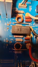
NAD 326BEE Channel Cuts Out. Replace Relay?

Hi,
I'm hoping someone can recommend a replacement relay for my NAD 326BEE to correct a problem with one channel cutting out, assuming that's actually my issue.

Background: I bought the amp used about a year ago. It was fairly pristine, but I still cleaned all the pots with Deoxit, checked for suspect caps, etc. It worked flawlessly for a while. Unfortunately, it developed an issue where one channel, mostly the left, would cut out on me. Fiddling with the volume knob a bit usually brought the channel back, so I assumed the pot was still dirty since it's motorized, almost completely sealed, and barely possible to get spray into. I tried cleaning it out again, and the problem disappeared, but returned about a week or so later. I'm not sure if cleaning it actually did anything, or it was just a coincidence that it stopped for an unusually long time afterwards. It's a very inconsistent issue, and impossible to replicate on demand. I finally got fed up enough to do some deeper research into it, but I can't seem to find any analogous problems specific to my exact model. I have, however, seen multiple mentions of issues with the NAD 306, which stemmed from an output relay that seemed prone to going bad, as is referenced in this thread. I figured it might be worth a shot to try swapping out the relay to see if it solves the issue permanently. Unfortunately, I can't find an exact duplicate of the current relay anywhere but an eBay retailer in China that's going to take over 6 weeks to get it to me. I've replaced relays before, but there was always an exact replacement available, so I'm hoping someone can recommend a product listing for a compatible relay at a Web site in the US with a more reasonable estimated arrival time. In case there's some issue with the attached image, the relay in question is a Massuse ME-11 with the text 012-2H4 and 8A250VAC. I believe the data sheet for the relay can be seen here. I'd really appreciate any suggestions for a replacement source, or any other suggestions on what the possible culprit might be. Thanks in advance.

Attachments

  • b.jpg
    b.jpg
    237.6 KB · Views: 381

Xduoo TA-10R tube amp makes a ticking noise when powered on (no sound)

Hello,

I purchased an Xduoo ta-10r tube amp about two years ago and it stopped working a year after the company warranty and they said it would be very expensive for them to fix.

They sent me an image asking if I could repair it myself, even offering to send me a replacement capacitor for it. Is it safe to attempt this repair? While I have opened electronics before repairs like this seem slightly dangerous to me. Plus, the metal chassis is closed with non-standard screws so I would need to make additional purchases to repair it.

Xduoo-ta10r Capacitor.png


They also said I could send it to an electronic repair shop. So, if anyone has any good recommendations on where to send it in Ontario Canada (From GTA). That would be very much appreciated.

Thanks for reading

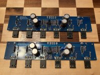
FS: Alpha Nirvana Class A boards

This is a pair of the Hugh Dean and XRK Audio designed
Alpha Nirvana 39 watts Class A boards,
Mounted on 5U heatsinks
They are Newly built tested and Sound Fantastic just add your favorite Dual Power Supply of between 26v to 28v and you are in business.
Asking $375prefer local pickup
Huntersville, NC area
I would also consider selling the boards without the heatsinks for $300

Hitatchi HA-7700 woe - one channel come and go...

Service Manual

I have unit that has an intermittent problem on Left channels that goes like:
  • It plays fine on "Main in" (there is a split between pre and main (4 RCA)) - so problem must be in pre/line section. Its a good power amp 🙂
  • L ch is silent using line in like AUX at power up and after a while, 1 minute..., it start to play
  • It usually crackles a bit when it starts to play, then it can sound fine for several minutes (5-20)
  • Then it can fade out and get silent - usually when signal level gets lower
  • It can be fine, then play distorted / crackeling for a minute or so.... then come back OK
  • It feels like it needs signal to work - like some bias is not there without signal?
  • Same on AUX and Tuner so I assume som common part downstream

Happy for any thoughts or ideas...

//

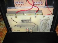
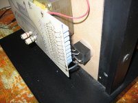
Audiostatic ES100 Sound Problem

Neither of my Audiostatic ES100 speakers will play high frequencies.I have a beautiful midrange but the sparkle is not there.
Since these are single panel I would think the problem would be in the interface.An ex Audiostatic employee thought it
could be a fuse or relay.I don't see a typical fuse but do see a small black box which could be a relay.Not sure how to test it.
Any help or thoughts would be truly appreciated.

Attachments

  • Audiostatic 5.JPG
    Audiostatic 5.JPG
    226.4 KB · Views: 268
  • Audiostatic 6.JPG
    Audiostatic 6.JPG
    206.6 KB · Views: 253

Parts for DIY Sony VFET (push/pull) amp

This is for the push/pull amplifier using two Sony VFETs per channel, as described here:
https://firstwatt.com/pdf/art_diy_sony_vfet.pdf

While putting something together for BAF, I found enough spare parts for another vfet amp.

So I have the following available:
  • A pair of pcbs: https://diyaudiostore.com/collections/power-amplifier/products/sony-vfet-circuit-boards
  • 2x 2SK82, 2x 2SJ28 vfets (they are not matched)
  • 2 pairs of Toshiba 2SK170BL/2SJ74BL jfets (4 jfets in total, ~8.7mA IDSS)
  • 2x 2SK2013 and 2x 2SJ313 mosfets
  • 2x ZTX450 and 2x ZTX550 cascode transistors
  • 2x IRFP240PBF and 2x IRFP9240PBF power mosfets
  • 10x TL431A shunt regulators
  • 4x blue LEDs for the amp PCBs
  • Resistors for the PCBs. The smaller ones are Vishay/Dale CMF/RN 1%. The 0.1R 3W current sensing resistors are Yageo/Vitrohm 1%
  • 4x 500R (Spectrol) and 4x 5K (BI Technologies/TT Electronics) single turn trimmers
  • 4x 1N4004 diodes
  • 8x 220uF and 8x 47uF Panasonic FM and FC capactors.
  • 4x TO220 heatsinks for the front end mosfets.

This should be everything you need to populate the two amp boards.

Please note these parts are from my personal stash and not from the essential or completion kits previously offered by DIYAudio.

You will have to source or make your own bracket (Please reference the drawing here: https://www.diyaudio.com/community/threads/sony-vfet-amplifier-part-2.276711/page-45#post-4581878 )
as well as supply your own mica/goop and mounting hardware.

This is not a beginner's project.

If interested, please PM me with an offer.

QUAD 306 - Distorted Output: Cap Replacement?

Hi everyone,

I recently bought a second hand Quad 306 and have been using it successfully with my Yamaha NS10m’s for about 4-6 weeks.
Sadly, the left output has now started distorting - quite badly, so it’s unusable - and I’m wondering what the best thing to do might be.

I’ve been hearing that it could be that the caps need replacing. Although, the seller - on eBay - said that he’d replaced them recently, but that’s not to say that he’s telling the truth or even if that’s the issue. I’ve also heard that replacing the TR8 (transistor?) could be a possible culprit.

Any suggestions?
Also, if it is the caps, is it something that someone with limited soldering experience can manage? (I’ve changed guitar pickups etc).

Thanks!
James

Pair of SB Audience NERO 6" Neodymium Pro Midrange Drivers

I have a used pair of SB Audience's BEST Midrange (NERO Line) for sale.

Retail is $271.95 CAD EACH ($543.90 CAD + Taxes per pair) at Solen.ca currently

https://www.solen.ca/en/products/nero-6mrn150d-16cm-paper-cone-pro-midrange-8ohm

It is the NERO 6MRN150D Neodymium model

Driver Features:

6" (162.7mm) Paper Cone Neodymium Pro Midrange
98dB / watt Sensitivity
150 Watts Continuous / 300 Watts Peak
Rated range 200 -10,600 (more realistically I have measured it pretty flat from 350 - 3.5kHz)
8 OHM Features Proprietary cone paper material with graphite
Flat foam surround for best midrange reproduction
High grade (Powerful - BL 13) neodymium magnet
Shorting ring in motor system for reduced distortion
CCAW voice coil for reduced moving mass
Minimum damping fiber glass voice coil former
Cast aluminium chassis

Condition-wise its an 8 overall
Paper / graphite cone / flat foam surround rated a 9
A few marks on cast frame / Mounting screw holes (See photos for reference)

Selling this PAIR for $169.95 USD with FREE Shipping in Canada & US

Attachments

  • Nero 1.jpg
    Nero 1.jpg
    74.4 KB · Views: 112
  • Nero 2.jpg
    Nero 2.jpg
    100.4 KB · Views: 110
  • Nero 3.jpg
    Nero 3.jpg
    96.9 KB · Views: 112
  • Nero 4.jpg
    Nero 4.jpg
    55.8 KB · Views: 94
  • Nero 5.jpg
    Nero 5.jpg
    88.1 KB · Views: 106
  • Nero 6.jpg
    Nero 6.jpg
    84.2 KB · Views: 100

Recognizing part maybe TVS diode?!

Hi guys
I'm missing SA501 and SA502. Are these a TVS diodes ? They were badly burnt but I could still read something like 3 stripes red green red. I highly doubt it's a 3 band resistor of 2.5KΩ. They are being used in the preamps section in between the RCA shield and the secondary ground of the transformer. I 've also found that the traces from the secondary gnd to the RCA shield have been blown up.
The amp is Philips xp480. I do not have the schematics.
Any ideas ?

Attachments

  • diode.jpg
    diode.jpg
    797.5 KB · Views: 166

2x12" full range build

Hello,

I'm about to build a box for two fane 12-250tc that looks like the first picture (150l, 40hz), but something bothers me. By putting all my box characteristics in a software like winISD or speakerBoxLite and looking at the cone displacement graph (second picture) it goes terrifyingly high.
I first thought that these drivers just can't handle such a big box but then I found this guy's build (link) with even more volume (90l. per driver).
Then I looked at fane's recommendation and they recommend a max of 75l. per driver but even with these numbers in simulator cone displacement gets crazy.

May it be that fane gives an xmax that correspond to absolutely 0 distortion (which I don't really care, it's for partys) and xmech is way higher ?
Or they expect us to not send full power with big boxes ?

Some help or ideas would be very appreciated 🙂


IMG_0145.PNG

1692649497019.png

CSR8645 Popping Noise

Hello everyone,
I have a csr8645 module attached to an breakoutboard with AMP.

https://de.aliexpress.com/item/3283...t_main.491.27b35c5fVA1k2c&gatewayAdapt=glo2en

I've put in in my old car radio and it works but when I pair bluetooth you hear popping/crack noise. Also when I start/stop streaming audio you can hear the noise after 3 seconds.
Other users had the same problem in this thread.
According to a user the problem seems to be that the chip disables the ouput stage when it doesnt recieve any audio stream.
I have a csr-spi programmer and I played around with a lot of settings (i.e. disable low power codec) but I could find a solution. Also using the mute pin of the board results in popping noise.
Does anyone know a solution how to keep the codec alive eventhough its muted on the sender? Can I solder some components to the amp circuit which could prevent the popping noise? Any help would be very much appreciated.

Review of Acoust-X sound Damping Paint

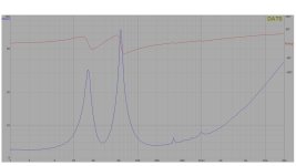
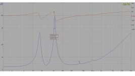
Attached is my impedance sweep of a Satori 9.5" WO24P 8 ohm woofer. This sweep was taken using Dats 3 with the woofer installed in its enclosure. As you can see, there are 3 distinct blips to the right of the woofer resonance curves that catch your attention. The blip farthest to the right at 1Khz also shows up in the free air sweep (not attached) so has nothing to do with my enclosure. I have no idea what this blip is from, but since it's well past my target crossover point of 500hz, I'm ignoring it. I'm not sure what the middle blip at ~700Hz is from, but I'm guessing it's my 6" long x 2" diameter vent tube. The 3rd blip at ~364Hz would appear to be a standing wave from my woofer enclosure. The enclosure is a roughly 1.4 cu ft cylinder with a 13.2 inch inner diameter.

I have no real idea if the amplitude of any of these blips warrant attention, but I decided to try to cut down the one at 364Hz as it's within my target crossover frequency. My first attempt was to install rockwool to see how well it reduces the standing wave. The rockwool I have is very fragile and didn't conform well to my enclosure. I covered the bottom and about half way up both sides of the enclosure and took another sweep. The amplitude of the blip at 364hz was reduced by about half, so I believe it is my enclosure causing it. I attempted to install the rockwool to the enclosure top, but only caused it to break into multiple pieces. At this point, I did more research and decided to remove the rockwool and try Acoust-X paint by Acry-Tech.

The first thing to know about this paint is how to open it. It has instructions on the lid, but they're not clear at all. What they want you to do is push down in the center of the lid while simultaneously prying up on the outer lid rim with a screwdriver. This works, but takes a lot of force to open. It can also be messy so wear gloves even when just opening the container. You should also wear gloves and ensure good ventilation when applying as the MSDS for this stuff has several health warnings (Including potentially being a carcinogen).

Next I used a small paintbrush to apply to all the inner enclosure surfaces. This paint is thick - much like a good thick milkshake. It does not go on well by using brush strokes. You're better off dabbing it on as brushing seems to just push it around rather than coating the surfaces. I put on 1 coat and left to dry. The container gives no directions relative to drying time, so I returned to inspect the coating after 30 minutes, 1 hour, 5 hours, and 24 hours only to find that the coating was still wet. I let it dry another 24 hours (Still wet), but applied the second coat anyway. In fairness, I was applying the coating in my cool basement, so that could be part of the reason it wasn't curing well. After applying the 2nd coat, I placed a small fan blowing into the enclosure. The fan was the trick as the 2nd coating was dry after 24 hours. I ended up putting on a 3rd coating to cover a few spots I missed and once again used the fan to dry (Waiting another 24 hours).

The instructions say to clean up with water, which works well. The brush is easy to clean and can be reused several times as a result of the easy water cleanup.

The 2nd attached file shows the Dats 3 impedance sweep of the woofer after applying the paint. It appears to have narrowed the frequency a bit, but also increased the amplitude. Again, I don't know how big of a problem this is, but it appears the sound damping properties of the Acoust-x paint did not improve (and may have made worse) the standing wave (If in fact this is a standing wave) problem.

I'd be interested to hear others thoughts on this and if you've tried this paint

Attachments

  • Woofer Impedance Installed Before Acoust-x.jpg
    Woofer Impedance Installed Before Acoust-x.jpg
    73.9 KB · Views: 165
  • Woofer Impedance Installed After Acoust-x.jpg
    Woofer Impedance Installed After Acoust-x.jpg
    77.7 KB · Views: 150

Resistors - Mundorf Supreme - very disappointing

I've just replaced the resistors in my three way speaker. I've moved from standard ceramic wire-wound types to Mundorf Supremes at a cost of £90...

I was expecting the sound to be much better, however, it is much worse - very disappointing. There is a slight increase in detail across the mid and treble - if I wasn't so familiar with my test tracks I wouldn't have noticed this. However, there is now considerable sibilance and treble 'wispyness' which wasn't there before. It is not making for a pleasant listening experience.

This may be that 'burn in' time required, if that is a thing. But as it stands I will chalk the cost up to experience and switch back to good old cheap ceramics.

Building 21" sealed subwoofer w/ PD.21 drivers

Hi, I want to build some really subs that go down very low without sounding muddy.

I came across this design for a 21" sealed subwoofer.

  1. https://www.humblehomemadehifi.com/download/Humble Homemade Hifi_Serious Sub.pdf
  2. https://www.humblehomemadehifi.com/library/Humble Homemade Hifi_CAD_Serious_Sub.pdf

I like the approach and the designers thinking. I've got the space and making this would be cheaper than anything I'd consider buying.

The original sub bass driver used in the design was the PD.2150. That has since been discontinued and they now make the PD.2155 in a 1N (Neodymium) and 1F (Ceramic) variation. Although stock is limited on both of these.

  1. https://www.precision-devices.com/products/all-products/pd-2150/ (discontinued)
  2. https://www.precision-devices.com/products/all-products/pd-2155-1f/
  3. https://www.precision-devices.com/products/all-products/pd-2155-1n/
Is there anything about these newer version of the PD.215X which make it more or less suitable for this use? I know I'll have to adjust the designs slightly to hit the 0.5Qtc specced in the design.

If they're both fine, is one going to be better suited than the other? I note the Ceramic version has a lower state frequency range (28 vs 30) but a highly higher f0 (35 vs 33).

Any input about driver suitability for this project is greatly appreciated as well as any thoughts on this particular design concept.

Cheers

new Astera based cabinets in Corian

6 years ago I started building my current loudspeakers based on the astera. I used high quality MDF as cabinet material, the build can be seen here,
https://www.diyaudio.com/forums/multi-way/250040-diy-2-based-diapason.html

The loudspeakers are still used every day in my listening room and I am still very satisfied with these loudspeakers.
Last year I build a record player with a plinth of the material Corian, it was a great improvement relative to my previous player, which was made of veneered plywood. That made me thinking of another built of my current loudspeakers out of corian
a few weeks ago I started the built, I still have the drawings that I made 6 years ago, these are based on a thickness of 25mm, corian plats are 12.5mm thick, so I had to glue 2 plates together to achieve 25mm thickness.
The build still in progress, and I'll give you some pictures

Attachments

  • foto0.jpg
    foto0.jpg
    878.6 KB · Views: 384
  • foto1.jpg
    foto1.jpg
    754.3 KB · Views: 435
  • foto3.jpg
    foto3.jpg
    960.7 KB · Views: 406
  • foto4.jpg
    foto4.jpg
    974.3 KB · Views: 380
  • foto5.jpg
    foto5.jpg
    512.1 KB · Views: 376
  • foto6.jpg
    foto6.jpg
    702.2 KB · Views: 293
  • foto7.jpg
    foto7.jpg
    582.3 KB · Views: 298
  • foto8.jpg
    foto8.jpg
    837.2 KB · Views: 294
  • foto9.jpg
    foto9.jpg
    753.1 KB · Views: 432
  • foto10.jpg
    foto10.jpg
    520.2 KB · Views: 322

Pearl 2 Phono Preamp PCB Pair - Australia

Hi,

I've got a pair of the Pass Labs / Wayne Colburn "The Pearl TWO" PCBs for sale, the well known and much loved Phono Preamp.

I heard this preamplifier and a friends place years ago and was very impressed and ordered the boards. They were professionally made up from the gerber files that were available some time ago but have been sitting in a box for years. However, Looking at my huge list of to do projects, its time to aknowledge they aren't going to be used and move them on. I soldered in the heatsinks years ago, for whatever reason, but other than that the boards aren't touched.

Have the pair for $40AUD via bank deposit with postage included within Australia.

Cheers -MSNC

IMG_20230823_175313.jpg


IMG_20230823_175327.jpg

For Sale Modushop Deluxe 4U Chassis with 10mm silver anodised front panel

Need to raise some cash so postponing planned build of M2X.
I have a brand new Deluxe 4U chassis in its box, unopened. 300mm front to back. Has internal baseplate and pre-tapped heatsinks and rear panel.

Looking for £290 delivered in UK only please.

Which is almost £100 saving once shipping and import taxes are aded on.

https://modushop.biz/site/index.php?route=product/product&product_id=777

Perfect for any of the First Watt designs.

Side-firing woofers and crossover frequency in the near-field

In one of my projects, it would be convenient to mount the woofers on the side of the cabinet, rather than the front. However after searching the forum I've found three different opinions of what crossover point makes that arrangement acceptable. One says low enough that the radiation is 4pi, another says low enough that the woofers are located within 1/4 wavelength of the mids to produce one coherent wave, another says less than (around) 80hz where we lose the ability to judge direction/location easily.

The first two would be easy enough but 80hz is much lower than I intend, if that were necessary for seamless results then I would definitely prefer to mount the woofers on the front baffle instead. Which is possible but would make the cabinets wider than wished for their desktop near-field application. And as that implies, I'll also be listening to these at only a couple of feet distance, so slight positional differences might (in some cases) be much more apparent from close up.

Can anyone help enlighten me as to how low I might truly need to cross if wanting to safely use side-firing drivers in a near-field situation?

Thanks,
Kev

EV HR9040 with modern compression driver - will it work?

Ladies and gentlemen,
i am asking on behalf of a guy i met in another german forum, i am not the lucky winner owning the big horn here:
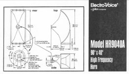
EVHR9040-Drawing-Capture.JPG
the precise question is the following: did anyone here made it to combine this large horn with a modern compression driver like the B & C DCM 414 or something even better like a BMS coax driver? Many thanks in advance for the interest about the question and best regards,
Stefano

Wurth inductor

Does anyone try these in a PSU for a solid-state amp?

I am contemplating a CLC design with a single large inductor bank (88,000uf) followed by 4 channels R/L and +/- 24 vdc respectively each with a separate inductor and 33,000 uF cap feeding the output. Each channel should draw about 500mA. I've only built supplies for tube amps and am not too sure what the issues are with a design that doesn't include a 'huge' 4 H inductor and much less capacitance. I ran the simulation in PSU II and it looks great. This seems a great option at a cheap price. I was trying to find something similar at 2uH but this seems like it would work. I know with inductors I need to be concerned about saturation but this looks fine at this current at least if I understand the specs.

Wurth Leaded WE-FI Toroidal Choke 150uH 5.4A 42mOhms https://www.mouser.com/ProductDetail/710-7447055

Looking for Equivalent to Moxie (thermistor) TS3-85-B3

This part is used across the biasing transistor of APT 1 amplifiers to reduce gain if the heatsink exceeds 85 deg. C, in which the resistance falls from 130-150kOhms to less than 100 Ohms, to reduce the input signal.

Of course, the part is no longer produced, and my attempts to get one of the original manufacturers to help me find a suitable replacement haven't yielded results. Is anyone familiar with a replacement to this part, which is missing from the amps I'm working on? The original is the one with the tab, but I can adapt mounting for other types if they are electrically similar.

Thanks!

CanthermTS385B3.jpg

Purifi 6,5' 6+ W29TXN-8 CNC Waveguide 2,5 ways

Here are the speakers I designed in the last months.
It's a 2,5 ways design with two 6,5' Purifi Midwoofers and a TW29TXN-8 SB Acoustics tweeter.
The front plate is made by CNC milling, the internal volume is 38L each ( for both midwoofers ).
I placed two Dayton Audio 8' passive woofers for each box, tuned at 32Hz.
As I don't like the original SB used for the BNWG version, as, for me, it's too deep and with a too narrow dispersion angle, I designed and printed a custom adapter with an HP JetFusion printer.
In the past I made some printed waveguides and I found out that, in a standard room and, mostly, if we don't listen to the speakers just in a single fixed position, the lack of high frequencies given by a low dispersion angle ( let say less than 120° ) is something I don't wanna have.
It seems like ( and the measurements confirm it ) as a waveguide becomes deeper and narrower, the distortion at high frequency increases.
The adapter plate size is critical as there is a very little space to fit the screws and the waveguide throat ( and basically that's why SB makes a so deep WG, in my humble opinion ).
The waveguide is CNC milled in 1 piece with the front baffle but I'm gonna make some CNC waveguides which can be mounted on every baffle if somebody is interested in.
It seems like Purifi also followed the same rules with their new tweeter waveguide design, modeling a less deep, wider waveguide.
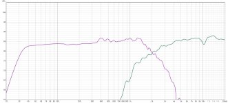
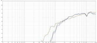
Here are the first measurements, maybe if someone is interested in I can also make some plate + CNC WG kits.
In the measurements you can find both the first and the second midwoofer response and than:

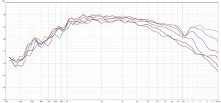
Pict N°1 : TW29TXN-8 + WG response at 0-15-30-45-60-75 degrees
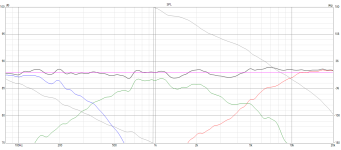
Pict N°2 : the tweeter with three different filters ( 1.8uF, 2,7uF+0,47mH, 2,7uF+0,55mH )

That dip around 10KHz is given by the inner WG throat diameter or bu the wide tweeter surround.
I don't actually think it is something relevant or audible because it's just a point discontinuity, just something not so good to be seen on a graph.
The out of axis behavior is definitely better than the SB Acoustics WG for me, which I think matches better my needings.

Regards!

Attachments

  • 20230611_175342.jpg
    20230611_175342.jpg
    399.4 KB · Views: 289
  • 20230716_182442.jpg
    20230716_182442.jpg
    322.9 KB · Views: 249
  • 20230716_184423.jpg
    20230716_184423.jpg
    342.7 KB · Views: 213
  • 20230716_185850.jpg
    20230716_185850.jpg
    309.4 KB · Views: 233
  • 20230716_192310.jpg
    20230716_192310.jpg
    336.4 KB · Views: 244
  • 3.jpg
    3.jpg
    169.8 KB · Views: 257
  • 2.jpg
    2.jpg
    167.8 KB · Views: 252
  • 1.jpg
    1.jpg
    175.9 KB · Views: 264

I'm cursed...

Opened up my box of brand new Manger MSWs today to measure them on my WT3. Got once clean measurment and saved it to my PC. Then I repeated the impedance sweep and it looked funny.

Long story short, one of the VCs decided to open up and quit just from 2 lousy low level measurments. Its things like this which make me want to quit this audio crap. It's bad enough my health is garbage. Everything is seem to touch is turning sour.
  • Like
Reactions: Ixnay

Schematic Needed on older DH-500 (PC-9A)

I have an older Hafler DH-500 with a PC-9A power board instead of the PC-9C that I have found on the online manuals. Does anyone have the earlier manual or the schematics? The board is in pretty good shape so I think I can read all the resistor codes, but the diodes are all most all dead and I want to be careful and sure.
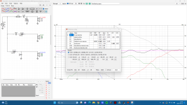
I did notice that Fantasia audio provides the schematic (for both the PC-9c and PC-9a) with the upgrade kit for the PC-9 on ebay, but since I probably have the replacement parts in stock, I hesitated to buy it.

Thanks in advance!!

Bass Box Porting and Overloading Questions Peerless 830886

I have a question about the 830668. I'm kind of dumb and I need a few really basic questions answered, namely "Are three things going to be a problem if I actually build this?" I built a bass box in VCAD. Their new tools are awesome. Kimmo just needs to figure out how to integrate all of them at once so I don't have to keep flipping windows and importing data.

I was doing the usual paint-by-numbers sealed enclosure with EQ. I run into an excursion problem, and my first thought is "Can't I get a lot more power handling by throwing a port in there tuned to driver Fs?" Surely the displacement should be massive and solve the excursion problem! So I kept going with this monstrosity that may never fit together, EQ'ing the medium box flat to 30hz. Then I thought I could do better if I ignore the power handling aspect. So here's the three problems with three dumb questions:
1: Can I ignore power handling requirements if the port is moving the air, not the driver? Similarly, does the driver still use the power even though it doesn't move? I imagine it does to reverberate air, not itself.
2: Is the impedance an issue outside of amplifier selection? It hits 3ohm across most of the sub-bass spectrum.
3: Will everything explode in this configuration?

In very stupid terms, I have colored the driver into the lines. The dark blue fits into that light blue shape at 200W, the excursion is just barely passing xmax, and the vent velocity is manageable if I ignore that we only live in three dimensions. The following represents worst case.
View attachment 1205671
View attachment 1205669View attachment 1205672View attachment 1205673View attachment 1205668

The original sealed box was limited to 95dB SPL. Boosting, cutting, and preamping until the response was flat with EQ. Hence the hair-brained idea. The light blue vs dark blue lines highlighting my completely unfounded theory on porting. Both are maximums, the lighter line is following the natural rolloff, the darker line is what I am afraid I would have to flatten it to if I wanted to reach an F3 of ~30hz. The red is my ultra-optimism that I won't blow the voicecoil.
Screen Shot 2023-08-23 at 09.48.37.png


Here's the sealed configuration:View attachment 1205687

Help with my first speaker build (3-way)

Hello!

I've been wanting to get into DIY for a while now, a few days ago i found a very good deal on some Scan-Speak elments that i couldn't resist. My DIY journey shall begin!

Drivers Scan-Speak
Tweeter (pair): D2905/950000
Mid (pair): W15/8530K00 Revelator
Woofer (pair): W21/8555-00

Got it all for under 340 EUR including a bunch of crossover parts as well, so not all too expensive for a first build i guess.

I've been fiddling with VituixCAD for a few hours now (I might also try Xsim later to see which one I prefer). Honestly, I dont really understand what I'm doing at the moment. I've assembled some components and tried adjusting their values until I achieved a smooth frequency response (within about +- 1-2 dB range?). However, it's clear that there's more to take into consideration. I would greatly appreciate a lot of feedback!

I plan to delve deeper into the enclosure features in VituixCAD and also fine-tune the x, y, z parameters for the drivers once I've settled on an enclosure design (I assume this affects phase?). According to WinISD, the woofer's f3 will be 29 Hz in a 50-liter enclosure. Maybe I should aim for a slight boost in the bass because of baffle step loss? Or will room gain compensate enough?

I suspect that the crossover point for the mid/tweeter might be a bit high. I suppose the crossover points are in phase due to the 6 dB summation?

My intention is to measure each driver within the actual enclosure and then base my design on the actual frequency response curves (or is that a bad idea?). For now, I'm primarily focused on learning the process of designing a crossover. I'm aware that my capacitor values seem rather high and could potentially be expensive, but the overall number of components appears to be relatively low, so perhaps it balances out.

I would greatly appreciate your feedback as I'm struggling to interpret the information presented by VituixCAD. Are there any red flags? Any positive/negative aspects that I should pay special attention to? Thanks for your time!

//Jocke

Skärmbild 2023-08-16 195532.png


Skärmbild 2023-08-15 214035.png

Attachments

  • freqresponse.png
    freqresponse.png
    23.3 KB · Views: 108
  • Skärmbild 2023-08-15 214012.png
    Skärmbild 2023-08-15 214012.png
    93.8 KB · Views: 102
  • Skärmbild 2023-08-15 213850.png
    Skärmbild 2023-08-15 213850.png
    79 KB · Views: 118

aluminium sheet in UK

I want to replace the front and back of a small-ish case and re-drill them for a new project. wxhxd 220x55x5 and 210x45x2 so not large. I've looked at a few sites that offer cut aluminium sheet at reasonable prices but then cane me on delivery. So £15-20 for sheets and slightly more for delivery and at that price I might as well buy a new case from modushop. It'd be useful to have a supplier for these things.

Anyone in the UK have someone they've used before?

Introduction to PCB design for DACs

Hi Guys!
I'm happy to share my first video, for the DIY HiFi channel. It's a podcast with Zach Peterson, whom you might know from Altium Designer's YT channel. I think the videos gives the fundamentals, on which you can start messing with DAC PCBs. I hope you'll like it! The feedback is appreciated.
Apologies for my bad accent. It's not that bad usually, it's just me being nervous. You don't talk to guys like Zach every day 🙂

Login to view embedded media

PCB design: a primer?

I'm a total novice to electronics, I know my way around basic analog circuitry (which is why I managed to design a guitar amplifier) but I have no idea where to start with PCB design.
I'm using KiCAD and I've drawn the schematic (simulates well in LTSpice); now, some info on how to translate the schematic into a PCB would be nice.

I would be using through-hole components (because how the hell am I going to work with SMD anyway?) and I'd like the amplifier to be as quiet as possible, no ground loops (OK, use a star ground, or at least a "one-way ground rail" connecting stages sequentially), no oscillations, etc. I know that with a single-layer PCB you can't really use ground planes, and ground planes can be sort of overkill when it comes to audio anyway, but where can I start?

PVC pipe speaker?

Hi,

I am planning on making a jbl speaker alternative using the "Dayton Audio TCP115-4" and the SB Acoustics "SB12PFCR-00 Passive Radiator" in a 1.6 liter box with a tweeter i have yet to choose and i have a few questions about my plan:

  • Could i acoustically use a pvc pipe as an enclosure for this
  • Can someone please check my calculations if they get the same results in winisd? I would much appreciate it!
1692466786052.png


thanks for reading and hopefully replying!
Nanno Haasjes

Explanation for horizontal beamwidth of JBL 3252(N) ?

Hello,

According to JBL, the 3252(N) uses dual 15-inchers crossing over to a 1-inch horn at 2kHz. However, it is also shown to have a horizontal beamwidth of not less than 90* across the 1kHz-10kHz range. What could be a mechanism that enables this kind of beamwidth, considering the fact that a 15-incher at 2kHz is maybe 60* (-6dB) at best ?

Thanks in advance.

1692511091933.png

Anybody with a Tigersaurus to sell and able/ willing to ship to the UK??

Good afternoon all,

On the basis if you don't ask nobody will know what you want I'm asking the question.

Basically it's a two part question:-

1. Does anybody have a Tigersaurus, working or otherwise, they're willing to sell and (the much more difficult part)

2. be willing to box up and get shipped to the UK.

The shipping bit won't be cheap but one step at a time......

Regards

Richard

For Sale 18Sound 6ND410 MIDRANGE

18Sound 6ND410 MIDRANGE, used

Small cosmetic defects at the level of the outer seal of one of the two speakers, see the pictures. Used only for hifi.
The price for the pair is: 140€
Shipping to europe is 25€, international shipping is 55€, if you want insured shipping please ask for the price. Payment by PayPal, satispay or bank transfer in advance.
my email is franco.cauda@gmail.com

Attachments

  • IMG_9604.jpeg
    IMG_9604.jpeg
    570.7 KB · Views: 116
  • IMG_9605.jpeg
    IMG_9605.jpeg
    526.7 KB · Views: 118
  • IMG_9606.jpeg
    IMG_9606.jpeg
    506.1 KB · Views: 169
  • IMG_9603.jpeg
    IMG_9603.jpeg
    575.9 KB · Views: 107
  • IMG_9600.jpeg
    IMG_9600.jpeg
    704.3 KB · Views: 118
  • IMG_9602.jpeg
    IMG_9602.jpeg
    612.4 KB · Views: 133
  • IMG_9601.jpeg
    IMG_9601.jpeg
    605.2 KB · Views: 124

Stacking rectifier boards?

Due to layout & space issues I may stack the rectifier PCB's for a pos/neg PSU in a preamplifier. This would put one bridge directly above the other on another "deck".

In order to avoid coupling, cross-talk, field interaction, etc. I was thinking a spare 20mm space between the TO-220 rectifiers and the board above, so, 40mm risers stacked on top of the lower board.

The rectifier output is +/-19VDC with a max load of around 200mA and the caps are screw terminal right next to the bridges.

Does this seem a good plan? Any downsides that could affect the quality performance of the result?

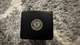
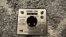
For Sale Hashimoto Choke C-15-200CH

Hashimoto Choke C-15-200CH for sale. Bought for a project but never able to finish it up. So available for sale. Asking $175 USD, will ship anywhere at buyer's expense.

Let me know if you have any questions.

  • Inductance & DC Current: 15H - 200mA
  • Max. DC Current: 240mA
  • DC Resistance: 130 Ohms
  • Max. AC Input Voltage: 600V Max.
  • Min. Operating Current: 40mA Min.

Attachments

  • IMG_4701.jpg
    IMG_4701.jpg
    411.5 KB · Views: 95
  • IMG_4700.jpg
    IMG_4700.jpg
    451.7 KB · Views: 100
  • IMG_4694.jpg
    IMG_4694.jpg
    414.9 KB · Views: 89

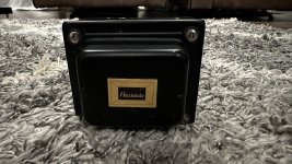
For Sale Hashimoto Power transformer PT-95F

Hashimoto Power transformer PT-95F for sale. Bought for a project but never able to finish it up. So available for sale. Asking $150 USD, will ship anywhere at buyer's expense.

Let me know if you have any questions.

  • Primary Voltage - 120V (F)
  • Secondary Voltages - 280V-250V-220V-0-220V-250V-280V: 0.16A AC (220mA DC with Full Wave Rectifier)
  • 0-6.3V: 2A ( x 3)
  • 5V: 3A

Attachments

  • IMG_4698.jpg
    IMG_4698.jpg
    386.8 KB · Views: 101
  • IMG_4699.jpg
    IMG_4699.jpg
    393.7 KB · Views: 105
  • IMG_4696.jpg
    IMG_4696.jpg
    470.6 KB · Views: 93

RCF amplifier SMPS mosfets keeps blowing

Hello everyone!

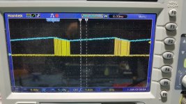
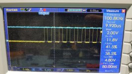
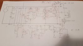
I am having issues with an RCF amplifier SMPS. When switched on, the power supply mosfets (P20NM60) always going to short-circuit or exploding, sometimes killing the gate driver circuit, the driver ic (S21531D) and the short circuit protection part. I measured all the passive and remaining active components around it, and it seemed good. I checked the secondary side and there is no short circuit. The primary DC bus ok, around 310V. So I replaced the faulty components, the driver ic, the mosfet driver circuit, and the mosfets. But I didn't succeed, the mosfets became short-circuited again. So I tried to redraw the schematic of the primary side. Sorry for the poor drawing!

I replaced again the control ic, the entire gate drive circuit, the control ic's auxiliary and main power supply voltage regulator circuit, and the LMC555CM timer ic, which is part of the short circuit protection circuit. Almost everything, except for a few resistors and capacitors... (The replaced components are marked in red) So I started the power supply connected in series with a light bulb for current limitation, but first without mosfets and I checked the bottom mosfet gate control signal on an oscilloscope. It seemed good, the frequency was 100kHz and after a few cycles it breaks and restarts, which is understandable, since the control ic only receives voltage from the starting power supply, which does not provide enough current for continuous operation. I soldered in the new mosfets, but no succes. The mosfets goes into complete short circuit again. 😕

I was curious that there was no short circuit in the primary winding of the transformer. I measured the inductance of the primary winding in the circuit, which was 1.95mH. So I don't think the transformer is shorted.

What could be causing the problem?🤔 Has anyone encountered a similar phenomenon?
If you have any suggestions, I'd be happy.

Best regards!

Attachments

  • 20230812_223745.jpg
    20230812_223745.jpg
    414.6 KB · Views: 267
  • 20230812_223858.jpg
    20230812_223858.jpg
    512.4 KB · Views: 219
  • 20230812_224202.jpg
    20230812_224202.jpg
    351.4 KB · Views: 289
  • 20230812_230711.jpg
    20230812_230711.jpg
    228.2 KB · Views: 334

  • Poll Poll
What compromises would you make?

Which of the following parameters would you let go of first?

  • maxSPL

  • low-end

  • group-delay

  • distortion


Results are only viewable after voting.

It's time for a little thought experiment.

Let's say you've settled on a certain active loudspeaker design.
The dimensions are set, the choice of drivers are chosen as well.
It's not possible to make any changes there.
Also the type of system is fixed.
For those who find this a little bit to abstract, lets just settle on a closed box system.
Let's say it's just a subwoofer or FAST system for now (I might make another poll for 2-way or mutli-way systems)

However, you want to squeeze out a little more performance out of the system.

In this world, nothing is for free, so this means we have to compromise.
Which parameter would you let go of first?
Aka, do you think is least important so you can improve the others?

maxSPL, low-end (how low the speaker will go), group-delay or performance in distortion?

Ideally tell us why as well with context. 🙂

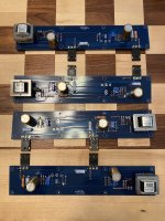
FS: F6 & F4 built boards

For Sale:

1 set of FW clone boards, built and tested.

SOLD - Asking $75 for the F4 pair. F4s was built using boards, MOSFETs and matched quad of JFETs from the store.

SOLD - Asking $100/pair or $175/quad for the F6 boards. F6s were built using boards, parts kit and matched octet of JFETs from the store.

All boards biased up and worked just fine prior to removal. Sold as-is.

Shipping to anywhere in the US included in the asking price. Paypal preferred.

Attachments

  • IMG_1210.JPG
    IMG_1210.JPG
    706.4 KB · Views: 156
  • IMG_1212.JPG
    IMG_1212.JPG
    726.6 KB · Views: 148

Preamp. Low power for one 9V battery

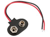
When using battery supply there is best to only use devices with low current consumption.
This way the battery will last much longer.
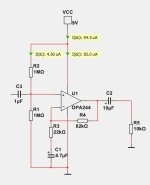
The circuit shown uses OPA244, a very low power opamp.
The idle current is only 50uA = 0.05mA.
There are opamps with even lower current.
But OPA244 was chosen as it has acceptable GBW, 430kHz and also has fairly low THD distortion.

The circuit has a voltage gain of 4.7.
The THD is 0.00006%.
The upper bandwidth is like 100kHz.

Attachments

  • 9Vconnector.jpg
    9Vconnector.jpg
    11.5 KB · Views: 159
  • OPA244 amplifier.jpg
    OPA244 amplifier.jpg
    19.7 KB · Views: 164
  • Like
Reactions: NanoFarad

Strange DC on volume pot - Sony TA-F550ES amplifier

Hi there,

Upon cleaning the controls and switches on this amp, the volume control became scratchy on the left channel. Testing shows 3.7V DC on the volume pot and the balance control (volume all the way down and balance centered).

What I'm describing hereon applies to the left channel; right channel is OK and the amp plays both channels fine (except for the volume scratchiness) and works fine. DC offset is acceptable (30 and 40 mV) and the bias is to spec. The service manual is too large to attach here. It's at hifiengine - dot -com/manual_library/sony/ta-f550es.shtml . The amp in questions is a Canadian model.

It seems the corroded selector switches (sound was cutting off and contact cleaner wasn't enough; I had to take them apart to shine them) were impeding DC.

Measurements and notes:
- Measurements done with no source connected.
- The 3.7V DC at the pot is also present at the line input selected. Shorting the selected input reduces it to 0.3V.
- The DC seems to originate on the Selector board as disconnecting it totally from the other boards (except for bus EH3 to power it from the Main board) does not remove the DC; to the contrary, this puts 35V DC almost everywhere on the Selector board.
- DC voltages at EH3 read (from 1 to 5): 0V - 1.1V - 0V - 0.8V - 51.3V.
- Turning both Direct-in and Mute on reduces DC on the pot to 0.7V.
- Turning both Direct-in and Subsonic on reduces DC on the pot to 0.0V BUT puts 12.8V on the balance control.
- All voltages measure from chassis ground with DMM.
- The Selector board is capacitor coupled to the EQ board and there is no DC present at R419 (or R469 on the R channel). So DC cannot be coming from the Phono stage on EQ board.
- DC at the negative of C302 is -0.4V (close to the specified -0.3V on pin 15 of IC301) so this cap is not leaking. C352 on R channel is similar.
- There is rail coming into the Selector board to power the LEDs and their drivers; however, the schematic does not show any way for this to get onto the volume, balance or tone circuits.
- I also removed the Muting board completely in case it's infiltrating DC, but that didn't resolve anything.

I can't figure out where the DC at the volume, balance and tone section of the Selector board is coming from.

Your thoughts and suggestions would be appreciated.

Regards,
Bill

For Sale NP First Watt F6 & F5turbo with Toroidy TTSA0500

Due to health issues, I can't complete this project so it's here for sale.

I originally bought this bundle from someone on this forum, the original thread has some details and pictures https://www.diyaudio.com/community/...rbo-transformer-required.386105/#post-7034293. They also included a full set of matched mosfets for the F5T which were not included in the original thread. I purchased a Toroidy TTSA0500 to use with it.

I originally paid £500 and now that I've included the Toroidy as well, I'm after £550.

Based in Bristol, UK.

Currently looking for UK sale, ideally collection due to weight.

Subwoofers, MiniDSP and compressor settings

I'm playing around with the compressor in MiniDSP Flex to avoid my subwoofer power amps clipping and/or go into voltage- and current-protection. They do clip very hard, and when a protection event occur they tend to produce a very loud "click" sound from the speakers. The MiniDSP also clips quite hard.

My power amps clip at 3.46V input, while the max output of the MiniDSP is 4V, a relative difference of 1,26 dB

The subwoofers are crossed over at 80 Hz.

My current compressor setting is like this:

1691398487948.png


Any thoughts/suggestions.... ? Do the attack and release times make any sense?

Input on 2nd try at active 3-way sbacoustics build (ceramic series drivers)?

Hello!

A couple of years ago I tried building an active 3-way with hypex FA123 with the drivers:

8″ SB23CACS45-8 / Ceramic (https://sbacoustics.com/product/8in-sb23cacs45-8/)

5″ SB15CAC30-8 / Ceramic (https://sbacoustics.com/product/5in-sb15cac30-8/)

SB26CDC-C000-4 / Ceramic (https://sbacoustics.com/product/sb26cdc-c000-4/)


I failed on the finish line, glued the box together wonky and then a lot of life stuff happened and I lost interest. The box was a constrained layer damping cabinet with a special swedish glue made for that purpose.

I am debating either selling all the stuff (don't know if I could get it sold) and just buying some cheap speakers (looking at the kali in-8) or trying again, but this time a simpler construction.

I tried calculating the volume for a sealed cabinet for the 8 woofer and used winISD and got around 44l for a wtc 0.707, and also tried the calculator on loudspeakerdatabase and got 39liter? I am confused.

My question is what software to use to calculate this if they all show different? What volume would you guys go for and why? For both the mid and the woofer respectively? I read up a bit on it and want a flat FR (my goal is studio monitors for my hobby music studio) and that seems to be qtc .707.

Sorry for the wall of text but would really appreciate some input! Seems like i have forgotten everything i knew about speakers in just 2 years...

Attatching a pic of my previous failed build for size-reference of what I'm after

Attachments

  • 20210425_214833.jpg
    20210425_214833.jpg
    289.4 KB · Views: 133

room's acoustic treatment

Hello,
going to renovate the flat, there is option to design everything including power-wall cables etc.
I am struggling where to start... could you guys recommend some threads.. the main concern is to design room with the best acoustics detail.
Anyone has any experience with software like CARA (http://www.rhintek.com/cara/cara21desc.php);
or REW;
or https://www.sarooma.de/en/apps/windows.html ?
I also found kind of service ie they can design something
smile.gif


https://vicoustic.com/project-request
but have no clue how good it might be.
happy for Any ideas where to start, dig etc ...
The room will include hifi listening, and other hw for 7.1 for movies etc.
hifi hw ~ rpp 10k euro (old components)
b&w 805
musical fidelity nu vista m3
auralic (streamer) + lin adaptor
DAC - Burson Conductor http://www.6moons.com/audioreviews/burson10/1.html
7.1 hw ~ rpp 3k euro
marantz avr 6012
6x b&w m1 (1. serie)
1x center b&w htm7
sub BK XXLS 400 Subwoofer (http://www.bkelec.com/HiFi/Sub_Woofers/XXLS400FF.htm)


Thank you

Attachments

  • audio-flat3.png
    audio-flat3.png
    467.6 KB · Views: 158

Driver for close box - pure sound quality of bass

Hi to all.
I found a local craftsman, he makes quality subwoofers, closed cabinet, MFB, amplifier. But he assures that the best music drivers currently in production are SB Acoustic.
I looked - there are a lot of positive reviews. SB42FHCL75-6 .
What I need is a low-frequency driver, musical, in my understanding it does not require much power, a light moving system, a powerful magnet. Acoustic design - only a closed box. Sealed. Possibly isobaric.
Box sizes are almost any . Up to 1700 L.
Budget is flexible.
I went through the search, most often came across the following recommendations:

Acoustic Elegance
Stereo Integrity
TC Sounds (RIP)
Fane Colossus 24'' (i`m finding topic here, 550 L box is enough for him)
SUPRAVOX 400
Hartley 224HS (someone claims that he has a better sub-bass in terms of music than everyone else, but they listened either in the transmission line or in the horn, from 1100 liters )
I found a topic here by searching, a person put them in a box of 550 liters.
Clarion 8000 (preference to vented)
EV 30W (preference to vented)
Fostex 800 (preference to vented)
Cabasse nds 55 (very rare)

From the world of car audio also come across
Cerwin Vega stroker 24" (old school)
Hertz Air 5400 (European old school)
Hertz Mille 5400D (European old school)
Magnat Aggressor 6000 (too same like a Vintage 990) (European old school)
Legatia 18
JL Audio 18W6 (old school)

Also looked at JL Audio 13W7 , but the search showed that in a direct comparison, everyone preferred IDMAX - i`m finded Image Dynamics IDMax15 V4 .

I have already been advised by the Harbottle Audio driver.
But I am confused by the weight of the moving system in over 1 kilogram for 24 drivers.
They also advised me 4 pieces of subwoofers, instead of one huge one, I know about at least one positive experience in this area, but it will be later, for a start I need one. And I need to select a driver.

Please any opinions?

Music of today

Hi,
somehow interest to today's music has been fading in me, perhaps because many many very great records have been made years ago, music from my youth and before. For some reason, occasional visit on todays' music usually ends up as bellyflop, either boring or can't relate. Perhaps I'm not looking deep enough as today I've found not one but two albums I liked 😀

It is very likely many great albums are published every year drowning in the mass and to help anyone trying to find something they can relate to I wanted to start a thread. A thread dedicated to music released lately for those to explore, who usually linger in the past.

Have fun listening to your favorites, from any decade!🙂

NAD 1300 Only One Channel Working

Picked up a NAD 1300 pre amp. Upon initial testing, knobs were scratchy, had a low hum and only one channel worked.

I used deoxit on all the knob/buttons, removed the old board glue (which I have heard can become a conductor) and inspected and resoldered some questionable joints, including the output RCA jack.

I also swapped out the RCA jacks from the pre amp to the amplifier and the bad channel appears to be the left side of the pre amp.

The hum is now gone as is the scratchiness, but still only have sound out of one speaker. However, when I plug in my headphones, both speakers work fine. Also, when the volume is all the way off, I can still faintly hear the music in the one working channel.

Any thoughts on what might be causing just the one speaker to work?

The one channel sounds great...would really like to hear what the pre amp sounds like in stereo!

Balanced Zen Line Stage Preamp PCB

PASS Balanced Zen Line Stage Preamplifier and Power Supply (PL45AR0 & PL45BR0) Boards. Items are brand new. I had to make 5 sets and used one set for myself, So I'm selling the rest. $30 plus shipping for 1 set.
Please let me know if you're interested.
Thanks.

Attachments

  • IMG_0157.jpg
    IMG_0157.jpg
    695.1 KB · Views: 177
  • IMG_0158.jpg
    IMG_0158.jpg
    665.4 KB · Views: 192
  • IMG_0159.jpg
    IMG_0159.jpg
    682.6 KB · Views: 154
  • IMG_0160.jpg
    IMG_0160.jpg
    664.3 KB · Views: 187

NAD 312 - no sign of life, need some help to know where to start

Hi! I’m new here. I don’t usually ask about my problems on forums because I usually find the answer I need from older posts.
I can’t find anything that could help me resolve my problem.

I bought a Nad 312 amplifier from a guy thinking it was at least powering up. Sadly, it doesn’t. There is not even a glimpse of sound or light.

I’ve already had experience repairing old amplifier when they gave some sign of life but the sound wasn’t great. Changing caps and putting contact cleaner spray.

As I said, there is no green light at the front and no apparent buzz or sound coming out of the transistors.
It must come from the beginning of the circuit on mains side, but I’m wondering if you had any idea of where to start looking.

Thanks for your help. Wish you a good day!

PS: here are some pictures of the amp circuit

IMG_8357.jpeg

IMG_8358.jpeg

IMG_8359.jpeg

IMG_8360.jpeg

IMG_8361.jpeg

JBL D2430H D2 compression driver bolt size

Hi gang, I recently bought the jBl D2 I mounted it on a car horn that’s a 1.4” horn and my goodness what a good driver.

By far , the best CD I’ve ever used. I like it better then the TAD TD2001. This JBL has the best highs I’ve ever heard…

So I’m buying another set and adapting them to another horn, the other horn which is better, doesn’t have the holes drilled for the bolt pattern,..

Does anyone know the bolt patter offset or know where I can find a drawing?

Thanks in advance

Andrew
B4665109-3C92-4F4A-B0FD-0126E7101A66.jpeg
A2D81D7C-4131-48A8-B5E4-9590C7EC5217.jpeg
1F07A0DF-CBB3-45F7-8385-6CABF4BE9D0E.jpeg

Miro NOS TDA1540 DAC in Simultaneous Mode

Sold.


This is a NOS I2S to simultaneous mode TDA1540 dac board designed by Miro. I have built two boards, and i am only keeping one board for my own system. I bought enough spares to populate 5 boards (MOQ by JLCPCB 😀 ) but i only managed to complete two at this moment. It is built with care and high quality parts, tested to work with stability. Your own PSU and i2s source is required to complete this DAC for it to sing.

The DEM decoupling film caps are a mix of good quality Shinyei and Rubycon. PSU Decoupling caps are good quality Panasonic FM (even lower impedance than FC series), bypassed with Epcos film caps. Resistors used are either Vishay or KOA. IV op amp is a pair of genuine OPA604 , which i have kept for years but they are totally unused and only for tests of this DAC.

This sale also includes a programmed CPLD board (the blue board with Alter Max II chip). It receives i2s signal from your source, converts it to offset-binary data needed for TDA1540 DAC. The VHDL code is written by Miro, and i have loaded the program to the CPLD board so that you don't need to bother about programming issues. Miro has a tutorial on how to program the CPLD board if you are interested to find out more, although this has been done by me.
https://electrodac.blogspot.com/p/tutorial-how-to-programm-altera-cpld.html

The CPLD board has been wired to the DAC inputs by soldering. Trust me, it is more reliable and sound better than just using Dupont cables with connectors. I had occasional weird noises when i used those because i find that sometimes the connection is not tight fit and moved a little. With the signals at those frequencies, loose connections is a problem.

So basically everything is wired up and tested, and will be shipped as such. Get a i2s source of your own, some psu boards and transformers, connectors and box it up for a complete dac.

This dac is designed by Miro and more info can be found here :
https://www.diyaudio.com/community/...s-input-nos-r-2r.354078/page-309#post-7272246

Miro also designed the PSU for this dac (not included in this sale):
https://www.diyaudio.com/community/...s-input-nos-r-2r.354078/page-309#post-7272253
Please study the power supply requirement carefully if you intend to use your own psu design.

Things to note :
1. All components, including the pair of TDA1540 chips and op amp are new, which is only used for the testing of this DAC.
2. Do read the design information provided above. I used all the information to complete and test the DAC.
3. Although the DAC board has been tested to be working, it is still wise to know and follow the start up instructions in the link provided above : https://www.diyaudio.com/community/...s-input-nos-r-2r.354078/page-309#post-7272246
4. This sale is for the TDA1540 DAC board + CPLD board only. PSU and USB-i2s board in the pictures below is for illustration only.

Price for the working DAC and CPLD board (as boxed in red in the picture attached below) is 220USD, including shipping worldwide registered. And as usual i will buy coffee for Miro. 🙂
  • Like
Reactions: yogiDIYbear

Help for hard to find Off-On-On switch

I've been searching high and low but couldn't find this type of switch. I modified the picture to eliminate the connection at "2":
https://global.discourse-cdn.com/digikey/original/1X/9575ce4e87e3ee1bef34244ec4c7bc2e1f66377c.jpg

Off-Mom-Mom.jpg


The purpose is to avoid relays in a power amp by first switching on the power -which has turn-on thumps- and with a second throw switching on the speakers, keeping the power up of course. I think this is a very elegant solution.

I found these https://www.digikey.be/nl/products/detail/e-switch/PB300DTQ/6126492
but 0,3A @ 28VDC is not suited for power and speaker connections.

Over here is exactly what I'm looking for so perhaps the tube guys can point me to anything useful:
https://groupdiy.com/threads/power-on-off-thumps-and-plops.77677/post-990387

Thanks for any help,
Hugo

Attachments

  • Off-Mom-Mom.jpg
    Off-Mom-Mom.jpg
    18.8 KB · Views: 87

Kenwood L08M circuit discrepency

I am working on another pair of L08M's , one of which has some fried resistors. In checking the transistors around these, I removed Q25 and Q27 only to find they are both NPN, Q25 being a 2SC1279 and Q27 being a 2SC2378, both of which are identified as such in the tranistor listing of the circuit.

However, the schematic of the circuit shows an NPN/PNP pair in a symmetrical arrangement, with the other pair of Q26 being a 2SC2378n and Q28 being a 2SA1023.

Am I missing something here?

Peter
btw circuit attached

Attachments

AUDIOMOBILE SA-1000 Power transistor T0-3 type #0602016 8101 blown and seek a replacement(s)

Greetings I own a 45 year old amp, AUDIOMOBILE SA-1000. Power transistor blown. Its a T0-3 type, "S" brand "SOLITRON" I think

Numbers on it are 0602016 8101

I cant find anything online, Uggggggg any help will be much appreciated, need new ones as well as some advice in regards to these blowing. My 45 year old amps are all working fine BUT this particular one. It ran hard for a while in my other car, but after it thermal shut down I pulled it but I think i hurt it. Been blowing output transistors (2) so far and now.... Power source is dead. This poor amp. LOL....

I just bought a couple more SA-1000's so I will have spares to blow up soon. Would like to get this one fixed.

Any help, THANKS!!!

BDBD 2022

VTL Pre-Amplifiers - Overview wanted for all older Models

VTL Pre-Amplifiers - Overview wanted for all older Models

Until now I have found this models:
  • without model/type naming (Stereo RIAA Pre-Amplifier - maybe first version) - U.K. made (HAND BUILD IN GREAT BRITAIN)
  • MAXIMAL (two different front plate designs) - go to
https://www.diyaudio.com/community/threads/schematic-wanted-for-vtl-preamp-maximal.158725/page-2
- MAXLINE (same as MAXIMAL but without PCB area for RIAA-Phono MM stage) - go to
https://www.diyaudio.com/community/threads/schematic-wanted-for-vtl-preamp-maximal.158725/page-2
  • INTEGRATOR
  • ADL DELUXE
  • SUPER DELUXE
  • THE ULTIMATE PRE-AMPLIFIER (Dual Mono)
https://www.diyaudio.com/community/...ded-vtl-120-deluxe-or-ultimate-preamp.400749/

some URL's:
https://www.vtl.com/about-vtl/who-we-are/
https://www.stereophile.com/features/607vtlfeat/
https://www.stereophile.com/interviews/david_manley_tubes_logic_amp_audiophile_sound/index.html
https://www.diyaudio.com/community/threads/vtl-book-david-manley.396522/
https://www.diyaudio.com/community/threads/wtb-the-vacuum-tube-logic-book-david-manley.356839/
https://www.usaudiomart.com/details...id-manley-kt90-kt99-kt88-6550/images/4312232/
https://www.worthpoint.com/worthopedia/vacuum-tube-logic-book-david-manley-1657481534
https://www.aussieaudiomart.com/det...id-manley-kt90-kt99-kt88-6550/images/4312230/
https://www.audiosciencereview.com/forum/index.php?threads/david-manley-vtl-book-4-loan.28455/
https://rec.audio.tubes.narkive.com/oZGxbXgU/in-praise-of-the-manila-book
https://www.eserviceinfo.com/preview_html.php?fileid=212756&previewid=190321
https://www.frihu.com/un-roehriges/vtl-roehrenverstaerker/

https://www.diyaudio.com/community/...ded-vtl-120-deluxe-or-ultimate-preamp.400749/
https://www.diyaudio.com/community/threads/schematic-wanted-for-vtl-preamp-maximal.158725/
https://www.diyaudio.com/community/threads/vtl-deluxe-tube-mystery.280724/
https://www.diyaudio.com/community/threads/help-with-vtl-preamp.40259/ (INTEGRATOR)
https://www.diyaudio.com/community/...e-valve-pre-amplifier-by-david-manley.349885/ (ADL)

Attachments

  • VTL without Model-No front-I.jpg
    VTL without Model-No front-I.jpg
    94.4 KB · Views: 186
  • VTL without Model-No front-II.jpg
    VTL without Model-No front-II.jpg
    97.7 KB · Views: 147
  • VTL without Model-No rear.jpg
    VTL without Model-No rear.jpg
    150.2 KB · Views: 171
  • VTL Integrator open-top-I.jpg
    VTL Integrator open-top-I.jpg
    107.5 KB · Views: 205
  • VTL Integrator open-top-II.jpg
    VTL Integrator open-top-II.jpg
    97.9 KB · Views: 202
  • VTL Integrator open-top-III.jpg
    VTL Integrator open-top-III.jpg
    116.4 KB · Views: 294
  • VTL Integrator open-top-IV.jpg
    VTL Integrator open-top-IV.jpg
    103 KB · Views: 217
  • VTL Integrator rear-I.jpg
    VTL Integrator rear-I.jpg
    85.1 KB · Views: 200
  • VTL Integrator rear-II.jpg
    VTL Integrator rear-II.jpg
    90.4 KB · Views: 194
  • VTL Integrator rear-IIV.jpg
    VTL Integrator rear-IIV.jpg
    62.4 KB · Views: 189
  • VTL Integrator rear-IX.jpg
    VTL Integrator rear-IX.jpg
    74.3 KB · Views: 190
  • VTL Integrator rear-X.jpg
    VTL Integrator rear-X.jpg
    72.7 KB · Views: 177
  • VTL Integrator front-IV.jpg
    VTL Integrator front-IV.jpg
    88.6 KB · Views: 231
  • VTL Integrator front-III.jpg
    VTL Integrator front-III.jpg
    88.1 KB · Views: 224
  • VTL Integrator front-IV.jpg
    VTL Integrator front-IV.jpg
    88.6 KB · Views: 194

Preamp Tubes matching in circuit

Hi guys,

I was wondering if matching preamp tubes in an actual circuit by measuring Ia (anode current) is a valid matching method.

I've ordered a bunch of Russian tubes that are supposedly matched. They come with a nice sticker and matching Ia and S numbers. When I place each tube in the same circuit and same position and measure Ia, I get various values that are sometimes 30% different than its matched tube. Does this mean that they're not matched?

Is placing the tubes one by one in the same position and matching them based on their Ia draw a valid way of matching them?

My circuit is the Aikido preamp using the Russian 6N2P and 6N1P.

Thanks

Alpine 3566 problems powering up and un-muting

LATCH problem, amp will mostly power up with just B+ and ground connected - it'll draw 2.6A and the status/power LEDs go green. +-22vDC and +-28vDC rails referencing secondary ground, but then referencing amp ground the rails are offset by 12v meaning secondary voltages are not well centered only when RCAs are disconnected though. 5M Ohms between RCA shields, non-bridging terminals and B- indicating a floating condition.

Amp passes barely a sound indicating possible muting issue.

Starting with LATCH problem, REM doesn't do anything. Taking a look at IC703, Q7027/Q728 now...

The Loudspeaker III by T. G.

Hi,

Brandnew design... The-Loudspeaker-III

tweeter Horn between the mid and the bass driver.
What do you think of it, please ?
The horn is flipped 6% toward the ceilling, . And the center to center is huge. Why is it not an issue ?

Can you please comment about that ? Is it time aligned or just "lobed" ? Still symetric LR12 ???


Ok, such loudspeaker must have dynamic and slam, but can it has a good soundstage and good enough fusion of the drivers ?

I2S DSD Playback issue on RPi4

I built a Raspberry Pi4 streamer with an I2S HAT (that supports DSD 512 out) to use with my Denafrips Pontus II DAC and installed Moode OS on it. The set up has been fairly straightforward. I hear a strangely mild white/hissing noise from the speakers when I play DSD files. Clarity and volume also dips to the point it sounds worse than FLAC/MP3 files. A bit more context on what I've tried-
  1. I matched the I2S PIN configuration on the I2S HAT with the Pontus II (PIN setting 5)
  2. FLAC/MP3 plays amazingly well with so such static/hissing noise.
  3. Played the DSD track from NAS and locally from the RPi4 SD card. I hear the static in both set up.
  4. Moode player shows DSD 2.822 MHz as the playback bitrate on its display, but Pontus II only lights up 48Khz and 4X LEDs. DSD LED doesn't light up.
  5. I've set 'DSD Native' as the playback setting on Moode. I tried 'DSD Over PCM' but there is no sound output at all.
Any ideas on what might be causing this issue and how I can resolve it? Thanks in advance! For next steps I plan to remove the I2S HAT and try USB output to DAC.

Link to the I2S HAT I'm using: https://www.aliexpress.us/item/3256803457718766.html

Model 91 schematic?

Does anyone know where online I can find a schematic of the Western Electric "model 91" amp? I can't seem to locate one.

I hear it described as a classic. The single pentode voltage amp/driver stage is interesting. Any thoughts on a #32 pentode driving a #45? I have two laying around.
I can't decide whether to do that, or just use a 6F8-G direct-coupled.:scratch2:

Joel

connecting multiple PSUs together to supply different rails???

Hi,
I was given an old audio processor but it doesn't have a psu.
It requires +/-12v DC, and 5V DC. Unlike most computer psu's a high current -12v rail is required.
I can't find an off-the-shelf PSU that will provide exactly what I need so I was wondering if I could use multiple PSU's to do the job?
So If I have 2 x 12v psu's and connect the + from one to the - of the other that gives me the +/-12v I require.
I have another 5v psu I can use, so should I connect all the 0v points together?
Here is a rough diagram that will hopefully explain what I mean:
PSU example.png


Please let me know what you think.
Projects by fanatics, for fanatics
Get answers and advice for everyone wanting to learn the art of audio.
Join the Community
507,660
Members
7,883,028
Messages

Filter

Forum Statistics

Threads
405,973
Messages
7,883,028
Members
507,660
Latest member
AlvianSuryaAudio