Funny contacts behaviour
- By Elvee
- Everything Else
- 10 Replies
I have just turned on my central heating, and each year it becomes more and more difficult.
It is a relatively old (1996) natural gas boiler, but it is from a good maker, good quality, and it is efficient, safe and reliable.
However, restarting it at the end of autumn becomes more and more difficult, and I have decided to investigate.
The problem is that the gas pilot doesn't hold: as soon as I release the starting knob, the flame goes away, even if I keep pushing it for tens of seconds.
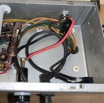
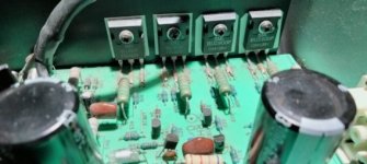
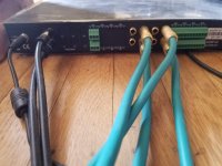
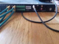
This boiler has an originality: the safety loop is completely autonomous and independent from the rest; it has no external supply.
The safety thermocouple is not directly connected to the gas inlet control, but it is daisy-chained with various safety switches before: overtemperature, overpressure, etc.
The voltage delivered by the thermocouple is tiny: in the 10 to 20mV range, thus any drop along the safety loop would cause problems.
I first thought that the switches were the culprits, but they only drop 1 or 2mV. I then checked the wiring, and discovered significant drops: up to 6~7mV.
The cables themselves cannot be the cause: they are good 1mm² copper, and they have always been in a clean and dry environment.
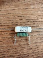
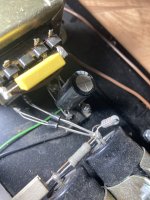
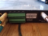
The connectors are Faston type, regular 6.35mm and the smaller size. When I measure the drop between the male spade and the metal of the female receptacle, I only see a negligible, sub-mV drop, thus the only remaining possibility is the contact between the cable and the receptacle. They are professionally crimped, and look in good condition, yet there is a drop of several mV. I have always been taught that properly crimped connections are airtight and very reliable, but it seems that exceptions exist.
The same kind of issue could affect speaker connections for example, and cause tiny sound degradations: I didn't verify it, but I imagine that this contact resistance is non-linear too, and could add some distortion
It is a relatively old (1996) natural gas boiler, but it is from a good maker, good quality, and it is efficient, safe and reliable.
However, restarting it at the end of autumn becomes more and more difficult, and I have decided to investigate.
The problem is that the gas pilot doesn't hold: as soon as I release the starting knob, the flame goes away, even if I keep pushing it for tens of seconds.
This boiler has an originality: the safety loop is completely autonomous and independent from the rest; it has no external supply.
The safety thermocouple is not directly connected to the gas inlet control, but it is daisy-chained with various safety switches before: overtemperature, overpressure, etc.
The voltage delivered by the thermocouple is tiny: in the 10 to 20mV range, thus any drop along the safety loop would cause problems.
I first thought that the switches were the culprits, but they only drop 1 or 2mV. I then checked the wiring, and discovered significant drops: up to 6~7mV.
The cables themselves cannot be the cause: they are good 1mm² copper, and they have always been in a clean and dry environment.
The connectors are Faston type, regular 6.35mm and the smaller size. When I measure the drop between the male spade and the metal of the female receptacle, I only see a negligible, sub-mV drop, thus the only remaining possibility is the contact between the cable and the receptacle. They are professionally crimped, and look in good condition, yet there is a drop of several mV. I have always been taught that properly crimped connections are airtight and very reliable, but it seems that exceptions exist.
The same kind of issue could affect speaker connections for example, and cause tiny sound degradations: I didn't verify it, but I imagine that this contact resistance is non-linear too, and could add some distortion


![PXL_20231109_201928862[1].jpg](/community/data/attachments/1140/1140815-c5e5d4db1d3a747f7220d43549b60109.jpg?hash=xeXU2x06dH)