Hi all,
I know this is the loudspeaker forum but this is directly related to my B&W 802s3 speakers.
I bought a Bass Alignment Filter from a fellow DIYaudio member. He is a very nice guy and I am happy with the parts he sent, the price for them and the promptness of the transaction.
However none of it came with documentation of any sort. I am piecing it together as best I can.
The reason for the post is...
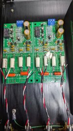
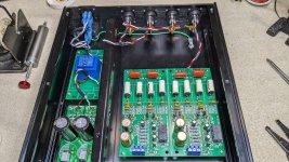
1. Anyone recognize this PCB and have a link to ANY documentation?
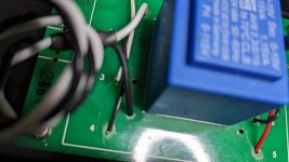
2. The signal lead pads (in and out) on the PCB are not marked for positive or negative. Ground is center. The outside pads are one circular and one square. Any guesses as to which is positive?
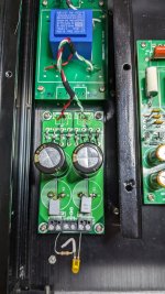
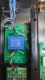
3. The transformer is labeled as dual primary and dual secondary. With secondary as 0-15vac / 0-15vac. However I am getting 22.5vac off both secondaries. Rechecked the jumpers on the primaries to make sure I didn't series the primaries but it doesn't appear so. The rectified DC side is 29.5vdc. Added an LED for some type of load on the DC side but the output of the secondaries didn't change. Kit type PCB's, anything else I can check?
Any help would be appreciated.
My amps are balanced in so the factory BAF I have from B&W doesn't work in this scenario.
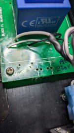
The PCB's came pre-assembled. Several solder pads were filled and I didn't have the confidence in really heating the pads to use a solder sucker or wick to clean them up. So I have what I have...

