Artificial floating ground

Hi All,

This is my first post, so I hope it works ok!

While reading this thread:

much less crazy idea

I noticed the talk of generating floating grounds with big resistors, which reminded of the scheme that Quad used for their 306 amplifer (amongst others, I'm sure). By putting 2 smoothing caps in series, the voltage at their midpoint is roughly equal to half the total supply voltage. To ensure that it remains close to this point, two transistors are used to steer the point to the required voltage. This then forms the signal ground for the whole amplifier.

This arrangement offers DC protection for the loudspeaker - if one of the output devices saturates. the midpoint will be allowed to rise to the appropriate tail, thus avoiding damage to the speaker. The only drawback of this is both capacitors must be rated to the total supply voltage (unlike a conventional split supply, of course)

Hopefully, this might be useful if you happen to have a large mains transformer with a single winding...? Apologies if everyone already knows this!


BTW, click here for the
complete Quad 306 schematic 🙂

Attachments

  • quadpsu.jpg
    quadpsu.jpg
    18.8 KB · Views: 1,427

Need Hornresp help with new push-push slot loaded build

Hi, I'd like to make sure I'm using Hornresp properly for a new build.
It worked very well in predicting the response of a vented PPSL I built a few years ago, but there have been some changes in HR I'm not sure I understand.

Here is a version where the slot has parallel walls. The slot is roughly 19" x 11".
I used the wizard to make an Offset Driver , and put the following into the Horn input fields.
Do the horn segment inputs look correct?

Hornresp staight slot proto1.JPG


Here is a version where the slot is narrow in the back, and wide in the front. With the drivers in about a 90 degree angle like a pict of the sub below.
Slot is about 3" wide in back, and 21" wide in front.
Do the horn segment inputs look right for this version?

Hornresp angle slot proto1.JPG


Pict of angle slot sub.JPG


I'm not asking folks to check my math (areas and length), just trying to make sure i'm going about it correctly.
Thanks !!!

NAD7020e: Avoiding Emitter Resistors 3055/2955

Within this post,

https://www.diyaudio.com/community/threads/hometaxial-2n3055-mj2955.350298/#post-6099879

post #4 claims that emitter resistors can be avoid when replacing the 2N3055/MJ2955 pair in NAD 3020 type amps if at least one is old style hometaxial.

Would selecting any one from each of the two following sets meet this condition, ie. 1. are they all genuine, and 2. are the 2N3055's hometaxial (since apparently there are no hometaxial Motorola MJ2955's)?

Thanks,

Attachments

  • 3055-2024-02-21-10-38-50-675.jpg
    3055-2024-02-21-10-38-50-675.jpg
    225.2 KB · Views: 96
  • 2955-2024-02-21-10-36-48-879.jpg
    2955-2024-02-21-10-36-48-879.jpg
    210.2 KB · Views: 88

NAD 7020e Biasing Mistake - Which components to check after the 2N3055 and MJ2955?

Hello. I recapped a NAD 7020e. It worked after the recap. I went to set the bias when the meter leads got pulled and shorted out. The 2N3055 (Q415) and MJ2955 (Q417) got toasted and have been replaced. In looking for further damage, would there likely be more components beyond Q411, Q413, R453, R455, R457, C431, C433, C435, C437, and C439?

Thanks,

Attachments

  • NAD7020e-crop.png
    NAD7020e-crop.png
    583.6 KB · Views: 111

ƑƠɭįƠ is a simplistic, yet automatic outer foil tester for capacitors

ƑƠɭįƠ is a simplistic, yet automatic outer foil tester for capacitors

Following some discussions about the subject, Outer foil cap measurement with Hantek 6022BE
Cap Foil Side Tester,
here is a small project based on the principles outlined here: Outer foil cap measurement with Hantek 6022BE

The process is rendered completely automatic: one just has to insert the cap to identify into the instrument, and a LED instantly indicates the foil side:

804263d1577123994-simplistic-automatic-outer-foil-tester-capacitors-folio1-jpg


No more need for manipulations, comparisons or measurements.

The principle of operation is to send two antiphase waveforms to the CUT, and detect the polarity of the signal electrostatically leaked to the outside with a synchronous detector.

804264d1577123994-simplistic-automatic-outer-foil-tester-capacitors-folio0-png


A single IC performs all the signal processing, and two transistor-based buffers handle the higher currents needed for large value caps (the instrument is designed for up to 4.7µF, but still gives usable indications with 10µF).
For fun and challenge, I built the whole thing into a small box of ear-plugs ("boules Quiès"):

804265d1577123994-simplistic-automatic-outer-foil-tester-capacitors-folio2-jpg


The box is tiny, made of thin and soft PP (thus non-conducting, providing no shielding), and barely contains the circuit and 9V battery.
The power push-button is located underside: you just need to push on the box to operate the tester:

804266d1577123994-simplistic-automatic-outer-foil-tester-capacitors-folio3-jpg


For large capacitors, the tester is equipped with an aluminum bracket and a phosphor-bronze strap, helped by an elastic band:

804267d1577123994-simplistic-automatic-outer-foil-tester-capacitors-folio4-jpg


804268d1577123994-simplistic-automatic-outer-foil-tester-capacitors-folio5-jpg


The smaller caps are handled thanks to a phosphor-bronze spring:

804269d1577123994-simplistic-automatic-outer-foil-tester-capacitors-folio6-jpg


The construction is not especially tidy, but it works well:

804270d1577123994-simplistic-automatic-outer-foil-tester-capacitors-folio7-jpg


804271d1577123994-simplistic-automatic-outer-foil-tester-capacitors-folio8-jpg


The usefulness of such a gadget might seem questionable, but in fact a surprising proportion of capacitors are mismarked: more than 10%.
An example is the small yellow-block shown above: it is from the Philips/MBLE/RTC etc. group, not some dodgy Asian manufacturer

Attachments

  • Folio1.jpg
    Folio1.jpg
    228.1 KB · Views: 2,967
  • Folio0.png
    Folio0.png
    29.2 KB · Views: 2,876
  • Folio2.jpg
    Folio2.jpg
    240.9 KB · Views: 2,873
  • Folio3.jpg
    Folio3.jpg
    192.6 KB · Views: 2,803
  • Folio4.jpg
    Folio4.jpg
    213.4 KB · Views: 2,795
  • Folio5.jpg
    Folio5.jpg
    208 KB · Views: 2,759
  • Folio6.jpg
    Folio6.jpg
    180.7 KB · Views: 2,840
  • Folio7.jpg
    Folio7.jpg
    263 KB · Views: 2,836
  • Folio8.jpg
    Folio8.jpg
    314.5 KB · Views: 2,664

Hum identification

Hi,

I have a Fender-style preamp with one 12ax7.
It gives me hum which seems to be related to the power supply. It sounds like this: Login to view embedded media (normalized).
It's not unbearably loud, I would say it's liveable, but it still is really annoying.

The thing is when I disconnect it from the mains, I get a few seconds of absolutely beautifully hum-free (while there is a charge in the capacitors) guitar sounds.

I believe the preamp circuit doesn't have ground loops (for every ground point in the circuit I have a separate track going to one single point which is connected to the power supply's 0V). The power supply I use is https://www.aliexpress.us/item/1005005909458258.html (seems to be pretty solid).

I have tried a huge 8 Henry choke on the 300V output of the power supply. I have tried balancing the output signal with the transformer (hoping the balanced result will cancel this hum), but nothing seems to help, the hum is still there. I have even dangerously tried to temporarily disconnect the mains earth connection (just to quickly check) and the noise gets much worse when I do that.

I would prepare myself for living with it if not for these beautiful few seconds of beautiful quietness when I disconnect it from the mains...

Could someone help identifying the problem (and finding the solution)?

Thanks.

Requesting help building ASUSA 100 watt, 6146 tube mono amps

About a month ago I made a deal to buy a pair of partially assembled 100 watt mono amps from ASUSA. The amps aren’t yet in my possession but are paid for and I should have them this Sunday or Monday - I just need to go pick ‘em up and will post more pictures of these when I have ‘em.
Apparently these use a couple of 6146 output tubes, driven to 100 watts. These amps may or not have been one of their kits but possibly some stock being assembled shortly before their closure (?); I haven’t been able to find any info on these in this 100 watt version and don’t have a schematic.

I’ll be needing help building these up.. I’d like to stay with a 6146 build to try it out. I know that in the ‘50s, Altec made some theater amps using the 6146 tubes so maybe that circuit could be an option.

Pictures I have as of today; more to come when they’re here:

10D61A2B-CF77-4D1A-97D8-1EF7060DF64D.jpeg
88B9642D-68B7-4CCD-B4DB-FCE13FD5FE0D.jpeg
473666BE-64A3-4A00-9F45-F9A1620E0C7F.jpeg
8612C52F-CC22-40DB-9C89-599E7A99D03B.jpeg

Mini speaker, Passive Radiators, and the ND65 vs ND91

Speaker Parts 1.png
Speaker Parts 3.png
Speaker Parts 2.png

This is my first time building.
I got together some parts and ideas from advice in a post I made earlier and some builds I've seen. I've seen quite a few videos and builds using the ND65 and ND91 speakers and just today I saw this as well: https://www.parts-express.com/Passive-Aggressive-Mini-Speaker-Kit-Pair-300-7148?quantity=1 I remember seeing they are based on the Aurasound NS or something like that.

My goal is to try and build a decent small Bluetooth speaker to plug in my Qudelix 5k Bluetooth DAC/DSP equalizer. I'm still trying to decide if I want to go with the ND65 or the ND91, but im fairly dead set on doing one of the two, now. I have become aware that if I go with the ND91 I will have to build a much bigger enclosure, and my goal is to make this as small as reasonably possible. But I also want hz to go below 100, and as low as I can get it. I can tune it with the passive radiators and the Qudelix 5K's DSP, but I also need to make sure my enclosure is big enough. I've tried using https://speakerboxlite.com/subwoofer-box-calculator/tab-graphs and I think I have an idea of what I want to do. But I'm worried I did something wrong. And I think I might need to add an LPAD to bring the sensitivity of the tweeter down closer to ND65/91... but I also have the Equalizer, so will I need it? Can't I just mass-lower those frequencies? It's more expensive, but should I do a 3rd order crossover? I've also been thinking of getting the TPA3116 50w amp instead,.. but that seemed like a bit much.

threshold s 500 update

hello all,im new here and was wondering what i should do. i recently got a threshold s 500 its the silver 1. i dont know if its series 2 or not.i read on an avs forum that said it could be modified to pure class a @160 watts??? wonder if thats true, im going to try to make this my last amp purchase,does anyone now the best way to make this amp sound its absolute best as far as mods/upgrades. thanx ...janx

Mains transformer safety Q

Hi,

I'm currently window shopping parts for for an upcoming 300B SET project. I already have the tubes, output transformers and interstage transformers but no suitable mains transformer.
I recently used some transformers from the (seemingly rather unknown) Italian brand Piemme in a project and I'm quite happy with the price/quality ratio of their iron.
They have a few mains transformers that would suit my needs and this one in particular would be perfect, with its high-ish voltage bias winding, high current heater winding for the damper diodes I intend to use as rectifiers (in a hybrid bridge) and a HV winding with several taps that would let me to adjust the B+:
traf.JPG


What bothers me is the CT on the HT winding. Using this transformer with a FWCT rectifier wouldn't produce anywhere near the voltages I need (~400VDC) but in theory it would be simple enough to just ignore the CT and use the full winding with a hybrid Graetz rectifier bridge.
The question is: Would in be safe? Not grounding the CT must put more strain on the inter-winding insulation, am I right?
I guess the right thing to do is to ask the manufacturer, but I'd like to hear any opinions the good people here might have on this subject first.
  • Like
Reactions: TonyTecson

Decware Betsy and Edge Software

How important is the use of Tolvan's Edge Software?
Take Decware Betsy OB speakers as an example. When Edge is given the dimensions for the Betsy you get an enormous off the chart peak @ 500 Hz (approx. +15dB),
and @ 60 Hz the output is -4dB which is a difference of 11dB.
The Betsy speakers are supposed to sound quite good despite the rather horrible response indicated by the Edge software, so what is going on here?
- Either I'm missing something (which of course is quite possible), or the Edge's response curves aren't really that important.

PA DSP Options Mixer Vs DBX PA2

I am keen to understand more about a decent option of DSP for a large venue. The sound engineer for the venue states that the QSC TouchMix 30 Pro has DSP and the specifications on the website does mention "room wizard to simplify equalization tasks." Does this DSP have enough taps and how would it compare to a DSP such as the DBX or other similar type DSP's such as the Silica?

Apparenlty the QSC even has the option to put a mic and play pink noise to get a measurement. If I am not mistaken the PA2 also has this option which is automatic if I am not mistaken? Any input would be helpful.

Quick question about 2x9V transformer

Long story short: Can all transformers that have two equal secondaries be connected in parallel? Like these?

Long story...:
I want to build another Raspberry Pi Streamer, and use the "P05" linear power supply from ESP (I have an extra one).

According to the instructions, I should use a transformer with a single 9V output.

Those are hard to find... well, until I realized I can use a 2x9V transformer, and simply connect the two secondaries in parallel.

Some data sheets (like from Triad) specify the serial and parallel specs, but others don't. Does that mean I shouldn't "parallel" the secondaries??

I am talking about toroidal transformers from Vigortronix; here is the datasheet:
https://www.farnell.com/datasheets/3964075.pdf

I am thinking to get part no. VTX-146-030-209, which, with secondaries connected in parallel, should give me 1 x 9V @ 3.34A.

Please let me know if I got this right 🙂

For Sale NewClassD, clock NeutronStar2, 24.576MHz (Europe ship.)

Hello,
I sell this NeutronStar2 clock from NewClassD.
Output frequency => 24.576MHz

Perfect item to use on a DAC / streamer etc…
In my case, this NS2 replaced the Crytek on a digital interface Singxer SU-1. Given that I resample all streams to 24/192, this NS2 was perfect.

I powered it using a transformer & a linear PS (MPaudio HPULN).

Honnetly, I never checked its power consumption… but given that the linear reg module ran "cold", it's for sure well below 1A.

I still have the SMPS from NewClassD (15VDC output), if interested just ask.
But I prefered to use a linear PS to get a better SQ.

Please note that the typical voltage of the PS is 15VDC, but it works perfectly down to 12VDC like I did.
If I remember, 12VDC must be considered as the bottom of the PS range (10VDC and below => too low, it did not starts, as far I can remember)

Its dimensions : 14cm long / 4.5cm wide / 2.5cm high
Output connector is SMB (I provide it, see photo) ; or use the pins on the right of the SMB connector (didn't try that)

Price : 100Eur + ship cost (ship to Europe only, tracking ship No)
Payment : PayPal

I'm living in Paris suburb (FR), if you're around we can meet for free shipping 🙂
Feel free to ask question

Rgds

Attachments

  • 20230605_041344.jpg
    20230605_041344.jpg
    466.7 KB · Views: 149

need help with upgrading capacitors in a tube amp

The audio bugs are getting back to me. I want to upgrade the caps in a tube amp: 0.10uF 600V film capacitors.

I did a bit of homework and found this: https://forum.bottlehead.com/index.php?topic=11668.0
quote, "I bought a pair of Audiocap PPT Theta 0.10uF 600V Film/Foil Capacitors for about $15 USD", by Natural Sound. that was a post from 2019.

but when I look it up. it is more than $70 now for a pair on part express. ouch
https://www.parts-express.com/Audio...lVpu8zb7CyDHJJ21JhQv_excdUjrmcT0aAiEPEALw_wcB


any suggestions? any other caps that will work as well as Audiocap?

I found this one: Jantzen Audio 0.10uF 1200V Z-Superior Capacitor.
https://www.parts-express.com/Jantz...ztNmDwHO8qpDNragLEBeapt2Q95TWts8aAvPxEALw_wcB


or this one,
https://www.digikey.com/en/products/detail/nichicon/PHC1604200KN/13662904?utm_adgroup=General&utm_source=google&utm_medium=cpc&utm_campaign=PMax Shopping_Product_Zombie SKUs&utm_term=&utm_content=General&utm_id=go_cmp-17815035045_adg-_ad-__dev-c_ext-_prd-13662904_sig-Cj0KCQjwhtWvBhD9ARIsAOP0GojGhwOGG7w3brDbw14rqoqIV5aPXe6X-mP1Sps8MkFSS6YhQgA-xfkaAgTFEALw_wcB&gad_source=1&gclid=Cj0KCQjwhtWvBhD9ARIsAOP0GojGhwOGG7w3brDbw14rqoqIV5aPXe6X-mP1Sps8MkFSS6YhQgA-xfkaAgTFEALw_wcB


mundorf for $15:
https://www.madisoundspeakerstore.c...yZXZwMOTTZ8ODXOf1UC0mdWJKpacBnzoaAiDBEALw_wcB


Thank you in advance. Have a great weekend!

Kenwood DP-1000 laser pickup problem

Hi all,
I am new here. I picked up a Kenwood DP-1000 CD player which had a few problems that I've already addressed (namely, 2 shorted electrolytic capacitors in DAC section, and CD tray motor belt replaced, and gear lubrication). There is one more issue that it has that I am trying to resolve.

Issue:
Sometimes (not always!) when I attempt to play a CD, the laser pickup seems to "spazz out" for want of a better term and moves too far toward the front of the unit.
When it happens, the gears responsible for moving the laser module are fully torqued and get stuck. If I press Play again, the motor backs off and seems to reset.

It happens maybe 50% of the time when I try and play a CD. I noticed that it will also happen about 50% of the time when I attempt to pause the CD. Sometimes it will pause gracefully and the laser sits in place, and other times it does the "spazz out". I've recorded a couple of short videos which hopefully illustrate the issue. If anyone has any idea on what might be causing this issue, I would be most grateful to get your advice.

This shows how the motor and gear assembly gets stuck during playback:
Login to view embedded media
This shows how the motor resets itself from a stuck position when I press 'Play' again:
Login to view embedded media

MSB Technology vs. McIntosh

I'm looking to upgrade the digital source of my system. My current system is listed as follows:

Streamer: NuPrime Omnia Stream mini DAC: Soundstream DTA-1 (Yes, it's car audio device)
Integrated amplifier: ADS atelier A2
Speakers: ADS L1590/2

Nowadays, the DAC has a problem of unbalancing between left and right channels. I surfed the internet and found two interesting DACs for sale near me. They are
1) MSB DAC link
2) McIntosh MB20

The MSB is older than McIntosh. It's pure DAC though, and was launched in 1999 with a number of positive reviews. The McIntosh was recently introduced a few years ago. It's not a pure DAC but equipped with a Bluetooth receiver. IMHO, this McIntosh Bluetooth+DAC might be categorized as the lowest model of McIntosh gear. However, the price of the McIntosh is twice higher than the old MSB.

I'd like to ask for opinions, which one will you choose and why?

Martin Logan Depth I drivers vibrating when turned on without music

Hi all, I am having an issue with my Martin Logan Depth I subwoofer. Let's start from the beginning. I found out that my sub was damaged before covid era. Took time to look inside the sub and found out lots of corrosions on the boards..some of the connectors shows signs of burnt ! Called ML back then and was told no parts available during covid due to shortages of parts. Fast foward to today. ML finally got me the power supply, amplifier and the top assembly boards totaling about $700! The good news is the sub is back in action. But the bad news is sub is acting wierd......meaning all 3 woofers would sometimes vibrating without any signal at all. The vibration stops when I put it in standby mode. I also think that when I play the music, the woofers is vibrating even there are no big bass going on. I also notice continuous thumping sound coming from inside the cabinet. The woofers also making continuous clicking sound when the issue arises. When I switch to auto mode, the sub is having trouble recognizing the signal from the source ( the led light keep switching from orange to green back to orange...) I noticed the outer wrapping of the transformer is slightly blackened. Is the transformer bad too?? The problem is intermittent...sometimes I turn it off and it goes away but may come back.. So to wrap it up. Do I have 3 bad woofers? Should I try replacing the transformer and also all the connectors and hopefully fix the issues? I don't have any electrical or audio engineering background. Just swap and plug type of guy. Please help!!

Repurposing a Classic Cassette Deck as a Digital Audio Streamer

I thought that I might share my progress on my repurposed 70's HiFi as a digital Music Streamer project as it is now beginning to gain some momentum.

I have chosen to use my existing RPi3 which I had along with an Allo Digi One hat and a recently acquired 7" touch screen.
After a bit of a tussle I have it running Picoreplayer allowing access to Qobuz and locally stored music files in the Micro SD card. So, all good so far.

Here is a picture of the donor chassis I have a choice of a 1978 JVC or a 1975 Sony Cassette deck, both ebay 'not working' purchases, (Well actually i have since fixed the JVC, loose flywheel issue) so it looks like the Sony is going to be the selected donor. It is also the best made, very solid indeed.

FGVQ6432.JPG


The plan is to remove the cassette mech and put the RPi 7" display behind the front facia in its place. I can see that I am going to need a bigger hole than just that left by the cassette door opening. Careful metal working may be required here!

IMG_4434.JPG


IMG_4436.JPG


The usual RPi/Allo Digi guts behind the display.

The plan is to use this as a SPDIF digital out only device with the bnc output going to the back panel and the RCA digital out feeding the VU meters. I have ordered a cheap DAC to provide a line level signal to drive the VU meters and a mini QWERTY keyboard to hack to provide momentary push button inputs to the RPi for functions like, FF/Play/Stop/RW/Pause etc. The plan is to fit new microswitches to the cassette piano keys so that they can operate the Picoreplayer functions of the same description via the hacked USB keyboard.

However I am a 'bit at a loss' to know what to do with the 'Record Level' and 'Line level' Knobs and the 4 No. 'toggle switches' Any ideas?

I can use the keyboard hack to access up/down/left/right in the picore player, but the knobs have potentiometers attached, as you would expect for 70's electronics, I could modify them to operate a couple of micro switches for left/right/up/down 'etch-a-sketch' style, but its going to be quite a task and I really not sure what to do with them that might be worth while even then?

I have tried a USB mouse, but I am not able to get a reaction from Picore to this device. Do you know of any cheap USB devices that might allow me to tap into the rotary action of the knobs that i can use via the Picore player?

The touch screen and phone/tablet interface can do everything but, it would be nice to give most of the front controls a use, don't you think?

I would appreciate any ideas you might have.

Last edited: 13 minutes ago

For Sale AMB γ2 DAC

SOLD!!!

I am putting my AMB γ2 DAC up for sale. It's built with the γ1 "full" configuration without the ASRC chip on the γ2 extension board. For more information, please visit https://www.amb.org/audio/gamma2/ I have been enjoying this DAC for quite a while but it was time to upgrade. Hopefully someone else could make good use of it. Payment is with paypal or cash. I can send it anywhere within the 48 continental states for an additional 10USD. Local pickup in Princeton, NJ.

Price: 100USD
DSC04717.png

Attachments

  • DSC04720.png
    DSC04720.png
    156.9 KB · Views: 111
  • DSC04723.png
    DSC04723.png
    324.4 KB · Views: 109
  • DSC04726.png
    DSC04726.png
    351.9 KB · Views: 114

NIB (x8) Oaktron by Misco 127-MR08-01 sealed 4.5" 8Ohm drivers

For sale are eight new in box Oaktron by Misco 127-MR08-01 sealed 4.5" 8Ohm drivers. Fantastic speaker unfortunately my project changed directions and these can be yours at a discount.

I would prefer to sel the lot for $450 plus shipping.

Or

$55 per driver plus shipping.

Attachments

  • PXL_20230626_184416707.jpg
    PXL_20230626_184416707.jpg
    421.8 KB · Views: 89

Panel Meter Source

I want to add a couple of small meters 1-100 mA and 0-10(ish)VDC to the front of my soon to be built 300B amps. There is a large amount of blank green surface I want to create some interest within as well as providing some information.
I have some of those inexpensive meters like below but I'd like something bit more classy and better quality. The advantage of this type is if it fails, it is easily replaced. The vintage stuff, like I've used in the past (second pic), has gotten stupidly expensive and hard to source matched pairs.
Thanks for any leads/thoughts.61lpdTj6oXS._SX522_.jpg20231031_122234.jpg

A question to members selling products

Hi all,

First off please excuse any bad wording as english is not my native language.

That's a rethorical question really but I'm curious when I see some people selling their projects. Personnally I'm not confident enough in my electrical knowledge to think about selling anything I design or build especially regarding all the possible hazards; Sell enough things and there will inevitably be problems. My question is, do people selling projects get some sort of insurance against these hazards? I doubt any insurance company would offer coverage of an electrical product that isn't UL/CSA certified, and the process of getting an underwriters' certification can cost in the tens of grands I think, so out of reach of most enthusiasts here. Same goes for personnal liability insurance, I don't think these would cover damage resulting from an non-UL listed appliance. I also do not believe any form of liability waver in the form of a disclaimer can stand in a court of law. I recently learned that at least in Canada, even for used item you can still be held responsible if that old toaster you sold for 2$ burns down the buyer's house. Makes you think twice about selling anything with a wall plug...

Looking forward to hear from experienced sellers !
- Joris

For Sale UGS Muse full set + option 1 & 2

-- Sold --

Hi,

Due to changed plans, i am selling a full set of the UGS Muse preamp PCBs, plus option 1 and option 2 (see the screenshot from the group buy sheet below).

See information here:
https://www.homecinema-fr.com/forum/diy-amplification/ugs-muse-edition-t30058092.html

And the group buy thread here:
https://www.diyaudio.com/community/threads/ugs-muse-preamp-gb.277355/

I am selling for 135 EUR plus shipping, this was the same price i paid for them.
Prefearably only in EU.


1706729143897.png

Attachments

  • IMG_1700.JPEG
    IMG_1700.JPEG
    703.6 KB · Views: 139
  • IMG_1707.JPEG
    IMG_1707.JPEG
    835.5 KB · Views: 143
  • IMG_1706.JPEG
    IMG_1706.JPEG
    938.4 KB · Views: 128
  • IMG_1705.JPEG
    IMG_1705.JPEG
    495.3 KB · Views: 129
  • IMG_1704.JPEG
    IMG_1704.JPEG
    889.5 KB · Views: 127
  • IMG_1703.JPEG
    IMG_1703.JPEG
    715.5 KB · Views: 126
  • IMG_1702.JPEG
    IMG_1702.JPEG
    562.2 KB · Views: 113
  • IMG_1701.JPEG
    IMG_1701.JPEG
    560.6 KB · Views: 137

Accuphase E210 modified version

Many years ago, in fact, I had a gold voice E210 E305 series PCB circuit which imitated the board.
I also made some test boards. The result is: if DIY's golden voice, the performance is not as good as the original machine.
Even the LM3886 estimate is not comparable. So I sent the PCB made. Then? There is no more below.
Especially around 2006, the music fax X-A50 is also being imitated and DIY improved at the same time.
Comparisons show that the X-A50, the later DIY version of MX50X2, is much better than the directly engraved Golden Voice E-210 in all aspects.
So later, the similar circuit in Jin's voice did not continue DIY anymore.
In the following process, I also found some reasons for the problems.
Firstly, the circuit of the golden voice is fully symmetrical. This circuit is symmetrical in theory, but in practice, the inconsistency of the components makes it possible to apply it in practice.
The distortion of full symmetric circuit is greater than that of single-ended amplifier circuit.
For example, L series L12-2 L20.5 and music fax X-A50 distortion, is better than the golden voice, Malanz, similar structure.
Later, after a long period of research, in fact, that is to say, when you have time to study it by the way. It is found that the imitation of golden voice circuit should be made directly according to the original factory.
Not ideal, after all, DIY components are different from the original factory.
Some DIY imitations use the same type of components as the original factory, but the brand is different.
More is the use of alternative components. That is to say, no matter the model, brand, or even the parameters are completely different from the components of the factory.
But the circuit parameters are the same as those of the factory.
There are even some field effect transistors, which are directly changed into triodes, but the circuit structure is exactly the same.
This is a messy approach, but many circuits like Golden Voice use JFET MOSFET, and the model is hardly directly available.
So many DIY can't do anything, only to make a messy change, as long as the final success.
In fact, I do not object to the change, because DIY is not a manufacturer, it can not have exactly the same components. But if we make a random change, only God knows the good and bad.
This kind of DIY is in fact a universal imitation of famous machines, not limited to the golden voice. Other imitation machines are also included. This is also inevitable.
Because many components are not available, and even many of them are out of production. And some manufacturers have changed the model of components. For example, the power transistors of music fax are all MF letters.
MF stands for music fax, but as everyone knows, music fax does not produce transistors. The most important thing is to print your own trademark. We can only guess what model it is.
The end result is. Amplifiers from most imitation manufacturers. The actual performance is quite different from that of the manufacturer.
In my opinion, imitation does not need to copy the parameters of the original factory. At most, if the circuit structure remains unchanged, the application of each transistor can be appropriately based on the needs of the circuit type.
Make some adjustments.
Finally, the most important thing is to measure the amplifier. The measured data are compared with the parameters of the original plant, and then improved to achieve the same results as the original plant. It may even exceed the performance of the original machine.
This is a more practical imitation.
Without changing the circuit structure principle of the manufacturer, it is my personal imitation idea to bring the circuit performance of this structure into a better state.
Most DIYERs do not pursue performance metrics very much, and of course there may be no such condition. After all, a tester AP2722 costs hundreds of thousands of yuan.
But we can try to make it in this direction.
Here I start with the original version. Direct copy of the golden voice E210 PCB. I've done a lot before. They're all given away.

Attachments

  • 20032141146315904.gif
    20032141146315904.gif
    76.9 KB · Views: 2,698
  • 200321411414866231.jpg
    200321411414866231.jpg
    314.3 KB · Views: 2,011
  • 200321411452588507.jpg
    200321411452588507.jpg
    758.5 KB · Views: 2,376
  • 200321411455434768.jpg
    200321411455434768.jpg
    424.6 KB · Views: 1,786
  • E210.jpg
    E210.jpg
    303.5 KB · Views: 2,078

In-wall Overnight Sensations left/right surrounds

Hey folks,

Just starting out on my diy speaker foray and am aiming for a 7.1 home theater build eventually.

I'm intending to do Overnight Sensations LCR, and probably MTM all round. But the problem is while my rear surrounds I can happily wall mount in the corners of my room the left and rights will need to be in-wall.

Has anyone made an in-wall OS build?

Or would anyone be able to recommend a commercial in-wall option that might have reasonable voice matching to the OS MTM I'll have for the other speakers?

Thanks
--
Ben

Mini MEH

Over the past weekend at a Hackathon I have designed and printed a small MEH. I used ATH to generate the horn then simmed the HF and measured it to compare. I then also decided to add some midrange 2" drivers to see how it would turn out.

I am so happy with how it turned out for 1 weekends worth of work and not really any simming haha.

On the midrange measurements there is a big dip at around 1350hz the length of the horn is 120mm which would be half a wavelength from inside the compression driver to the horn mouth. Do you think that could cause the big dip at 1350hz then boost (1/3rd wavelength) at just below 2000hz?

Rear.jpg

The drivers I used were ones that were already here, it was two Faital Pro 2FE35 and a Lavoce DF10.172k which is way overpowered for the midrange haha. The rear chambers were made out of tape and hot glue.

This is the response after processing:

Response.jpeg


This is the unprocessed measurements:

Mid and HF.png


The following are the polar plots (only up to 40 degrees each way)

Normalised Horisontal Polar.png


Normalised Vertical Polar.png


Some pictures of the measuring process:

Measuring.jpg


Marked for Polar.jpg

For Sale Aleph J complete. 5U chassis housing twin sub chassis, Traverse City, Michigan

I recently rehoused my original Aleph J into the 5U chassis, thinking I would take it with me when I move but I cannot take as much as I once thought.

I built it in its orginal form some time back, using DIYaudio store kit parts, scrupulously matched transistors, oversized Antek transformer, original Toshiba JFETs, Russian PIO input caps, military silver plated wire, and a propensity for barrier strips for solid joints assembly and disassembly. However, the damn thing is HEAVY! Note the rear handle/guards and front rack handles for rolling it on its back before picking it up! I do not want to ship this across the country (I once thought I'd palletize it for my move ;-). If you want me to ship it to you at purchase consider it parts as I have had very bad luck with cross county shipping. I would gladly give it over to UPS for pack and ship, I've no idea though how (very) expensive that would be. My price reflects less than a parts cost and does not include shipping.

I live in Traverse City, Michigan, USA 49685.

I built it for keeps but now I cannot ;-(. $600

Attachments

  • IMG_6086.jpeg
    IMG_6086.jpeg
    590 KB · Views: 233
  • IMG_6085.jpeg
    IMG_6085.jpeg
    551.3 KB · Views: 195
  • aleph J front.jpg
    aleph J front.jpg
    480.5 KB · Views: 214
  • internals left channel.jpg
    internals left channel.jpg
    508.5 KB · Views: 217
  • right ch.jpg
    right ch.jpg
    261 KB · Views: 222
  • high up RR.jpg
    high up RR.jpg
    436.1 KB · Views: 229
  • IMG_6087.jpeg
    IMG_6087.jpeg
    600.5 KB · Views: 230

BA-3 Preamp for sale

It's time. I must sell everything. Today I am listing the BA-3 Pre. Like mosts of you I build for myself and have done my level best to create something worth keeping "forever". Oh well, I must move to another country and cannot keep almost anything. Here is a chance to hear a nice one without the expense of time.

I do like that the "warmth" can be adjusted but set it to "neutral" in the end. Funny again, how things go. If you think it pretty, cool, I am told my "dancer" has a strange hairdo, it is taken from an Art Deco figurine. Art is so subjective 🙂. $400. I can ship anywhere and I will pack it well but I cannot guarantee it gets through the gorillas to you in good condition. Think of it as parts.

Attachments

  • BA3 front dim light.jpg
    BA3 front dim light.jpg
    304.3 KB · Views: 155
  • BA3 pre dancer close.jpg
    BA3 pre dancer close.jpg
    385.8 KB · Views: 147
  • tempImageo9Gm6R.gif
    tempImageo9Gm6R.gif
    700.8 KB · Views: 168
  • BA3 build.jpg
    BA3 build.jpg
    421.1 KB · Views: 170
  • IMG_0923.JPG
    IMG_0923.JPG
    417.6 KB · Views: 175
  • cold front.jpg
    cold front.jpg
    811.9 KB · Views: 162
  • cold light rr.jpg
    cold light rr.jpg
    775 KB · Views: 164
  • Like
Reactions: Gill.T

Goldmund Studietto JVC motor info wanted

Hi all
I have inherited a Goldmund Studietto in VERY poor shape. It was completely destroyed during shipping after shipper didn't pack it well. I can restore it somewhat, forget about cosmetics and some parts will have to be replaced with home-brewed variety ))) My main concern was the motor. It is a JVC direct drive unit, same as used in QL-A75. I soldered back some wires, and improvised switch connections (since all three switches were destroyed as well). Great news is that it's working. It starts strong and within 2 seconds quartz lock LED lights-up. But there's something screwy with the ON-OFF switch: the normal state is actually ON, so when I put jumpers in the OFF position, motor stops, but my bench power supply still shows a current draw of 60 mA. I remember way back when I was rich and famous and had a Studio, it liked it's power supply constantly on, and it was slightly warm. So I wonder if this is a factory design to keep electronics warm? Or some caps are leaking on the motor control board? Or? Ant advice appreciated, thank you.

Attachments

  • IMG_7675.jpg
    IMG_7675.jpg
    406.6 KB · Views: 158

Connecting two microphones

Hello all,

I have a peculiar project that I need some insight please.

I own a T10 Shure wireless headset microphone - its cable ends up to a 4-pin (female) plug (maybe the cylinder frame around also acts as a "pin").
I want to connect this microphone to another microphone that I own. The latter is a typical "cone" microphone that when I unscrew the top part, I can see the microphone as well as only two cables connected to it.
My project is the connection of the T10 Shure to the cone microphone but:
1) I don't know which 2 pins of the T10 Shure to connect with the 2 cables of the cone microphone
2) I don't know if this project makes sense anyway in terms of quality of sound achieved

Any input more than welcomed!

Thanks in advance,
Al

Pioneer GM-DX874 cuts out

Installed this amp with 2 -12" kicker subs and found that it will cut out on certain songs when the lower frequency hits. Thought it was needing more power so hooked up a 3 farad capacitor and still having the issue. I have the speakers bridged and have messed with both the frequency and the gain but get the same results. It doesn't cut out when turning down the gain but then I lose the desired bass. Something not hooked up right or is the amp possibly bad?

SIT-Preamp

Behind this schematics stands an idea to try using SIT transistors with triode-like output characteristics for simple preamp design. The common source stage based on KP926A Russian SIT transistor is used for amplification (nearly 20 dB) at 100V power supply voltage and 175mA quiescent current, class A operation. Unfortunately, KP926A has 1600pF of Ciss (instead of this transistor much better would be SONY 2SK60 which have Ciss = 190pF). To handle the 1600pF of input capacitance of KP926A one needs a buffer stage, which I decided to make like well known j-fet follower with 25mA quiescent current and plus-minus 15V supply voltages. One needs a decent j-fets for such a buffer, like for instance CP650. In my case I used Russian KP601A, which is close to CP650. The Ciss for KP601A is 6pF. Before this buffer a simple volume control based on 10kOhm ALPS resistor stands more than comfortably. In fact, I used a voltage divider constituted by 7,8kOhm low-noise constant resistor and the variable part of ALPS below it. Capacitors used include Elna Cerafine, Mundorf polypropylene etc. This schematics has no NFB, its output resistance (measured by immitance meter) is 200 Ohms. I compared it sonically with the good Parasound JC2, which has only 60 Ohms output resistance. Power amp was 50W version of Pass Zen9, Shanling CD T-1500 player, speakers are Paradigm Studio 100 v4, cables Stereovox (speaker), Nordost (interconnects), power is provided by PS Audio Power Plant Premier. I can say that I love my Parasound JC2 very much, but in this comparison SIT-preamp sounded more musical. It gave more detailed and pleasant low-mids and the bottom end. At the beginning I thought that SIT-preamp has lower output resistance than JC2, but it is not. So, I do not know what a magic stands behind it. Speaking about transparency of highs the two preamps are very close, in some cases maybe JC2 is a bit better (difference on the level of tiny cabling effects), but JC2 is connected to XLR outs of Shanling (known of being better) on contrary to RCA outs for SIT-preamp. I would be grateful for help in understanding what a “devil” is behind this SIT-sound.

SIT-preamp.jpg

3EF with floating pre-driver vs Wolverine 3EF

To use a low cost low noise high Hfe bc550C/560C as pre-drivers, I float them with a bootstraped supply. The result compared to Wolverine 3EF with single pair outputs is higher impedance and lower distortion.
These are measured with 1Mohm source 20ua 1khz input vs 22ua for Wolverine.
The biases are adjusted for minimum distortion 0.068% vs 0.31%.
3EF.JPG

fliating 3ef.JPGwolv 3EF.JPG

Attachments

  • 3EF WOLV.JPG
    3EF WOLV.JPG
    28.2 KB · Views: 101

Kicker ZX1000.1

Good afternoon everyone, on this occasion I am urging you to repair this Kicker brand amplifier model ZX1000.1 REV 2.1. At the beginning, damage was found in the power supply, it has already been recovered and in the output stage there is an auxiliary supply that was damaged, the 2 htp18n06g were replaced and the 1n4002 diode is already oscillating, but now I have stopped at the driver card, I already managed to get it to turn on and stay on, I don't have any pulses in the output fets, I mention that I have the fets outside the board since if I leave them inside they won't stay on, greetings

Attachments

  • 17103582126341382866155772797705.jpg
    17103582126341382866155772797705.jpg
    910.8 KB · Views: 212
  • 17103582362419157792094760446307.jpg
    17103582362419157792094760446307.jpg
    709.8 KB · Views: 150
  • 17103582636123192341235916483158.jpg
    17103582636123192341235916483158.jpg
    824.7 KB · Views: 172

Comments on Build Guides?

I'm using the F5 build guide to put together an F5 v3 amp and I can see that 12 comments have been posted, but I'm not able to see the comments themselves. I have a faint memory that some of these comments were very useful, and I found them useful when building the Amp Camp amp. Am I doing something wrong? I tried different browsers and am signed into my diyaudio store account. (Sorry if this isn't the right forum for this question).

Envisioning a 2.5 MMTMM thoughts?

So a fellow member of an astrophotography club I’m in shares my passion for hifi but not the time or ability to DIY and in some deep conversations, I’ve convinced him that we can outdo his Sonus Faber Strads for around 1/10th the cost. He’s paying for the material and absorbing the airfare for our summer photo trip to Utah as a gratuitous bonus for design and labor!….not a bad deal for him! Lol

Promises fulfilled, ……..we’ll make his floor plan more open and his wife happier by replacing the obnoxiously fat body Strads with a tall, slim enclosure only 6.5” wide and 18” deep. Folks here who know me also know I firmly believe that narrow baffles are the ultimate in stereo imaging…..once you’ve done an A/B comparison where the bass response is fairly similar, I don’t think anyone can go back to wide body or offset monkey coffins.

The initial design thoughts are 4 Dayton Signature 150mm midwoofers and a yet to be decided on AMT tweeter. The alignment will be top and bottom midwoofers with a .5 inductor to offset BSC and ported for lower extension…..the two MM midwoofers will be high Q sealed for some midbass slam in the 100-200hz region…….I don’t voice my designs for a flat response……flat is boring

If I choose a high efficiency AMT, we’re right around 95db with this system…….not really required in his case as he’s got some expensive Danish power amp that looks like it belongs in space capsule instead of his home ( the power cord is thicker than the wire that comes into my house!) Secondary hopes is after hearing this, he can ditch that and enjoy the warmth of a nice pair of monobloc tube amps.

What’s your thoughts?……..his space isnt huge at 15ft by 25ft and serves as a media room. He’s already got a pair of REL subs he says he uses them only for movies……turns them off for 2 channel. I’m unfamiliar with commercial subs so I can’t speak to them other than I thought they sound pretty good. My proposed design should have an in room F3 around 45hz……….not nearly as deep as his Strads but I’m hoping to convince him to use the existing REL subs to supplement them……this will take some convincing as he’s more of a hifi purist…..too many years of brainwashing back in the day when we dived through the pages of glossy HiFi mags.

new Jackson 648a tube tester and 829b tubes to be tested

The Jackson is my first tube tester. I just bought it at auction for $20 and it works!
I need to test several 829b tubes and of course it has no 7-pin socket or testing parameters for the 829b.
My "logic" is to fabricate a pair of octal to 7-pin adapters and then select a pentode from the Jackson's parameter list which seems most similar to half of the 829b for testing:
  • a pair of sockets to test half the tube at a time
  • The curves for the 6L6 look very close
  • the objective is not accuracy in testing, but balancing of tubes, so use of similar tube parameters should work in spite of not providing results
So my questions are:
  • are there pentodes closer in performance parameters to one segment of the 829b than the 6L6?
  • is a pair of adaptors overkill? could I just fabricate one adaptor and move the anode connecter from one side to the other to test each element?

Alpine 3502 not turning on?

Hello to all on this site. I just purchased an Alpine 3502 and can't get it to turn on. the amplifier only has a din connection for the input. it only has 3 yellow wires. black and red ....the power and ground are 10 gauge and the smaller red wire appears to be 18 gauge. do I need a signal from the radio to get this amplifier to turn on? ...any help would be appreciated.

Pioneer GM-D8601 switching frequency

Hey all,

Got my hands on Pioneer GM-D8601.
Someone else tried to repair it before me but didnt succeed. Originally it had both psu and output blown. New fets have been fitted along with buffer transistors and drive ic. Psu section runs well but the output is problematic.
When CSD cap is installed it swings back and forth between protection. When i remove the cap amp powers up, output starts switching, draws excessive current and fets heat up, also there's ~2V dc offset on output terminals. I did my best probing all the smd transistors and diodes near the drive ic but cant find anything wrong. Drive wave looks a bit off but for me the switching frequency looks a bit high? Also when i have my rca connected i dont seem to have any signal on pin 3(in) of IRS2092.
Anyone have any ideas of what to check next?

Thanks.

Attachments

  • IMG_20240317_191812.jpg
    IMG_20240317_191812.jpg
    311 KB · Views: 85
  • IMG_20240317_191914.jpg
    IMG_20240317_191914.jpg
    498.5 KB · Views: 100

Build Log of 100+ watt Pete Millet “Engineer’s Amplifier”

This will document my build of Pete Millett’s DCPP “Engineer’s Amplifier”.

I have 2 Antek 230v toroids to use for B+, and series boost at the output tube plates. I’d like to have this boost on a switch, but biasing might not work out that way.

There’s another small Antek for the bias supply.

I have Edcor CXPP 100 watt 3.3k output transformers.

Currently have 6HJ5 output tubes, but really want something taller with a plate cap - this is purely for aesthetic reasons, but that is important as this thing will sit in my living room. Very open to suggestions on tube choice. The transformers are quite large, and I would like to put covers over them, which will make them look even larger, and the tubes will look a little sparse and small next to these.

IMG_6573.jpeg
Is it ok to stack the toroids like this? They’ll be under a cover and secured properly.

Matching TIP147/TIP142 Transistors? How close by what parameter?

Looking to build the Nelson Pass AB100 which uses TIP147 / TIP142 Darlington Complementary Silicon Power Transistors.

How important is it to match transistors?

What parameter should I be matching and how close should they be?

By what means do I take the measurements?

Any other hints about transistor matching?

Thank you,

David.

For Sale 10 Mhz MasterClock PCB and Front Panel

Hi. I' m investigating the Masterclock subject and in preparation for some more advanced design I started with the already nice one from Paul, and he based his design on the work of Gertjan Miedema, see the project blog for details. ''Paul's DIY electronics blog_ Building a 10MHz Master Clock'': https://www.paulvdiyblogs.net/search/label/T&M

Paul shared his pcb gerber I had made 5 pcb that fit the specified enclosure. I also had made the enclosure front panel. Since the gerner couldn't be edited, and I wanted Gertjan OCXO heater warning leds, I made a small pcb that you can easily installed on Paul's one to add this function. I confirmed that the Gerber produced pcb and front panel that fit perfectly the recommended enclosure.

Since I have 4 extra PCB sets, I'll sale them at my cost of 10U$ for main PCB, enclosure front panel and small OCXO heater monitoring PCB (the red one) + shipping cost and Paypal fee.

I made a detailled BOM, found all the needed parts (Oscilloquartz 8663 OCXO, enclosure, etc) info and will share that with you if you decide to buy the set.

Let me know if interested.
SB

Attachments

  • 20240319_170905.jpg
    20240319_170905.jpg
    205.3 KB · Views: 104
  • 20240319_171529.jpg
    20240319_171529.jpg
    111.5 KB · Views: 106
  • Schematic.png
    Schematic.png
    21.5 KB · Views: 104

Crate GT 80 cutting out. Patch chord works

I have a Crate Gt 80 that is cutting out like many people have posted. I ran a patch chord from line in line out on back of amp and this works. Has anyone with this problem and patch chord solution figured out what is wrong. I have put a new input Jack and two Zener diodes that didn’t fix the problem. Running the patch chord work doesn’t cut out with patch chord. So many people have had similar problems with these amps the solder connection on the board look good no burn marks. Thanks

An illustrated guide to building an F5

This thread is a compilation of photos and posts of my F5 build. My original thread became so popular (and chatty) that the photos are spread over many, many pages. To save you the trouble of paging through 500 posts, here it is in one place.

The original, if you are interested -- http://www.diyaudio.com/forums/pass-labs/182723-how-build-f5.html There are lots of neat questions and answers in that thread.

LOTS OF PHOTOS. IT WILL TAKE TIME TO LOAD THE PAGE.

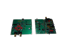
Nothing out of the ordinary, Peter Daniel boards, single transformer, Tech-DIY transistors and other bits, HiFi2000 chassis.

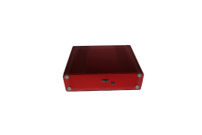
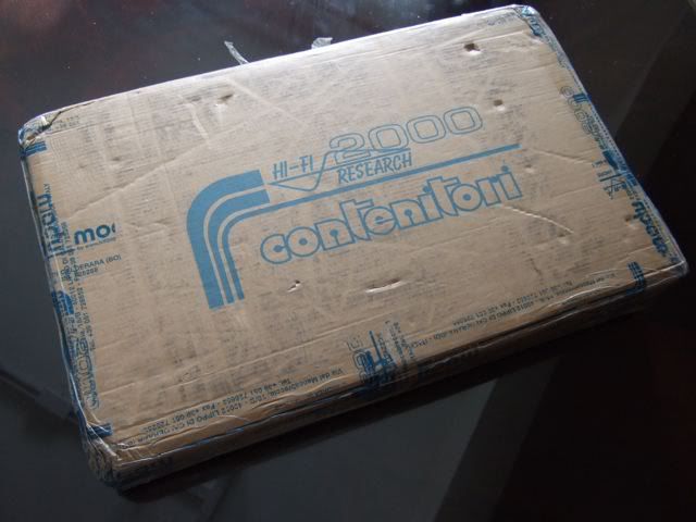
I have collected all the pieces and finally today the chassis arrived from Italy! I am ready to start!

DSCF3561.jpg

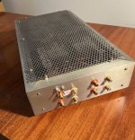
This is From Modushop.biz, it's a "Pesante Dissipante 4U depth 300 mm" (6 1/2" tall x 11 3/4" deep x 19" wide) Which will have a different specific number depending on color and faceplate thickness. I needed to get the shallow(300mm) case, if you have the room for it, you could get the 400mm deep.


DSCF3564.jpg


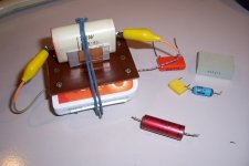
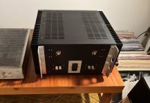
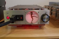
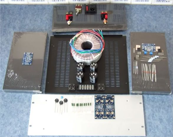
Here is the obligatory "armory" photo. Only one of the amp channels shown.

DSCF3567.jpg

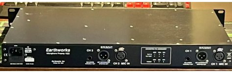
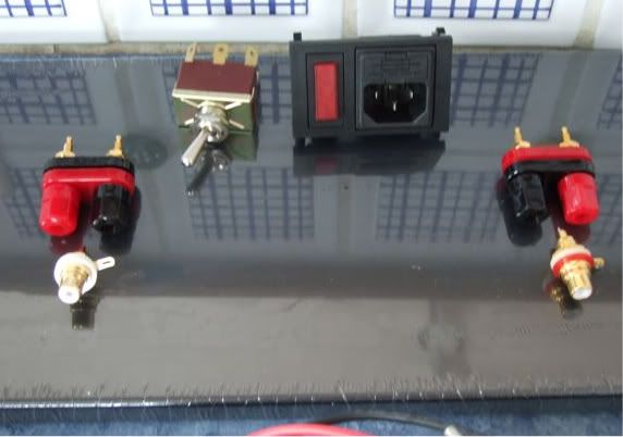
The rear panel. I thought I ordered an Inlet Module with a switch, but I didn't read the datasheet well enough, and it has a neon light power indicator instead. Oh well. Luckily I have a couple of nice bat-handeled switches, I will use one here. The Jacks and RCAs are also from my box, I think they are Vampire.

DSCF3565.jpg

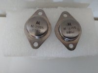
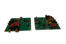
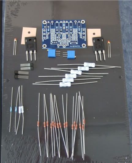
Here are the contents of the Tech-DIY F5 kits, the Peter Daniel's boards, and a couple of silpads.

DSCF3566.jpg


DSCF3566.jpg

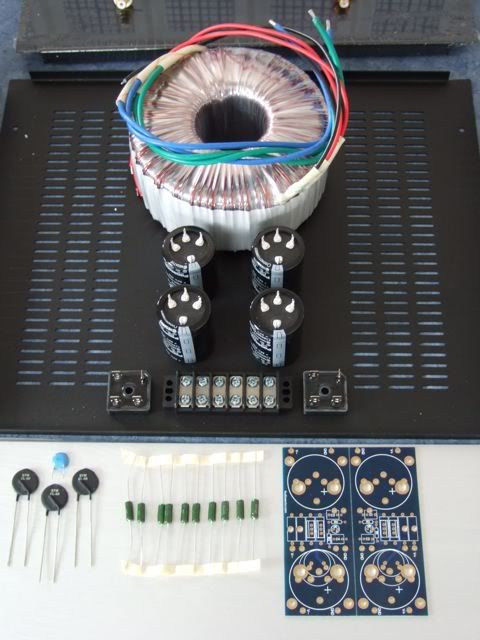
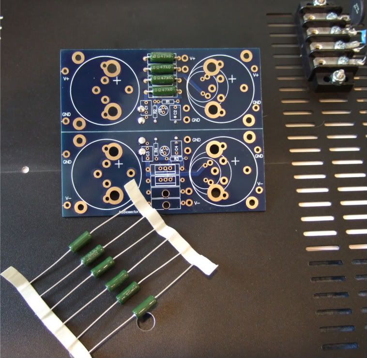
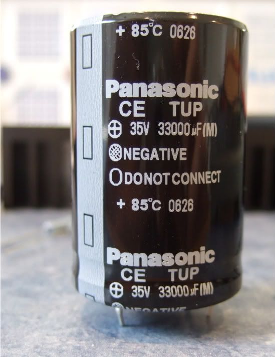
The PSU components. Vishay rectifier blocks, Peter Daniel PSU board, resistors, 33,000uf capacitors, CL-60 thermistors, and a big-honkin' 600VA transformer.

When I was determining the transformer size necessary I must have had a brain-sneeze, I must have only thought of one secondary! Oh well, it was only $20 more than the 'proper' (400VA) size. The 4-pin caps will work on the board with just a bit of modification.

DSCF3562.jpg

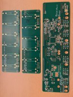
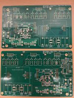
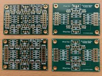
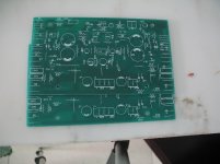
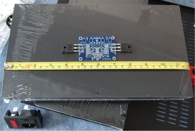
If you were wondering, the Peter Daniel boards are very small. Also very nice!

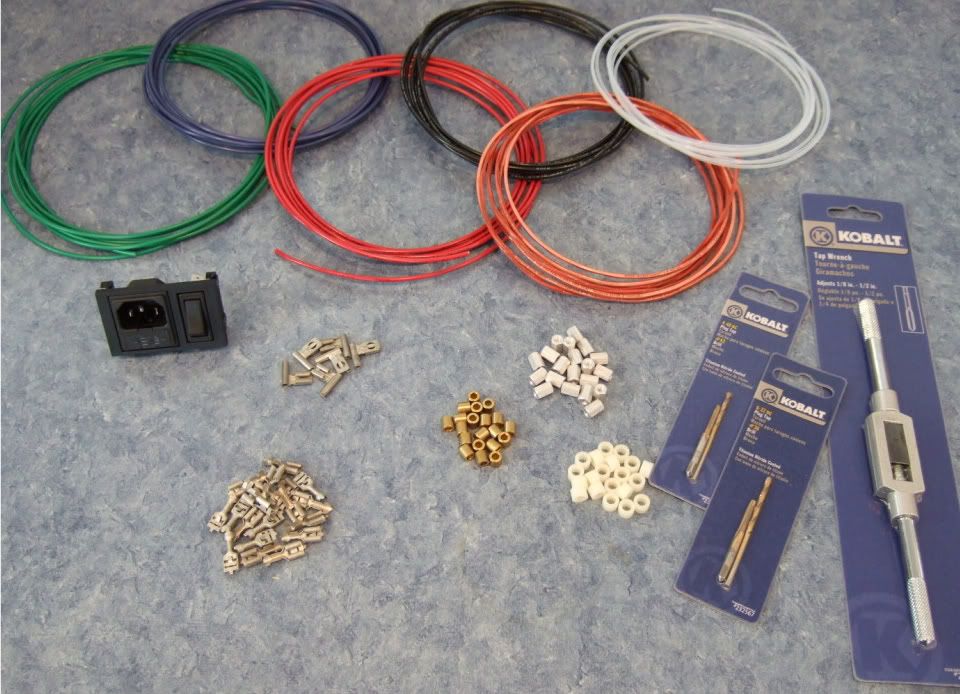
As mentioned earlier I needed to get a few more things before proceeding with the build…

DSCF3570.jpg

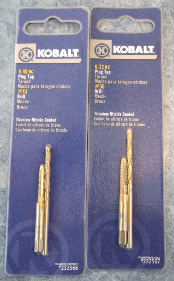
Specifically, wire, connectors, standoffs, spacers, and a tap set. (also a couple of other things not photographed.)

DSCF3573.jpg

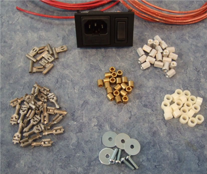
As I am not exactly sure what will be the best standoff/spacer, I bought an assortment. Brass, Nylon, and 'real' 6-32 thread standoffs. Also shown are the 1/4" connector spades, the 6-32 bolts and fender washers for mounting the power transistors.
Also note the Power Inlet module now has a switch!

Not photographed is a big pile of 4-40 hardware for mounting the boards, as well as a few more 6-32 bolts for the rectifier blocks and barrier strip.

DSCF3574.jpg

The store I went to didn't have taps without the drill bits, but since they are the exact size for the tap, I didn't see any disadvantage in getting them.

DSCF3576.jpg

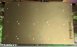
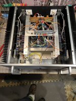
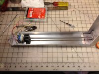
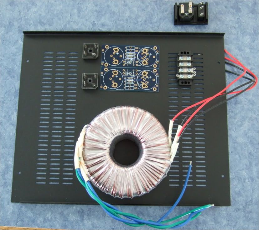
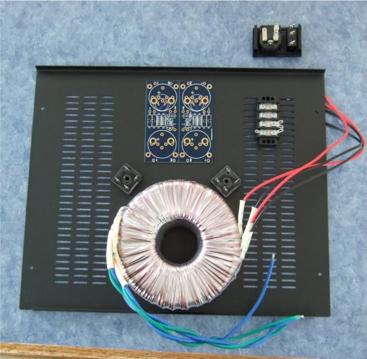
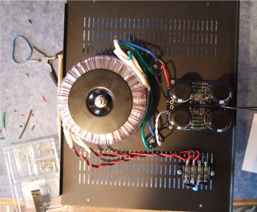
Trying to detemine the best layout for the bottom panel. The Transformer is positioned in the front of the case.


DSCF3577.jpg

I like this better, it will lead to more symmetrical wiring. Which although not necessary, appeals to me.

If I had the 400mm deep chassis I would also have the power inlet and the barrier strip on the centerline.

I think it is a good idea to leave the chassis vents unobstructed, to keep the heat exchange/airflow as good as possible.


Today I got some drilling done. A lot of effort with not much to look at...

DSCF3578.jpg


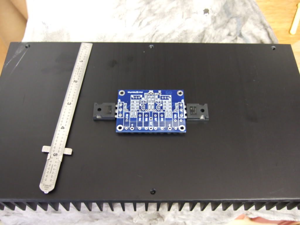
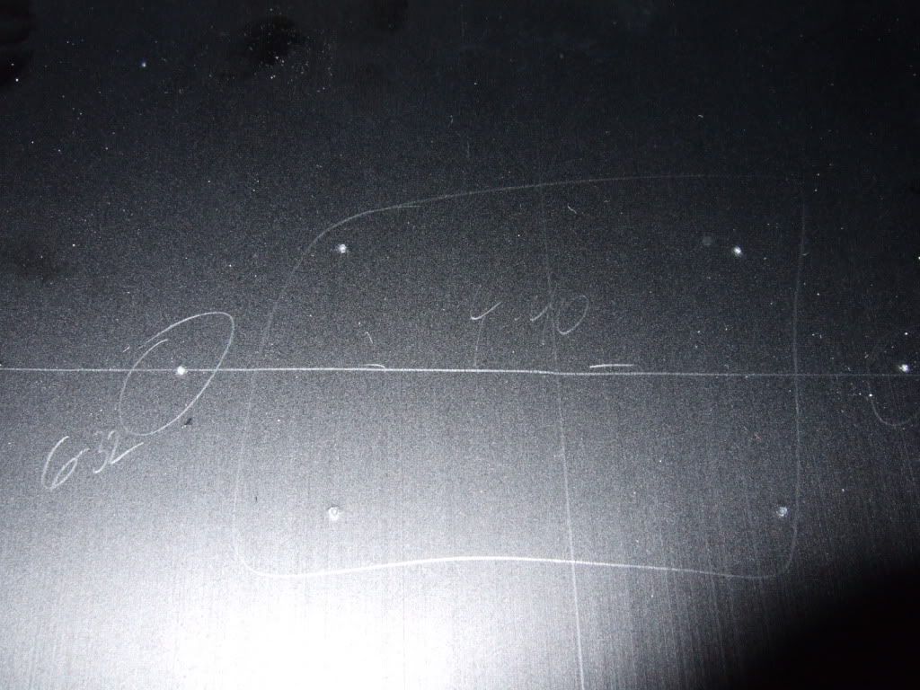
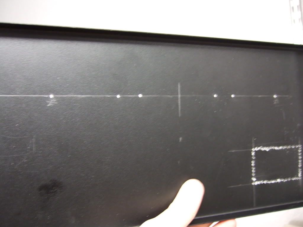
This is the amp board and the 2 power transistors. They will be mounted to the middle of the heatsink.

DSCF3580.jpg

Once the hole locations are marked, I made some starter holes with a set punch. The 4 in the middle will be 4-40, the two on the outside 6-32

DSCF3582.jpg

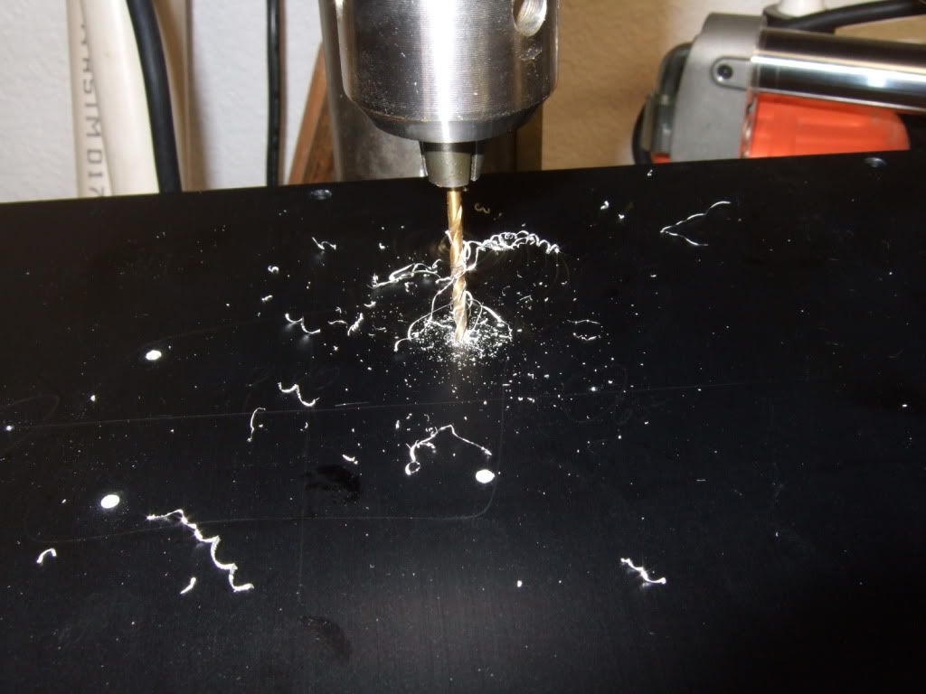
Drilling. Wear safety glasses!
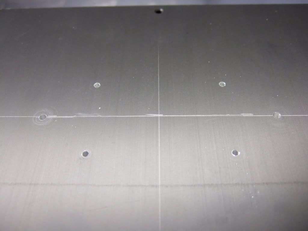
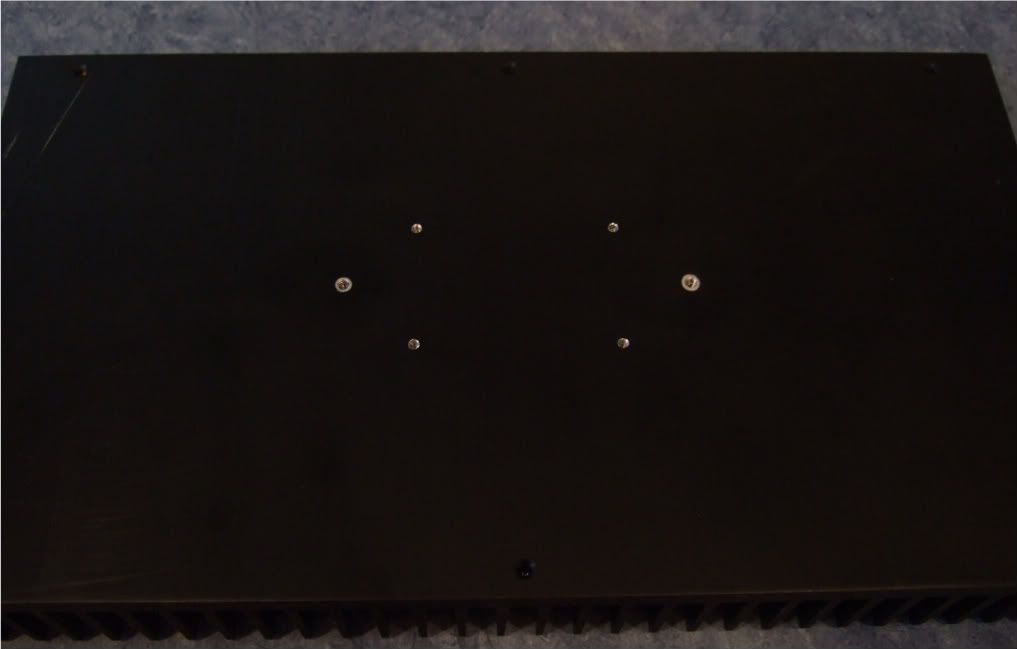
DSCF3587.jpg

Drilling complete.

DSCF3584.jpg

My friend was kind enough to tap the holes.

DSCF3593.jpg

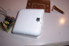
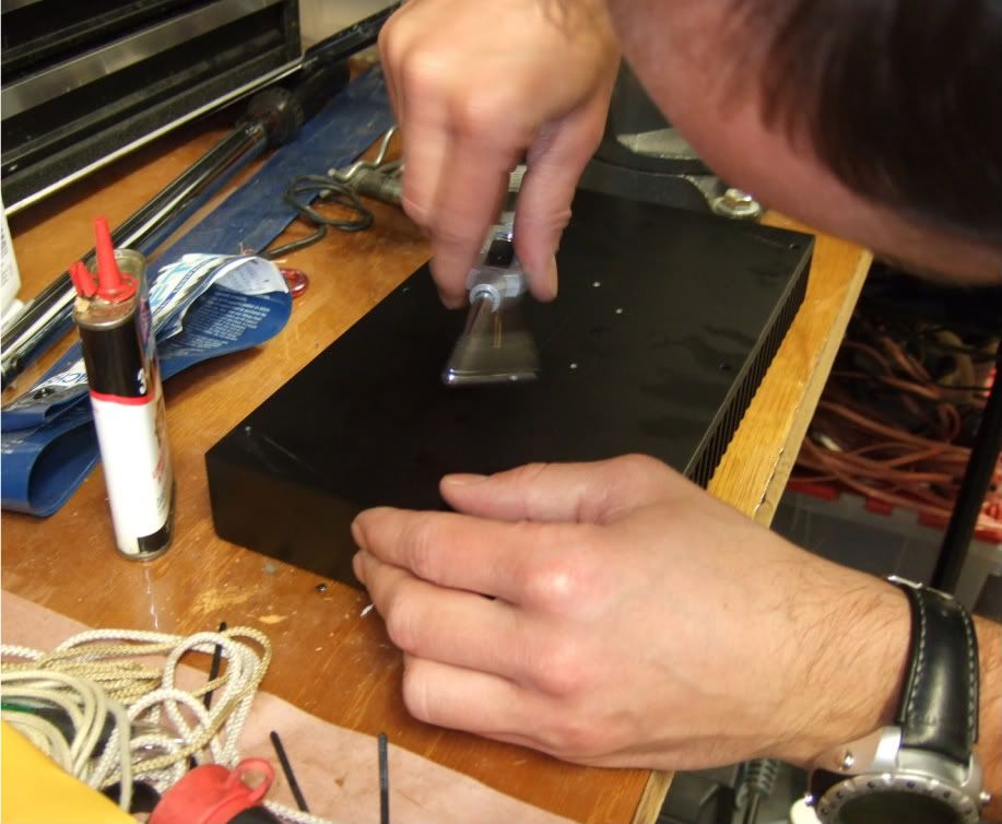
Pilot holes for the RC jacks and Speaker posts. Also the beginning of the IEC inlet module cut-out.

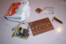
I have all I need in place to build the amplifier circuit and mount it to it's heatsink -

DSCF0002-1.jpg

Here is the heatsink, with the holes sanded smooth and cleaned with rubbing alcohol to remove the last oil and sandings/shavings.

DSCF0003-1.jpg

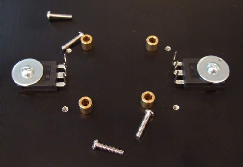
Here is the hardware, 6-32 bolts and fender washers on the transistors, brass spacers and 4-40 bolts on the board

DSCF0004.jpg

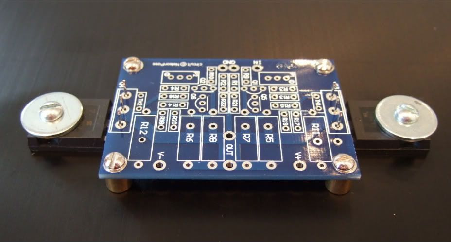
A dry run, to check fit.

DSCF0005.jpg

Spacing looks good! Now to complete the board...

DSCF0006.jpg

Stuffing the board. Have your meter at the ready and measure everything before soldering!!! It will save headaches later!!

DSCF0007.jpg


DSCF0008.jpg


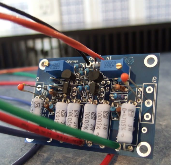
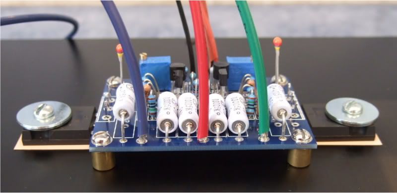
OK, the board is stuffed and the wires attached. My color coding is as follows;

Black - ground
Blue (V-)
Green (V+)
Red (+) out
Red/black twisted pair in orange jacket is input + and -

I like to have the wires much longer than needed to help facilitate neat and tidy wiring later.

DSCF0009.jpg

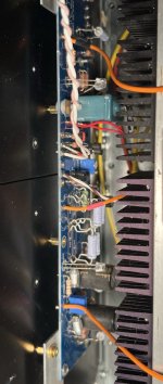
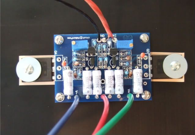
On the heatsink with silpads attached.

DSCF0010.jpg

In this photo you can see the following -

The thermistors are not bent down yet, as I need to get some loctite for the threads before I am actually done... Same with the transistors, they are not soldered and trimmed.

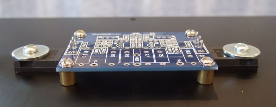
The two 3W resistors on the outside of the PCB (R11 and R12) are standing up off the board so that when it becomes time to set bias, I can easily connect leads across the resistors.

DSCF0080.jpg

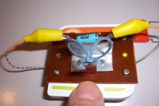
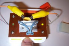
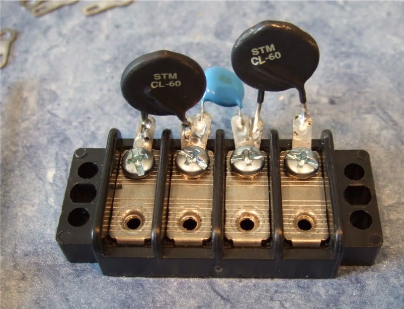
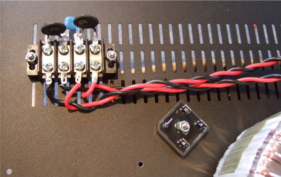
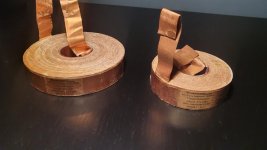
Here is the terminal block showing the thermistors and the capacitor.

DSCF0082.jpg

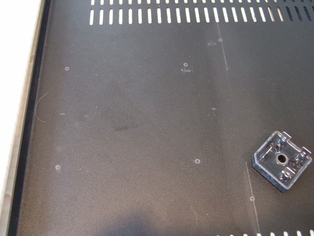
Marking the chassis bottom for the PSU board, rectifiers, and (not in photo) the transformer bolt.
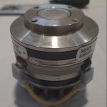
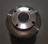
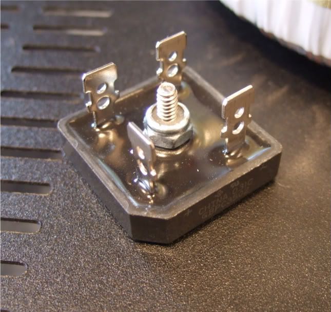
DSCF0095.jpg

Rectifier block

DSCF0094.jpg

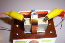
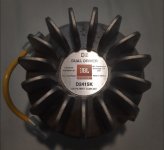
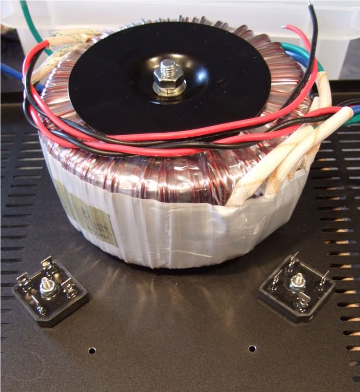
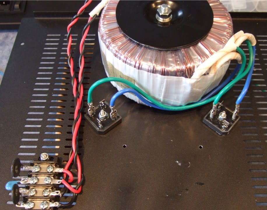
The monster Antek AN-6218

DSCF0083.jpg

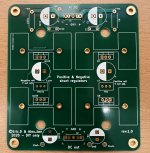
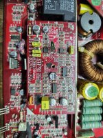
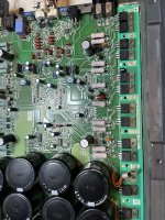
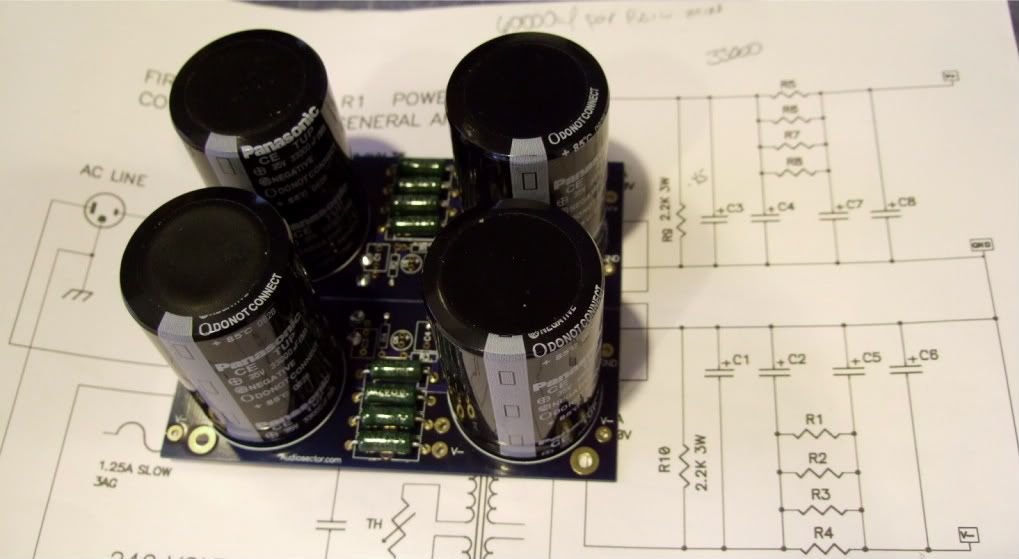
Stuffing the PSU board

DSCF0084.jpg

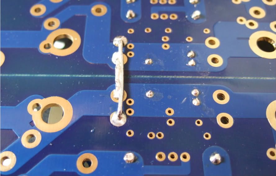
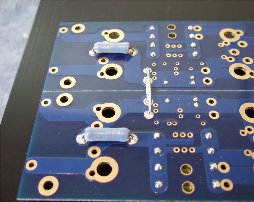
Remember to connect the grounds... Peter Daniel suggests you do it here. I am not sure if you need to have 2 jumpers like I am showing, but a good, low-impedance connection is always a good thing on a powersupply.

DSCF0088.jpg

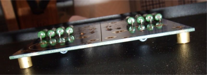
I mounted the bleeder resistors to the bottom of the board. You probably could do it on the top if you had physically smaller caps.

DSCF0091.jpg

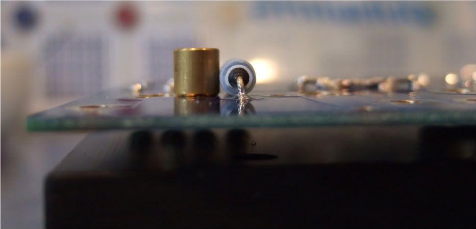
One thing that needs to be checked is if the spacers are taller than the bottom components. Looking good!

DSCF0090.jpg

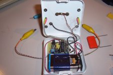
I needed to hold my camera upside-down to get the flash in a place where it could illuminate the bottom. This shows that there is plenty of room under the board.

DSCF0086.jpg

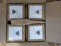
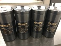
The capacitors I am using.

DSCF0087.jpg

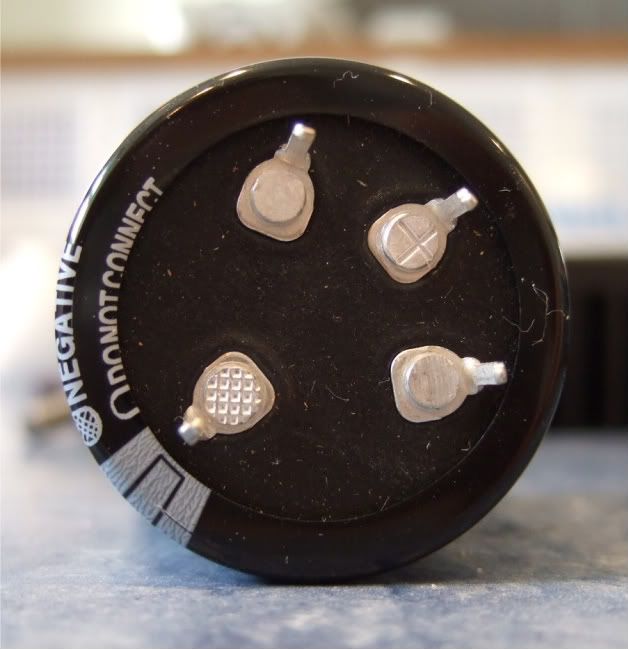
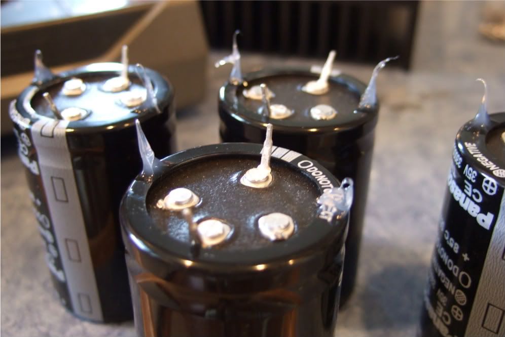
These are a 4-pin cap, and so the unmarked (and unconnected) pins need to be trimmed off.

DSCF0093.jpg

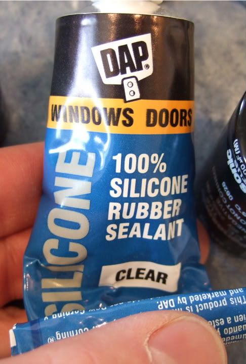
These caps are a bit big to be mounted just by two solder pins, so I am using just a small dab of silicone on the case to help stabilize and support the cans. Also note that the unused pins are now trimmed.

DSCF0092.jpg

The silicone

DSCF0096.jpg

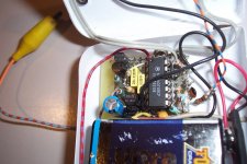
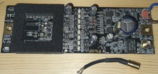
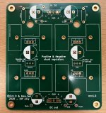
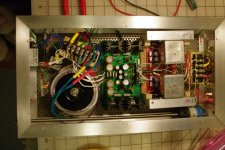
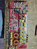
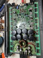
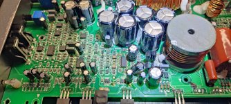
The complete (except wires) PSU board.
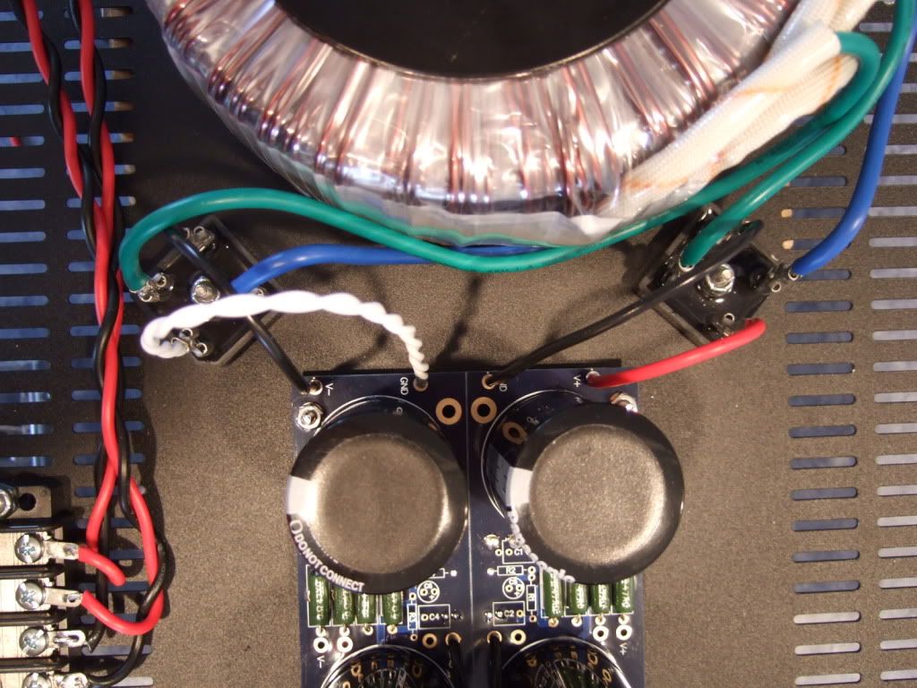
Wiring the PSU -

DSCF0098.jpg

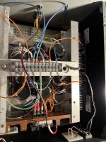
The primaries attached to the barrier strip. AC from the power inlet module will attach to the center two connections of the barrier.
Note the rectifier blocks -- the notched corner is "+" DC, it's opposite is DC "-" The other corners are AC in.

DSCF0099.jpg

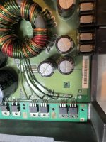
The leads of the secondaries connected to the rectifier blocks. Here you can see the AC connected to the AC in tabs of the rectifiers.

DSCF0105.jpg

PSU board connected to the rectifiers.

DSCF0103.jpg

The PSU completed except for AC in. This will be from the power inlet module. The black leads at the center of the PSU board will be the speaker negative connections.

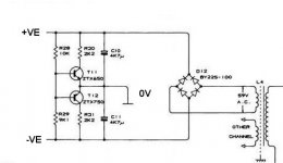
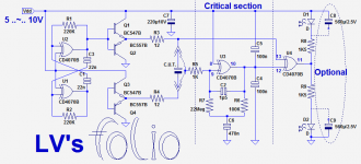
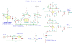
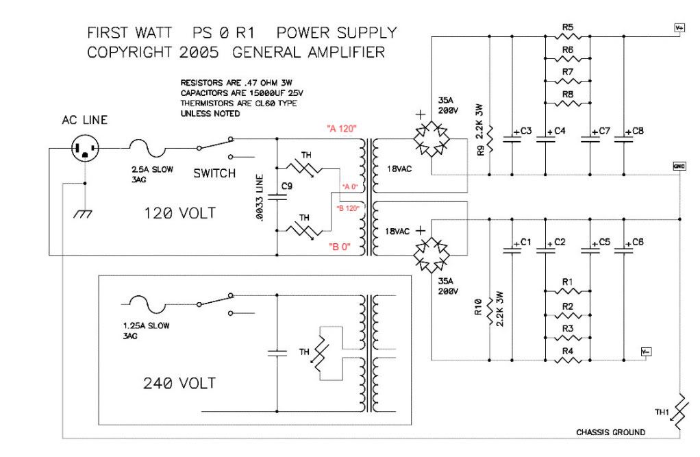
Let's look at the PSU schematic just to make sure everything is OK... Remember that I am wiring it for 120v operation, so the transformer primaries are in parallel. People wiring for 240 with a transformer like this, please ignore.

F5PSUschematic.jpg

Notes in red are mine.

Look at the connections of the transformer primary, through the thermistors and line cap, to the mains.

Hot AC is connected to the "120" (which in my case is the red leads on the primaries) One red primary is connected to AC hot through a thermistor.

Neutral AC is connected to the black "0" leads, one of which is connected to the AC through a thermistor.

AC Hot and Neutral have a cap across the leads.


So, yes, the AC will be connected to the center 2 posts, which is across the cap.

DSCF0098.jpg

Left to right we have post 1, 2, 3, 4

POST 1 - Transformer primary 'B 0' which will be connected to AC Neutral at post 2, through the thermistor between post 1 and 2.

POST 2 - AC Neutral in (not shown in photo), connected to Transformer primary 'A 0" , a thermistor to post 1, and a line cap to post 3

POST 3 - AC Hot in, connected to transformer primary "B 120", thermistor to post 4, and line cap to post 2

POST 4 - Transformer primary "A 120", connected to AC Hot through the thermistor to post 3

If you look at the red and black wires in the photo you will see that the Mains AC must to pass through a thermistor to connect to each of the 2 primaries. And that is the point of them, to keep inrush under control during powerup.


UPDATE - (This is the only place I can edit this thread) Please look here (post #401 if this thread) for the new, much quieter grounding scheme -- http://www.diyaudio.com/forums/pass-labs/188691-illustrated-guide-building-f5-9.html#post3161231

  • Locked
Jensen/Duelund copper foil inductors

I have some NOS Jensen copper/paper/wax inductors after an abandoned project.

6 pcs 3.5mh 12 AWG
2 pcs 1.0mh 12 AWG

All unused.

They are sold as Duelund Wax copper foil now, at a cool £392 pcs for the 3.5mh and £229 pcs for the 1.0mh.

I have no idea how to price these, so send me an offer if you are interrested.

Attachments

  • jensencoils.jpg
    jensencoils.jpg
    81.8 KB · Views: 192

Any recommendations amongst these DAC boards?

I am looking to build a modern DAC with USB as well as optical and/or coaxial input and the ability to handle a wide range of input standards - but primarily 44kHz 16-bit for now. My aim is to play with better power supply, clock and output stages. I don't want to spend too much on my first attempt but I am aiming at better than just good sound quality. Ideally I wanted current-output DACs so that I could do my own I/V stage (discrete or quality transformers). Most are voltage output except the ES9038.


If anyone has experience of any of these boards then I would like to hear about it. Buying from China on eBay always runs the risk of fake and/or QC-fail parts being used, hence my interest in real world experience.

Any recommendations for current-output DACs that I haven't yet been able to find on eBay also welcomed. These seem pretty hard to find now.

Thanks in advance.

M

Dave Berriman DBS6 information wanted

My brother has obtained a pair of Dave Berriman DBS6 bookshelf speakers. They use a proprietary 8" woofer and a Morel MDT30 tweeter. The design for these was originally published in Hifi News and Record Review. We have a scan of the article but it's unreadable, including the date of the magazine. It looks like February 1992 but could be anything really.

If anyone knows the issue these were published in, that would be very helpful. Also details of the crossover, as there a couple of strange things going on that look as though whoever built it originally wired it up incorrectly. Ultimately we will do some measurements and do a design from scratch but a good starting point would be useful.

Thanks for any info that anyone might have 🙂

Upgrading panel mount RCAs and 5-DINE

Hi there,
I recently acquired a Rotel RP-3000 that I'm having refurbed and had a question on higher-quality panel mount connectors.

I am sending the tonearm out to get rewired, and it's wired to old panel mount RCA's and and 5-DIN connector. Is there anything "better" out there? I found a Neutrik 5-PIN female panel mount connector, but I have no idea if that's an improvement on what it already on the turntable. Cardas makes 5-PIN DIN connectors, but not in panel mount.

Also looking to get some copper/gold-plated RCA's, but I can't seem to find those in a panel mount option.

Thanks in advance.
Projects by fanatics, for fanatics
Get answers and advice for everyone wanting to learn the art of audio.
Join the Community
507,650
Members
7,882,730
Messages

Filter

Forum Statistics

Threads
405,964
Messages
7,882,730
Members
507,650
Latest member
Sanjiev