Hi, I'd like to make sure I'm using Hornresp properly for a new build.
It worked very well in predicting the response of a vented PPSL I built a few years ago, but there have been some changes in HR I'm not sure I understand.
Here is a version where the slot has parallel walls. The slot is roughly 19" x 11".
I used the wizard to make an Offset Driver , and put the following into the Horn input fields.
Do the horn segment inputs look correct?

Here is a version where the slot is narrow in the back, and wide in the front. With the drivers in about a 90 degree angle like a pict of the sub below.
Slot is about 3" wide in back, and 21" wide in front.
Do the horn segment inputs look right for this version?


I'm not asking folks to check my math (areas and length), just trying to make sure i'm going about it correctly.
Thanks !!!
It worked very well in predicting the response of a vented PPSL I built a few years ago, but there have been some changes in HR I'm not sure I understand.
Here is a version where the slot has parallel walls. The slot is roughly 19" x 11".
I used the wizard to make an Offset Driver , and put the following into the Horn input fields.
Do the horn segment inputs look correct?
Here is a version where the slot is narrow in the back, and wide in the front. With the drivers in about a 90 degree angle like a pict of the sub below.
Slot is about 3" wide in back, and 21" wide in front.
Do the horn segment inputs look right for this version?
I'm not asking folks to check my math (areas and length), just trying to make sure i'm going about it correctly.
Thanks !!!
#1 is correct, remember though that for OD the driver entry into the horn (ie, the middle of the drivers in your case) is at S2, so for a layout like your second option you need to continue the expansion to S3.
In this case, assuming your S3 is right, then you'd change S2 to the average of S1 & S3, and set L23 to account for the remaining half of the depth from the middle of the cab to the front.
HTH,
David.
In this case, assuming your S3 is right, then you'd change S2 to the average of S1 & S3, and set L23 to account for the remaining half of the depth from the middle of the cab to the front.
HTH,
David.
Won't make a huge difference, but the concave volume of the cones (VTC) also impacts the "horn".I'm strongly considering the angled approach
On undersized cabinets like the Fulcrum depicted, the VRC reduced by the driver on the inside and increased on the plenum may be a fair percentage of the distribution.
There is a Hornresp tool "Driver Front Volume" that you can use to determine that volume.
The Tools menu command is enabled when the input parameters window is in edit mode. The tool can also be selected by double-clicking the Vtc or Atc label or text box in edit mode.
"Driver Front Volume" calculates the effective air volume between the driver diaphragm and the front plane of the driver, given D1 the inside diameter of the mounting sealing strip, D2 the inside diameter of the diaphragm suspension, D3 the diameter of the dust cap, H1 the thickness of the sealing strip, H2 the perpendicular distance from the front plane to the edge of the dust cap, and H3 the perpendicular distance from the front plane to the centre of the dust cap.
The driver front volume calculated by the tool must be manually added to Vtc, it is not added automatically.
Double-click the front volume value to show front cross-sectional area.
The center volume of the banana (Zeppelin?) shaped port can also be made part of the VRC, also could be used for side handle cut-out boxes.
Art
Thank you very much Art,
I need all the help/tips I can get, picking up HR again after a long layoff.
(layoff other than for sealed or plain bass-reflex subs)
It's easy to see how undersized the Fulcrum model is, that I used to show what I'd like to build.
(US221-4. https://www.fulcrum-acoustic.com/wp-content/uploads/2019/11/Prod-Spec-US221-4-v9.pdf)
I plan to put 18n862's in roughly the same size box, same angled orientation, but without any ports.
A slot port facing forward will go in a same size box below the driver box.
But it will all really be just one box, separated only by bracing. 36"W x 44"H x 29"D.
I'm figuring over 400L net after all bracing etc. So like you said, driver volumes probably don't matter much..especially since it won't be undersized.
It will make a "sub cart" with 4 large castor wheels. I've come to like the sub carts...i can roll around the entire sub and whatever synergy is on top of them, from indoors to out. A pict of the cart the new PPSL will replace is below, with big syn11 on top.
Here's a simple drawing to show the center port location in bottom of sub.
Do you see any problems with this sub idea?

I've always wanted to build a PPSL with the drivers mounted vertically after our discussions about cone sag years ago. But the anti-sag circuit worked well, (when I remembered to switch it on after using the subs lol). And I did rotate the drivers about every 1.5 years. They measure centered still....yay!
The sub carts I have now, simple double 18" reflex have downward firing ports. Can't say I like that...
I like the feel of a ports output when cranking.
Also, the birch ply I can get now that baltic (russian) is unavailable, that went into the sub carts, needs more bracing than I thought (from experience with good BB) Sub is very clean till really cranked, but then resonances pop up.
And last complaint with them, they are just too damn big for me to fit 3 into the room.
I want to go back from the huge syn11's stereo, to 3 syn10's in LCR, whose bit smaller size can fit into my room.

Anyway, three new angled slot subs on the way.
I figure at a 90 degree opposed angle I'll get 0.707 reduction in vibration, vs parallel slot loading.
I need all the help/tips I can get, picking up HR again after a long layoff.
(layoff other than for sealed or plain bass-reflex subs)
It's easy to see how undersized the Fulcrum model is, that I used to show what I'd like to build.
(US221-4. https://www.fulcrum-acoustic.com/wp-content/uploads/2019/11/Prod-Spec-US221-4-v9.pdf)
I plan to put 18n862's in roughly the same size box, same angled orientation, but without any ports.
A slot port facing forward will go in a same size box below the driver box.
But it will all really be just one box, separated only by bracing. 36"W x 44"H x 29"D.
I'm figuring over 400L net after all bracing etc. So like you said, driver volumes probably don't matter much..especially since it won't be undersized.
It will make a "sub cart" with 4 large castor wheels. I've come to like the sub carts...i can roll around the entire sub and whatever synergy is on top of them, from indoors to out. A pict of the cart the new PPSL will replace is below, with big syn11 on top.
Here's a simple drawing to show the center port location in bottom of sub.
Do you see any problems with this sub idea?
I've always wanted to build a PPSL with the drivers mounted vertically after our discussions about cone sag years ago. But the anti-sag circuit worked well, (when I remembered to switch it on after using the subs lol). And I did rotate the drivers about every 1.5 years. They measure centered still....yay!
The sub carts I have now, simple double 18" reflex have downward firing ports. Can't say I like that...
I like the feel of a ports output when cranking.
Also, the birch ply I can get now that baltic (russian) is unavailable, that went into the sub carts, needs more bracing than I thought (from experience with good BB) Sub is very clean till really cranked, but then resonances pop up.
And last complaint with them, they are just too damn big for me to fit 3 into the room.
I want to go back from the huge syn11's stereo, to 3 syn10's in LCR, whose bit smaller size can fit into my room.
Anyway, three new angled slot subs on the way.
I figure at a 90 degree opposed angle I'll get 0.707 reduction in vibration, vs parallel slot loading.
No problems, other than the parallel horn walls may "honk" a bit, but that would be out of band.Here's a simple drawing to show the center port location in bottom of sub.
Do you see any problems with this sub idea?
I like the L'Acoustic laminar flow vents, kind of like a bigger version of what Dave's Fulcrum subs are using.
Some discussion in this thread:
https://www.diyaudio.com/community/...ront-loaded-br-subs.406026/page-4#post-754401
I expect you will complete your subs before the OP there starts his

My old quad 15" L4 design is approximately the same volume as you plan for your dual 18".Anyway, three new angled slot subs on the way.
I figure at a 90 degree opposed angle I'll get 0.707 reduction in vibration, vs parallel slot loading.
The L4 was 30" deep, the drivers "V" at the back of the cabinet. The "phase ramp" between the driver pairs eliminated standing waves, sounded quite good crossed at 200Hz where it balanced the output of the quad 12" horn with two 2445 and two 2425 in the same size cabinet above it. Of course, that was in the ~40 Hz era, and the bass cabinets were flown or stacked with the high cabs...
Of interest, we also used just a pair of the 15" (diagonally loaded worked best) in the same cabinet as a "lite" version for lower volume gigs, the low end output was the same, the cabinet was flat rather than the rising response of the quad.
With a deeper narrower "horn" like the L4, vibration would further reduce, drivers get closer to physical time alignment with the top MEH, and the exit would be about the width of the port, which would look groovy
Art
I like the L'Acoustic laminar flow vents, kind of like a bigger version of what Dave's Fulcrum subs are using.
Some discussion in this thread:
https://www.diyaudio.com/community/...ront-loaded-br-subs.406026/page-4#post-754401
I like the L'Acoustic vents too.
Mulled how much work it would be to make them with bendy board bent on some plywood arcs, and then how to brace them....and came to conclusion since box size really isn't too much of an issue, that they are worth the effort.
Although that said, if the laminar flow vents add effective port length, that would be helpful.
The 160 sq in slot port I'm planning, 19" tall x 8.5" wide x 24" long, I have terminating 5" from back wall. And would like to go closer, but afraid I'm getting too close.
I guess i could put shelves on both vertical edges of the port to gain more effective length, but i think the HR model looks ok chuffing wise with 24" long. (23m/sec).
Here's power within xmax, using 90 degree angle design still.


My old quad 15" L4 design is approximately the same volume as you plan for your dual 18".
The L4 was 30" deep, the drivers "V" at the back of the cabinet. The "phase ramp" between the driver pairs eliminated standing waves, sounded quite good crossed at 200Hz where it balanced the output of the quad 12" horn with two 2445 and two 2425 in the same size cabinet above it. Of course, that was in the ~40 Hz era, and the bass cabinets were flown or stacked with the high cabs...
Of interest, we also used just a pair of the 15" (diagonally loaded worked best) in the same cabinet as a "lite" version for lower volume gigs, the low end output was the same, the cabinet was flat rather than the rising response of the quad.
Those look like some really well thought-out, well implemented boxes. Nice !!!
With a deeper narrower "horn" like the L4, vibration would further reduce, drivers get closer to physical time alignment with the top MEH, and the exit would be about the width of the port, which would look groovy
I take it that the L4 deeper narrower horn had driver access panels on the back?
That's probably my biggest hesitation in going narrow....the anticipated need for access panels.
(The 18n862 are 10" deep. I have an 11" wide parallel slot on existing old PPSLs, which just gives adequate clearance getting both drivers into the slot)
I do think a narrower horn, along with a L'Acoustics style vent with the same width as the horn would look totally awesome.
But damn, that's a lot of work just for looks in my book. (lazy me) Lol
Yes, the access panels are parts "F" in the plan, the drivers are rear mounted. The "phase ramp" part "E" (and "G") would make front loading impossible, even with shallow drivers.I take it that the L4 deeper narrower horn had driver access panels on the back?
That said, your BMS 18N862 are 250mm (9.84") deep, the "V" would only need to be around 10.75" (273mm) wide at the baffle cut out point for the second driver to fit past the first.
With parallel walls, the front exit could be as little as 10.75".
With angled walls and the "V" coming to an apex, the angle could be <45 degree and still front mount the drivers.
That would be half (or less) the width of your proposed 90 degree mouth exit, similar to the port width if the drivers are near the exit.
Bendy plywood really makes building curves a lot easier.I like the L'Acoustic vents too.
Mulled how much work it would be to make them with bendy board bent on some plywood arcs, and then how to brace them....and came to conclusion since box size really isn't too much of an issue, that they are worth the effort.
Although that said, if the laminar flow vents add effective port length, that would be helpful.
For the size port you are considering, using two pieces laminated on a jig to 3/4" (18mm), I doubt any bracing would be needed, as it would be stiffer than plywood of the same thickness.
It has been established that square or round ports of the same depth and length behave nearly the same.
L'Acoustic appears to have proven their laminar flow square or rectangular exit ports have less loss ("port compression") using both less length and volume than an equivalent round port, in spite of the predicted port velocity being higher.
So compared to the 19" tall x 8.5" wide x 24" long slot port you are planning, a shorter, radiused port with a reduced exit dimension would give the equivalent Fb, using less volume.
Or like L'Acoustic, you could go "bigger and better" using a similar length port, which still would have about the same volume, but wider width.
The L'Acoustic KS28 dimensions (W,D,H): 1340 mm, 719 mm, 565 mm / 52.8 in, 28.3 in, 22.2 in.
Its Fb is~ 31Hz, the port near 18" wide by 20.5" tall.
Your larger volume, lower tuned box could use a port pretty close to their dimensions.
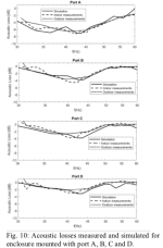
https://www.aes.org/tmpFiles/elib/20240217/20776.pdf
The radiused hourglass shaped laminar port "D" had slightly less measured loss outdoors (-2dB) than the larger volume and area port "C" (~-2.5dB), even though it's Strouhal "St" number was far lower, indicating higher port velocity.
" A ST ≤ 1 will lead to flow separation and vortices formation" does not seem to predict the laminar port's measured output loss at high drive levels.
Whether you make the ports with a curved radius, or a three piece approximation using straight plywood, it seems to be worth the effort for a craftsman with your skills
Attachments
Thanks for all the encouragement and food for thought, Art.
I have a 2/3 of a sheet of bendy board left over from another project that I've been toying with idea of making a proto L'Acoustics port.
But I dunno, seems like too much work in hope of too little gain. (I mean, I refuse to put secondary flares on my syn builds anymore.)
I think I'll just enlarge the rectangular slot port a little more and call it quits there.
As far as the angle between drivers, still not sure. The syn10s the subs will be going under are 36" wide, just like these new subs.
The syns have a 90 degree horiz horn. I'm thinking it might look pretty good to just have the 18"s at the same angle.
But I am going to play with hornresp and see how narrower angles sim before making a decision. I hope to maybe start building tomorrow
My very preliminary conclusion of port geometry tests was that the strouhal number should be referred to the port opening surface radius (not the smaller center radius or the respective comparable "radius" of a rectangular surface). Thus the strouhal numbers in the table shown would be different. flared rectangular port D has a bigger opening surface than port B and therefore a higher strouhal number.even though it's Strouhal "St" number was far lower, indicating higher port velocity.
Last edited:
Hi Art,
hey the more i think about it...the less i think i need to be concerned with chuffing.
I'm planning 42% port area to Sd, and with the big port to Sd ratio i've been using on all the vented subs I've built.
Can't say I've ever been bothered with chuffing...certainty not over the mains SPL levels it takes to achieve chuffing. Seems well masked if even a prob.
But I totally get why L-Acoustics or any other prosound provider is doing everything they can to make the smallest, lightest box, with most output they can.
I just don't have to worry about those constraints, so I'm Inclinced to go with a big butt port, albeit less than today's optimal.
Mark,How long would you make flares? On the diagonal? And how long would you keep the straight section?
(Assuming same port at 24" long, and 8.5" wide x 19" tall.
Would you make the flares equal on both ends? thx
Flared ends will give a bit more uncompressed output, the main reason for the L'Acoustics ports.
At your low 28 Hz Fb, +2 dB is about the same difference as +4 dB at 1kHz.
Not much more work, and will match the angle of your MEH..
While you made your port decision in #14, I was writing all this up in answer to #12
I would make the flares ~equal on both ends.
As a guess, ~half of the 45 flare depth extends the straight port length.
That said, a Hornresp sim that matched the "Bow Tie Sub" measured output required a longer port than the actual length including the flares..
The 4th order bandpass Bowtie Sub put all the output of a pair of LAB12" through the port, 13.5" x 3.5" in the center section.
I did distortion testing at 49v, (sine wave) and music testing with ~89v peak, max output of a SP4000.
In both sine wave and music testing (sub only) I don't recall hearing any chuffing or port noise.
Have fun!
Art
Last edited:
Thx Art,
Neat double 12" bow-tie sub. Good to hear no chuffing.
Here's the port outlet velocity at xmax from the hornresp set in #8. I gotta believe I'll be fine.
Well, project set sail today. Sawdust. Using my last precious sheet of 3/4 baltic birch to make the horn baffles for 3 subs.
Yep, fun time !

Neat double 12" bow-tie sub. Good to hear no chuffing.
Here's the port outlet velocity at xmax from the hornresp set in #8. I gotta believe I'll be fine.
Well, project set sail today. Sawdust. Using my last precious sheet of 3/4 baltic birch to make the horn baffles for 3 subs.
Yep, fun time !
Hey Art, got the first one (out of three) out on the driveway yesterday.
Here's a quick grab i could make. Wind and company wanting to come onto driveway........dang it.
Just a 120Hz steep lin phase low pass; and two small peq cuts, 88Hz -1.2dB, BW=1, and 100Hz -1.8dB, BW=0.2. No hpf.
So far so good. Will measure LEQ sensitivity over entire bandwidth, which I view as a paramount spec,
and then go to stressing her and see how she breathes.
Thx BP1 & Art,
Hornresp says Helmholtz is 26.8Hz.
Can't believe i forgot to take an impedance sweep....it's normally THE first measurement of a new sub.
I'd take one right now, but the drivers are out for painting the box. Will post when back in.
Here's final inputs as built...

Lpt is 24", but I think it will behave a little longer, because it opens into rear wall with only 4.5" to the wall.
So I'm guess impedance low at about 25Hz....we'll see...
Hornresp says Helmholtz is 26.8Hz.
Can't believe i forgot to take an impedance sweep....it's normally THE first measurement of a new sub.
I'd take one right now, but the drivers are out for painting the box. Will post when back in.
Here's final inputs as built...
Lpt is 24", but I think it will behave a little longer, because it opens into rear wall with only 4.5" to the wall.
So I'm guess impedance low at about 25Hz....we'll see...
- Home
- Loudspeakers
- Subwoofers
- Need Hornresp help with new push-push slot loaded build