Willsenton R8 Owners: Important bias board safety mod

Of all the things I have seen about mods for this amp, the issue in this post is an important one for reliability and safety!

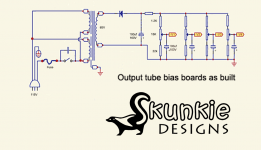
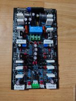
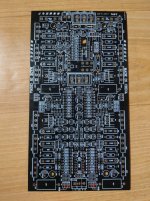
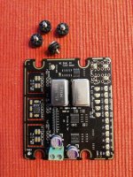
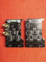
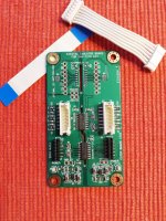
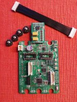
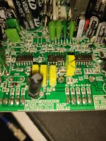
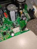
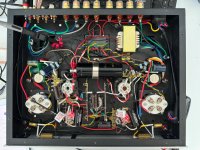
The design of the output tube bias boards leaves out an important component, a "fail safe" or "emergency pull down" resistor in case the wiper on the potentiometer goes open. This can easily happen if some dust or dirt ends up inside it, corrosion or it simply fails. Without this resistor, if the wiper goes open, the output tube red plates and all sorts of bad things happen. I've read several reports of this happening to this amp.

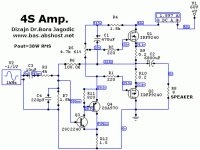
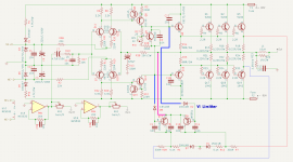
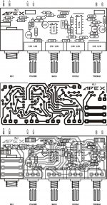
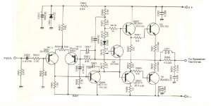
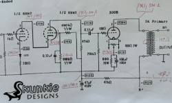
Attached are schematics showing as built, and then with a 100K "fail safe" resistor added. You can see more about this at the Valve Wizard page here: https://www.valvewizard.co.uk/bias.html

"R3 is an emergency pull-down resistor. This ensures that if the pot wiper fails to make good contact with the rack (because it is dirty or worn out, say) the grid leaks will effectively be connected directly to the raw bias supply through R3 instead, biasing the valves safely cold. "

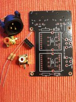
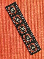
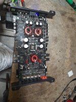
If you do nothing else to this amp, I highly recommend adding a pair of these resistors to the two bias boards. I uploaded a video showing how to do this.

Login to view embedded media

Attachments

  • R8-Bias.png
    R8-Bias.png
    52.6 KB · Views: 405
  • R8-Bias-SK.png
    R8-Bias-SK.png
    49.4 KB · Views: 341

How to do Bluetooth switch mod on ZK-TB21/ZK-1002T?

Hi there!

I have those amps and I like them, except for the fact that Bluetooth is available for pairing when AUX input is connected. I read that they can be flashed but this is most likely not possible (easy) with those boards and I see that it's not easy to get datasheets for the BT chip.

So: Where do you think I can make a mod to add a switch? Adding photos of the board, one is a close-up.

Edit: By a switch I mean where I can cut. I see the following options:
  • Find out where to cut and add wires for an external switch
  • Disable BT by placing the amp in a Faraday cage
  • Disable BT in the antenna connection:
    • Doesn't work for a switch because I would change the antenna design
    • Might fry something if I cut it because of RF power not going anywhere (not sure)
Suggestions welcome.

1678302330599.png

1678302273385.png


Thanks.

Small class A amplifier with THD below 0.0001%

Hello again, I built this amplifier some 6 years ago and after 2 years of listening evaluation I put it in my "prototype stock". Few days ago I got an idea how to improve mains frequency components S/N by changing just one track on the PCB - the signal GND track. And it has worked very well.

The amp uses modified output stage from ExtremA by Sander Sassen which was put in the loop of a good opamp. The output stage uses local NFB and has vanishingly low distortion below 0.001% itself, but quite high output impedance of 0.235 ohm. In the opamp feedback loop the distortion falls below 0.0001% and the output impedance becomes negligible.

Below is the circuit schematics, THD vs. power plots at 1kHz and 5kHz and the 1kHz spectrum. Output noise is 23uV over 20Hz-22kHz unweighted. This was measured with OPA637 at the place of IC1.

pma4sch.gif


classA_1k_thdpower6R8.png


classA_5k_thdpower6R8.png


classA_11W_thd6R8.png
  • Like
Reactions: decramer and mjona

Technics SU-V4X

Hi!

Since I had a v1X and it sounds acceptable, reading the posts on the forum (many thanks to SVI2004A for the inspiration) I managed to find a v4x, but only defective. The "safety operation" led it flashes quickly and the relay does not click. I checked the supply voltages and and I have the corresponding values (+/-44v, +/-16v, +5v). I put an audio signal in it and I find it at the input of SVI2004A, all audio settings are functional.
Does anyone know if I could still find an SVI2004A somewhere?

Thank you in advance!

Attachments

  • WhatsApp Image 2024-05-31 at 12.54.00_44e77fb7.jpg
    WhatsApp Image 2024-05-31 at 12.54.00_44e77fb7.jpg
    151.8 KB · Views: 70
  • WhatsApp Image 2024-05-31 at 12.54.00_819ae83d.jpg
    WhatsApp Image 2024-05-31 at 12.54.00_819ae83d.jpg
    125.9 KB · Views: 67
  • WhatsApp Image 2024-05-31 at 12.54.00_881204a7.jpg
    WhatsApp Image 2024-05-31 at 12.54.00_881204a7.jpg
    124.9 KB · Views: 70

Neverending projects - Updates as they (and random theories) evolve..

Many projects have accumulated during too many years and are in need of some building
- progress in the housing development is to be posted here from now on..

Suitable first pic: testing how FaitalPro 4FE42 and 3FE22 work together in the Bestway.
DSC08578.JPG
Comparison of 3 Faitals; 4FE42, 3FE25 and 3FE22 plus a Visaton FRS8M.
I wonder if anybody has ever tried to build a fun tapped horn using these 3 inch Faitals, they are built like a tank: triple XMech compared to the otherwise very nice Visatons!

DSC08583.JPGDSC08585.JPG
  • Like
Reactions: Randy Bassinga

End of life NE5532ADRE4

I just got this message form Mouser:

Mouser Electronics received a lifecycle change notification from the manufacturer regarding a product you had interest in or purchased within the last two years. Please click on the part number to view product details and similar products for replacements.​

ManufacturerPart #Mouser Part #PO#Part Status
Texas InstrumentsNE5532ADRE4595-NE5532ADRE432334702End of Life

SPU Cartridges and Transformers Thread

Finally bit the bullet and acquired a new SPU GM E MKII for my TD-124/II/Schick/cracked_slate_plinth.. 😀 Quite thrilled with it overall, do need transformers with more gain and a lower primary impedance although those 977 are doing a lot better than I expected..

It seems like they actually knew what they were doing back in the old days.. This is certainly by far the best sounding analog set up I have ever owned, and I think would stand up well against some very pricey modern competition - not that the comparison will ever get done.. 😀

I have a ZU and a DL-103D, neither of these cartridges come close to the SPU in detail, dynamics, imaging, speed, bass quality and quantity, etc... I also have an all original loaner SPU G/T E on hand which in its own right is pretty amazing - all the more so given its age, apparently these cartridges if treated with a little respect are very long lived..

Attachments

  • New Ortofon_resized1.jpeg
    New Ortofon_resized1.jpeg
    67.5 KB · Views: 1,700
  • New Ortofon_resized2.jpeg
    New Ortofon_resized2.jpeg
    69.8 KB · Views: 1,649
  • Like
Reactions: Osvaldo de Banfield

Hartke HA3500 Bias

Hi
I need some help with this amp. What is the bias setting for this amp. The schematic shows SVR302 as the bias pot, but it does not show the voltage or the bias points. Across which component or point do I take the bias voltage reading. One more issue is that, the transistors Q304, Q305, Q306 and Q307 are getting very hot when the amp is turn on. Is this normal, but the driver and power transistors are just warm. I amplifier is working fine, just what is bugging me is why just this 4 transistors are getting so hot. Is it normal and OK for them to get hot. Please assist.


Thanks

Attachments

Trying to Draw a Schematic from PCB and I’m seeking your perspective on this matter.

Hi there to everyone. Academically speaking, I know very little about electronics. YouTube and DIY audio websites have taught me a lot about amplifiers. I'm trying to sketch the PCB board schematic that came from China. It's been a little unclear! Using a 15 volt zener diode, the audio stage is linked. also quite unclear in the OP-Amp input section; PINs 2 and 6 should be the input. What do you guys think about how well-built this circuit was?

Thanks
opu

Attachments

  • PCB_China_6PairTR_NE5532.png
    PCB_China_6PairTR_NE5532.png
    202 KB · Views: 125
  • DSC_0238.JPG
    DSC_0238.JPG
    326.9 KB · Views: 118
  • DSC_0239 copy.jpg
    DSC_0239 copy.jpg
    501.7 KB · Views: 124

Focusrite 6i6 Scarlett interface

My Focusrite interface has developed an issue with the inputs. When I plug anything into either one of the front instrument input's I get an intermittent fault where the input just stops, the activity LED stops registering and I get a weird noise from my monitors. Sometimes it does it sparingly and other times (like in the video below) its pretty much continuous.
This happens whether the device is connected via USB to my computer or not (just monitoring the input). Playback seems to be unaffected, I can still listen to things I've already recorded in my DAW whether or not the fault is present.
I've tried different power supplies and I've tried various different TRS jack leads, it still happens, its definatly not an issue with the jack leads as it does the same with microphones. I've had it for a good few years but it hasn't been used much. Pretty disappointing really. Never had an issue before this,
I'm hoping it's a known issue and someone can advise on a repair. I'm pretty good with a soldering iron so if its a cap or something, I should be easily able to swap it out.
Here is a vid showing the issue, during the recording a bass guitar is plugged in and I'm hitting a string but as you will see, its not picking anything up except for brief moments where the LED activity meter starts to flash as normal with the hitting f the string. You can also hear the weird noise coming from the speakers.

Really hope there's a fix!

Login to view embedded media

LR4 - 1 period delay and DSP delay

Hi Everyone..

I'm planning out a center channel with a DSP plate amp, and I ran across something I had not been paying attention to. Per Wikipedia, the lower filter will be in phase but a period behind the next driver up.

So, help me do the math here, imagining an ideal LR4 electroacoustic crossover with 2 ideal and identical drivers crossed at 300 Hz. Does this mean the woofer will be 3ms further away from the mid??

Is it possible or desirable to compensate for this? That is, delay the mid by 3 ms, so that the 1 period delay vanishes??

Am I overthinking it or is this actually a thing that most people do already? 😀

Weak signal output of preamp

I am using REW to take some measurements

My issue is that I am getting a very weak preamp signal out to the drivers. With a 20 watt amp I can barely hear it. With a 100 watt amp on a 3 way I have to turn it up to max just to get it to 75 db

What am I doing wrong here?

Attachments

  • PXL_20240529_012022664.jpg
    PXL_20240529_012022664.jpg
    390.2 KB · Views: 89
  • PXL_20240529_012026903.jpg
    PXL_20240529_012026903.jpg
    424.4 KB · Views: 92
  • Screenshot 2024-05-28 202251.png
    Screenshot 2024-05-28 202251.png
    314.3 KB · Views: 86

Need schematic Chinese 6N1 6P3P showing voltages

This amplifier is not working anymore. Its the 110 v version. I have a schematic,I tested the power transformer and the voltages are ok. I need a schematic showing the voltages throughout the circuit. This will help in narrowing down the problem components. There is no sound at all from both channels. See update further in this discussion. There is in fact a faint sound

Network of Multiple MiniDSP units: Do they play nice together?

As the title says, if I am combining multiple MiniDSP units, will they all play nice together? For starters, do the the older devices work with the newest version of DC?

I am currently using the HTx unit, which I purchased to be an active crossover for a 4 way system. But now I'd like to expand into multi-channel, so I need a lot more channels of DSP!

I found a MiniDSP 4x10hd on ebay, and I realized that I would need 2 of the 4x10 units to get all the channels I need for a 7.1 system. The idea would be to use the HTx as an AVR replacement, and the 4x10hd units as the active crossovers. This is assuming the 4 way active main speakers, and the rest of the system are 2 way active speakers. (I'd need 18 channels.)

But how well will that work? I'm a little concerned that the 5 PEQs per channel on the 4x10hd might annoy me later. I can combine the input and output EQs, and further tweek on the HTx output EQs...but that's a lot of EQs to keep track of!

And I noticed that the MiniDSP units don't have a 12v trigger input, so it seems they are not intended to be networked together. Granted I could wire in relays to turn everything on and off with a 12v trigger, but that is becoming a little complicated.

Any thoughts or experience?

Personal teleportation device PCB help request

Hello all. Firstly, I hope the mods allow this where the design gurus roam

Would someone with the time and energy please help with the design of a PCB. This is for a teleporting device. An active device would be better. Maybe something with a calculator type solar panel and a numeric keypad. No batteries or connections. If there are LED's that light with movement, then would be awesome. I know its asking for a lot but if this can be etched in, "Enter passcode to activate portal", would be awesomer

The backstory is that kids from my lil daughter's primary school have come to believe that she can teleport, so of course she must let them 'accidentally' discover the device 😀

It would awesomer again if she can solder this herself as she has a strong interest in STEM and also the school electric and double bass player

Thanks and regards
Randy

Nakamichi TA-2A

The Nak is 36 years old, I am the original owner. It has an intermittent hum that can be manipulated by jiggling input rca (cd). Remote can turn volume up but not down (could be remote). I blue stuff-ed the pots, no problems with those now. I've looked inside and don't see anything terminal-yet, but it's probably time for some work. I'm in Ronkonkoma, Suffolk county, central Long Island, N.Y., is there a reputable shop nearby that I could trust do it right? I'm not a tech, just a paint by numbers tinkerer, I've built a few things, but I don't feel confident enough to tackle this, and I would hate to ruin it. It's not my favorite anymore, but I still love it, and it's still impressive for what it is, and it is the first piece of nice gear i bought (at 17!).

Panasonic VP-7722A dead DSP card and looking for PROMs data

Hi,
I'm new here, but I've been reading this forum for years.
Now it's time to say good morning to everyone! 🙂
Currently, I am hoping that one of you will help me. I have a VP-7722A with a dead DSP card, it does all the measurements fine but THD1 and THD2 are missing. I measured everything on this card pulled from unit on the extension and it looks like either the CPU or the PROMs are dead, in some cases the CPU does not respond to the RST signal with no traffic on the RD or WR lines and sometimes reads data from AD and main controller at strange intervals.
The question is - does anyone have a copy of the data stored in the AM27S191DC PROM? Mine were numbered 06490 and 06501. So i can compare.
Thank you in advance, it would be nice to have it back to full life, working properly, it is such a nice unit.
Cheers
- Lukasz

Scan-Speak D2904/71000 vs Satori TW29DN-B

Hi guys,
i'm on an hard choice.
I'm designing 4-ways loudspekers and after long search and analyses i have come to a conclusion that the two candidates for tw are:

  • Scan-Speak D2904/71000
  • Satori TW29DN-B

Has anyone tried both?
I am interested not only in the technical differences but mst of alla in the timbre ones.
The cost is not an issue.

Thank in advance

Batteries and capacitance

Hi i have a question about batteries and capacitors I understand that when a battery is followed by a big capacitor the capacitor at surge acts as a short circuit
I am thinking to use a single 12V SLA battery and a capacitor at its output How many uF can i use in order to avoid problems ?
is there a way to slow down the cap charging cycle ?
thank you very much indeed

Looking for CRD spice models (E-202 and E-562)

Hello,

I am looking to create two CRD models from Semitec under LTSpice: E-202 and E-562

https://www.semitec-global.com/products/crd_e_series/

I haven't found a ready-made Open Source SPICE model on the internet (a company sells them but for $30-50 each model).

I found a spice model for the E-501 but it is encrypted.

By gleaning information from the internet, I made a model of the E-202 but it doesn't seem to be any good.

I'm looking for help.

I put the working files in a .zip embedded in the topic.

Thank you in advance if you can help me.

Stef.

Attachments

For Sale Naim Uniti Atom Streaming Amplifier $1450

!!!230V (two hundred thirty voltage)!!!

Asking $1450 plus shipping

Please buy accordingly. If you are handy with electronics unlike me, rewiring this to work at 120V should not be difficult. There are no parts needed for the conversion except using the appropriate rated fuse for 120V electricity. Just desolder and solder back some wires accordingly.

Or if you live in a country with 230V electricity, you can directly use it without doing anything.

Please see photos for condition and I will mark it as fair (6/10) so I don’t oversell it. It is USED, please don’t forget and I did my best to show the flaws. The front is shiny so hard to show every little thing but please you be the judge and if you have any doubts about the condition, please do NOT buy.

I can accept Stripe (similar to PayPal), this way I can accept Visa or Mastercard as a payment but like PayPal it does come with a fee. Please add 3% if you prefer to use credit card.

Local pick up is preferred. 33326 is my zipcode. Cash, Zelle or bank transfer ONLY if picked up.

Double boxed Fully insured UPS Ground Shipping is flat rate of $75 to CONUS.
If international shipping is needed, please ask for shipping cost.

No original box but rest assured it will be packed well.

Remote is NOT included. NO cables.
490162

Attachments

  • IMG_6547.jpeg
    IMG_6547.jpeg
    471.3 KB · Views: 72
  • IMG_6548.jpeg
    IMG_6548.jpeg
    239.7 KB · Views: 68
  • IMG_6549.jpeg
    IMG_6549.jpeg
    289.2 KB · Views: 70
  • IMG_6550.jpeg
    IMG_6550.jpeg
    302.2 KB · Views: 69
  • IMG_6551.jpeg
    IMG_6551.jpeg
    305.9 KB · Views: 75

Speakers for low level listening ...

With age, I prefer more to listen to my music at a lower sound levels and this has led me to vintage speakers, simply because vintage speakers often have higher resolution / less compression at lower listening levels, … the usual problem; moderne speakers needing some oohmmp to open up.

I have read about static friction and stiction and have noticed that speakers that retain openness and liveliness at lower sound levels have a few common features; low moving mass, high sensitivity, paper/fabric surround or very, very thin rubber surround, voicecoil former made of paper or kapton/fibreglass, …

My hypothesis is that in the bass and lower midrange, below approx. 300Hz, the spider and the surround are both important for the mechanical mobility and sonic vibrancy at lower sound levels. For shorter, quicker movements upwards in the midrange – again, at lower sound levels –, a fabric spider will by nature “always” retain a low mechanical damping, while hysteresis/damping-effects in the (thick and heavy) rubber suspension becomes a bigger problem.

A three-way speaker with a midrange driver with paper/fabric surround will almost always sound great at lower sound levels, whether it's an old Seas 17TV or 10F-M with paper surround or a newer Accuton C79 with fabric surround. Tweeters, both new and old, usually have fabric/paper surround and the problem is not as noticeable here, IME.

For two-ways suitable for lower sound levels, the big challenge has been to find a midwoofer with a super thin rubber surround that retains the mobility and vibrancy upwards in the midrange, and at the same time has a sufficient linear stroke length and enough self-oscillation (high moving mass) to produce decent bass in a relatively small cabinet.

My favorite midwoofers for low level listening are the old Seas 25TV (Dynaco A25) and various Focals from the 1990s, such as the 7V412 and 8V412, these have large and very thin rubber suspension that seems to move easily (quick tapping on the cone) and the surround seems to be mechanically dead (non-elastic), almost as very thin plastic. Advent Model 3 from the early 70s has a 6” midwoofer with the same type of very thin and mechanically dead rubber suspension. I believe they all have butyl rubber since they hold up so well with age. Model 3 sounds fabulous at lower volume levels (with its papercone tweeter), much better than my Proac 1sc's.

I've been reading with interest the recent threads about dome mids on the forum, and wonder if the reason for the dome's superior nimbleness and openness and clarity in the midrange is because they all have fabric surrounds?

Anyone with thoughts and suggestions for speakers that sounds well at lower listening levels?

(sorry for the length of the post, but this is a topic that really fascinates me).

Wharfedale Denton 2 - restomod or rebuild?

Hi folks

I’ve done a lot of reading of past threads but thought it best to simply post a thread to the good people here.

I somewhat recently inherited a few speakers from my late father, which have led me through a nice pathway of learning a little about restoring and tinkering with speakers.

A Wharfedale Teesdale (the omni-directional 3-way) which sympathetically recapped sounds really lovely even in its mono state.

Kef Celeste IVs which after a recap, and some painting of butyl on the degraded tweeter domes sound quite impressive compared to the apparently crappy Bluetooth speakers I was used to.

The final set are some Denton 2s ….with missing tweeters. By all accounts these little speakers really were not great even in their time, and i suspect 50 years might not have done them any favours. But they were almost certainly his first set so I would ideally want to restore them and keep them around, the enclosures at the very least.

The problem I have is that it’s rather difficult to find an exact set of replacement drivers on the Bay. With an assumption that they are the purple plastic ones, there is likely a need to restore these tweeters too as I have read that they had a tendency to detach themselves , it has been 50 years after all.

Alternatively I was hoping to potentially upgrade the crossover and add a new tweeter - 6ohm, suitable for the 1750Hz crossover point. But there is very little information on woofer specs, and no other builds that i could find to crib from where a tweeter’s been successfully modded into the existing system.

In any case the original crossover design seems odd in comparison to what I normally see documented or suggested.
A 2.0mH, 50uf filter on the woofer, and 0.8mH 16uf for the tweeter/midrange. It seems that without fundamentally redesigning the crossover any dropping of a replacement driver is probably not going to work well.

I had found a driver that may work, something like the Seas 27TDFC-06 which appears to be a matching impedance and suitable for crossovers down to 1500Hz. Of course it is much more complicated than this, but in theory could this work with the existing crossover whilst retaining the current woofer?

Alternatively (and i suspect this is most sensible) I could simply rebuild a 2-way using the existing cabinet. I believe the internal volume is 12-14L, with no porting - should it be possible to build a reasonably cheap but pleasant enough sounding speaker for the kitchen for an enclosure of these rough specs?


Apologies for the length of the post, hoping that there’s possibly enough to go on from that ramble.

Find here Parametric CAD files for loudspeakers plan - Hornresp integrated

Hello,

Here you will find CAD files for many different loudspeakers layout that you can adjust dimensions to better fit your driver's Thiele-Small parameters. Use it to design your custom solution or to replicate well-know projects developed from others.

The advantages of this tool are:
  • Free and open-source software
  • Embedded spreadsheet with hornresp inputdata
  • Macro script to export hornresp *.txt inputdata
  • Fully parametric Sketch
  • 3D model

The files were created using the FreeCAD that is very easy to use and the data were defined in a ways that even people that don't have knowledge about CAD software can still use and enjoy it.

Fell free to ask for support or additional plans.

https://freeloudspeakerplan.rf.gd

Attachments

  • image1.png
    image1.png
    59.8 KB · Views: 675
  • spreadsheet1.png
    spreadsheet1.png
    27.2 KB · Views: 619
  • TH-SS-inputs.png
    TH-SS-inputs.png
    25 KB · Views: 621

2SA539 Transistor Replacement

I have a 2x45W amplifier with a bad 2SA539 dc adjust transistor, TO-92 package. These are extinct, so I've attached the schematic and part specifications. The first 2 active devices are the 2SA539 and they are the first on the specs list.

Best that I ask for advice about a replacement. I’ve entered the specs into the Alltransistors search below and that might give some ideas, but I'm unsure which ones to avoid.🙂

Alltransistors.com Search for 2SA539

Attachments

  • 2SA539 driver amplifier.jpg
    2SA539 driver amplifier.jpg
    57.8 KB · Views: 382
  • 2SA539 Specifications.jpg
    2SA539 Specifications.jpg
    183.6 KB · Views: 324

Gain issue with a small buffer

Hi i was trying to sim the famous JC2 by Mr Curl and failed
Changing some parts i have ended with the circuit attached Now it reduces the input voltage of about half
Is there a way of reaching unity gain ?
the idea is using it as a buffer maybe with 2 x 9V batteries
Thank you very much to all

Attachments

  • JC2 _ buffer.asc
    JC2 _ buffer.asc
    3.3 KB · Views: 80
  • jc2 buffer fft.JPG
    jc2 buffer fft.JPG
    147.9 KB · Views: 73

Toroidal transformer wiring help please

Hey guys, found your educational forum while researching for info on some 'toroidal transformers' I picked up on eBay to use in a 'home electrical testing safety project', and am hoping someone here has some insight to my quest...

Basically, I've built myself a 'Dim Lamp Isolating box' for testing vintage devices and other power supplies (without blowing them up , or myself) and I need a 240v in , 240v out toroidal (isolation) transformer to drop into the middle of it (see image of my freshly made scary looking death box below).

Problem is, none of the transformers came with wiring diagrams and there are LOTS of pretty coloured wires sticking out, and I have no clue what they all do, as I have never even seen one before now. But, I'm hoping someone here does....

Dim Lamp Isolator (aka, The Box of Death)
(has 4 switchable test lamps, LED display, fuse, added trip switch, socket, and TEST/LIVE 'bypass' switch)

IMG_8338 (Small).JPEG


The last piece of the build-puzzle is the 'Isolation transformer', so I bought 3 x different cheap eBay toroidal transformers in the hope that at least one has the requirements for what I need. (i.e. basically only need, 240v AC in and 240V AC out). But the problem is, I think these transformers are so old there are no schematics in Google to be found.

These are the toroidal transformers in question:

1. AMETHYST DESIGNS LIMITED - AD3285T TT3001 0107 (info from seller was; "300va transformer 3.5kgs and 120mm diameter, 230 v primary, 12v secondary" , but I have no clue about the wiring. I'm not understanding how the Black + Yellow wires grouped in pairs can provide 240v and 12v...? (I'm assuming Brown + Blue are for the 240v input supply?
AMETHYST DESIGNS LIMITED - AD3285T (a).JPEG
AMETHYST DESIGNS LIMITED - AD3285T (b).JPEG


2. ILP TRANSFORMERS - 9T029 (that's all i have...?) From online research, I "think" this model (with having a "9" prefix) could be a 625VA , but no clue on wires V outputs?
(5 x pairs of wires) - Has, 2 x pairs of Red + Blue, then 2 x Pink, then 2 x pairs of Grey + Yellow paired)
ILP TRANSFORMERS - 9T029 (a).JPEG
ILP TRANSFORMERS - 9T029 (b).JPEG


3. ILP TRANSFORMERS - 9T631 0545 s/n506. Again, from online research, I "think" this model (with having a "9" prefix) could also be a 625VA , but no clue on wires V outputs?
(4 x pairs of wires) - Orange and Brown seem to be 'sleeved together' on each pair, then Red + Blue paired, and Grey + Yellow paired)

ILP TRANSFORMERS - 9T631 (a).JPEG
ILP TRANSFORMERS - 9T631 (b).JPEG
ILP TRANSFORMERS - 9T631 (c).JPEG


Hoping someone with prior knowledge can assist with, 1. How to test before using any of them, and 2. Wiring colours input/output voltages, for each transformer...?

Cheers guys

SE 300B amplifier

Hi guys, I tested a new SE amplifier with 300b and a mu folower type driver with D3a and EL802, DC final tube filament supply, anode voltage 420v, bias current 85mA, OT impendance-5.2K/8 ohm and a servobias system for bias regulation. All transformers are built by me and soon I will start building the chassis

Attachments

  • 20231211_173153.jpg
    20231211_173153.jpg
    633.6 KB · Views: 831
  • 300b +D3A+EL802.jpg
    300b +D3A+EL802.jpg
    138.8 KB · Views: 788

For Sale 1975 Voskhod 6N23P Rocket logo ,Balanced pair of tubes , nos .

Bought as new old stock and as a balanced pair .
Rocket logo 1975

Having a clear out after buying quite a few different dated Voskhod tubes recently.

Bought from a seller in Ukraine.

£150 + p&p ( I’m in the UK )
IMG_6745.jpeg
IMG_6744.jpeg
IMG_6740.jpeg
IMG_6738.jpeg

Attachments

  • IMG_6739.jpeg
    IMG_6739.jpeg
    539.9 KB · Views: 55
  • IMG_6742.jpeg
    IMG_6742.jpeg
    245.6 KB · Views: 57
  • IMG_6741.jpeg
    IMG_6741.jpeg
    298.7 KB · Views: 55
  • IMG_6743.jpeg
    IMG_6743.jpeg
    584.4 KB · Views: 64

SIT THF-51S vs 45

Hi

I own a pair of THF-51S but at the moment I’ve got the itch to build a small SET using a 45 output tube. I own a 6B4G GSG but often wonder about the sound of the 45.
Before I go ahead and invest in a pair of 45 and driver I’d like to know if anyone has ever compared a SIT (VFET) with a 45 SET.
I’m aware that the 45 can only deliver a few Watt vs the SIT.

Thanks for your time.
Eric
  • Like
Reactions: OtisCampbell

Dual rail power supply +-15V

Hello,
I'm designing a +-15V dual rail low noise power supply, 200mA mini per rail. A first version was the classic design with tapped transfo and a pair of LM317 and LM337 regulators. But because of the price and size, I want to make it with no transfo.
I'll use a 9Vdc or 18Vdc SMPS. First idea was to use buck / boost dual (positive and negative) converters. I find some IC's like LTC3265 (perfect ICs but not enough current, and really expensive!!), LM27762, TPS6513x, LT8335... But not easy to choose the good one and the corresponding architecture.
Do you have any recommendations, sources, schematic, to help me to design it well?
Thanks a lot!

For Sale IanCanada modules - MC FIFO - RPI Dac hat - FIFO II

1)

MC FIFO Multi-Channel I2S/DSD FIFO Buffer
+ MC DUALXO Multi-Channel Clock Board - SOLD

Asking 205€ 190€ 150€ + shipping costs and any fees


2)

RPI Dac HAT - ES9028Q2M DAC HAT Raspberry Pi / I2S & SPDIF / PCM DSD -
NEW, unused
- SOLD


Asking 35€ 30€ 25€ + shipping costs and any fees


3)

RPI Dac HAT - IVSTD Output stage module for DAC ES9038Q2M – ES9028Q2M + empty board - NEW, unused - SOLD


Asking 25€ 20€ + shipping costs and any fees


4)

RPI Dac HAT - IV board LL1544 transformer I/V KIT V1 - NEW, unused - SOLD


Asking 10€ + shipping costs and any fees


5)

FIFO II Series (used boards, excellent condition)


- I2S FIFO II
plus
- Digital Isolator Board
plus

- DualXO II ClockBoard + TPS7A4700 regulator board - SOLD

Asking 135€ + shipping costs and any fees


6)

OPA1622 Adapter PCB Kit Lot of 5 -
NEW, UNUSED - NO MORE AVAILABLE


Free for the first buyer


All boards come with all parts as included in the original kits, as shown in the attached pics (one XLR connector - offer 4) - is missing).

If the prices are off let me know or make offers.

Please contact me through PM.

Attachments

  • 1.1.jpg
    1.1.jpg
    728.9 KB · Views: 181
  • 1.2.jpg
    1.2.jpg
    744.4 KB · Views: 171
  • 2.jpg
    2.jpg
    645.1 KB · Views: 162
  • 3.jpg
    3.jpg
    778.2 KB · Views: 158
  • 4.jpg
    4.jpg
    621.8 KB · Views: 159
  • 5.1.jpg
    5.1.jpg
    678.7 KB · Views: 151
  • 5.2.jpg
    5.2.jpg
    676.6 KB · Views: 134
  • 5.3.jpg
    5.3.jpg
    713.4 KB · Views: 144
  • 6.jpg
    6.jpg
    735.2 KB · Views: 185

Oppo 105D skipping while streaming TIDAL

I'm using an Oppo 105D with the latest official firmware and I've had a skipping problem while streaming TIDAL for a while now. Not all songs give me a problem, actually only some, but the ones that give me a problem always skip in the same places and in the same way, as if I'm listening to vinyl with known skip places. It can be from 2 to 5 glitches on a song or just one. I emphasize that these are always the same tracks. When I try stimming with the PC Tidal desktop app on the same songs, I don't have that problem.
The sound is better when I stream directly from the Oppo, so I would like to fix the problem if possible.
I tried another rooter and it still glitches, although a little differently and a few seconds later or earlier than the usual places. I didn't take the device to someone else's system to try it on someone else's network...

These are the songs that give me trouble:

Streets of Philadelphia (Single Edit) Bruce Springsteen
The Robots (2009 Remaster) Kraftwerk
Atchafalaya - Live From Dordrecht, Het Energiehuis / 2014 Snarky PuppyMetropole Orkest

Bruce Springsteen, for example, always skips at 14 sec, 26 sec .... And I have the most glitches on that song. Also, it initially starts a little fast in the first few seconds and then picks up a good speed.
I will definitely take the player to someone else for a test, that it has nothing to do with my local internet network or some interference in the distribution of the cable operator in my building.

Oppo skips/glitches Flack HD and MQA, 16/44.1 too. Only mp3 does not skip. I use licensed Bubble UPnP for navigation with Oppo 105D as renderer.

I have no idea what could be causing this problem. Even though I'm not a regular user of Qobuz, visitors played songs from it and I didn't notice any streaming problems. Is there some miscommunication between Oppo streamer and Tidal server???

Thank you very much for the answers and ideas. I hope you try these three mentioned tracks on your Oppo 105D units and report your impressions.

"Fixing" Terrible output impedance on UR22mkii

Hello!

I have in my possession a UR22mkii audio interface. When I bought it many, many moons ago, I did not realise that the output impedance of the headphone amp was measured at 91 ohms!!! (According to Julian Krausse's measurements, which I trust).

I recently took apart my UR22mkii in order to redo the solder joints of the headphone socket. It was becoming a bit wiggly and I decided to do up the joints with some high quality leaded solder. The headphone socket has basically no mechanical support and just kind rests on the chassis! Hilarious! This pretty much guarantees that this solder joints are going to break. When will manufacturers learn that solder is not glue?

Anyways, while I was in here I decided to trace the output section of the headphone amp. I only did it on the main front board and not where the volume and balance controls live above it. (It's connected the front board via a ribbon cable). Attached below is the output buffer present. It's a very basic inverting opamp setup with some capacitors here and there for frequency response shaping. I wasn't able to measure the small caps that were part of this system as I'd have to take them out of the the circuit and it's all SMD stuff we're dealing with here, so I couldn't be bothered.


ur22mkii_headphone_amp-Output Board.png


There is a FET switching system attached to the right output channel that probably shunts the output ground when the jack is unused, probably because they saved 5 extra cents by using an unswitched headphone jack and two transistors vs. a switched headphone jack. I didn't trace it.

To me, the issue seems blatantly obvious. 90 ohms resistance in series with the output? Was the designer for this insane? I'm thinking of just jumpering one those 181R resistors. Should I pay attention to those unmeasured caps and change their values if I do this? I imagine this will mess with the frequency response quite a bit.

Thanks for any help!

NAIM Speaker Protection - External Unit design

Hiya, I'm worried about the 'boom' when i turn on my Naim NAP150 amp (maybe upstream in the pre-amp etc, ) and whether it will damage my speakers. I decided to build a speaker protection board for my speakers but all of the ones i can find on ebay etc join together the two -ve sides of the speakers together and switch the +ve.
My question; looking at the NAP 150 PCB it looks like the -ve of the speakers is routed separately and i'm worried that linking them externally might be a bad idea.
Has anyone added external protection before?
Given how old the Amp is i might have opened it up and added a delayed 2PDT relay but it's still sounding amazing and is still worth money so i don't want to destroy it completely - conversely i don't want it wrecking my speakers either.

DIY air horn for party/award ceremonies

This is admittedly a silly project but I have some time to spare.

My goal is to use PVC pipes in creating a lung powered air horn as a "noise maker" for some squadron parties and ceremonies. I've seen all kinds of DIY versions with different types of diaphragms. I have some horn lenses lying around and would like to implement those into the design but I don't remember their cutoff frequency. Let's say 1400 hz.

So, to make this as efficient as possible, from the input side/mouth of the tube to the throat of the horn lens, how long should the tubing be for a roughly 1400 hz "horn"? I'm not too worried about the diameter since the horn lens is a 1" throat. I know the wavelength is roughly 10" but I don't know what kind of interaction that would have with the horn lens.

I'm also considering using an old compression driver as the diaphragm for this; just bore out a big enough hole for a mouthpiece on the backside then mount the horn lens.

Do drivers degrade over time?

My friend bought a pair of loudspeakers same model as mine; Braun LS200. His pair was kept storage in all time hot climate. When compared to mine, their sound differs to each other. His pair lost sparkle and sweetness. We decided to switch both pairs to active mode, the speakers are biampable. And we varied crossover frequency of the woofer of my friend’s pair until the two speaker pairs sound similar to each other. We found that the crossover on my friend’s pairs was lowered at some point to let their sound similar to mine.

Moreover, I used to post the thread here (very old thread) about my discovery after one woofer of my ADS L620 speakers was realigned the voice coil position, without any parts replaced, and its sound changes.

I wonder do the drivers degrade themselves over time? Such as the magnetic strength, weight of the cone (dried out), or even density of the cabinet’s material, etc.

I used to talk to the technician. He told me it’s possible. For instance, a voice coil is designed to stay inside the magnetic field about 7/8”, due to aged of suspension, it may stay only 5/8” inside the magnetic field. As a result, the sound changes.
  • Like
Reactions: speaker

250 watts from a SE OTL OCL 300B Amplifier!!!

How is this even possible?
They either broke every known Electrical Engineering Law or there is a Solid State Current Amp at its output and they're flat out lying.
https://acusticaapplicata.com/en/product/alieno-amplifier-250-ltd/

Attachments

  • Foto-Alieno-Amplifier-1.jpg
    Foto-Alieno-Amplifier-1.jpg
    261.6 KB · Views: 236
  • Screenshot_20240525-210115_Gallery.jpg
    Screenshot_20240525-210115_Gallery.jpg
    159.5 KB · Views: 245

XSim 9 band crossover

Hello.
I am pretty new with this, and I wish to get your opinion guys if I am doing something wrong.
I am trying to achieve somewhat linearity with 9 different frequency speakers separated even more precisely on their most linear part by a matching band crossover.
My amplifier out is 8 ohms ( can handle 4 as well ), and I wonder these drops in the resistances down to close to 4 - will they cause some issue, and if it is possible to explain to me those drops how they will affect the sound eventually or the amplifier.
Thank You in advance.

Attachments

  • filter7.dxo
    filter7.dxo
    36.3 KB · Views: 44
  • 231.jpg
    231.jpg
    252.1 KB · Views: 99

hm-moreart

Liebe Horn Lautsprecher Fans, ich habe zum 1 5.2024 das Copyright meiner besten und wichtigsten Hornkonstruktionen weltweit aufgehoben, ich wünsche jedem Tischler viel Erfolg. Baupläne mit Teileliste zu finden auf: https://www.pinterest.de/horst4304/

Dear horn speaker fans, I have lifted the copyright of my best and most important horn designs worldwide as of May 1, 2024. I wish every carpenter much success. Construction plans with parts list can be found at: https://www.pinterest.de/horst4304/

HYPEX UCD180LP stereo amp build

Hello, I have a question. Can I build a stereo amplifier with the HYPEX UCD180LP? And if you can, can you help me with a diagram of the voltages I need and the voltage has to be a regular SMPs source or you can use a torodial transformer source since I don't have much experience Note: They gave me the modules. Please, it's just a question. Do not bother yourself.
Imagen de WhatsApp 2024-05-02 a las 23.33.15_64e21124.jpg
Imagen de WhatsApp 2024-05-02 a las 23.33.15_9708127d.jpg
Imagen de WhatsApp 2024-05-02 a las 23.33.15_e770d7e9.jpg

Audio-grade TOROIDY Transformer for FirstWatt designs

==== SOLD ===

Hi,

I have recently moved to Canada from Poland and have to sell my Toroidy transformer from F6 clone. Maybe sb needs one at a good price. Here is a link:
https://sklep.toroidy.pl/en_US/p/TTSA0300-Transformer-AUDIO-TSA300VA-voltage-to-50V-/317

230V primary,
2x18V secondary
300VA - just as original FW.

It was a great transformer - no hum, buzz or anything like that. Was absolutely happy with it, but as I have moved a to country with 120V on mains, it has to be sold...
New is ~70 Euro, so 50 Euro should be a good price. Text me here or send me an email mykola.misyura92@gmail.com if you are interested.

Transformer will be shipped from Poland.

Regards,
Nicholas

Attachments

  • IMG_1050.jpg
    IMG_1050.jpg
    461.9 KB · Views: 91
  • IMG_1051.jpg
    IMG_1051.jpg
    593 KB · Views: 80
  • IMG_1052.jpg
    IMG_1052.jpg
    512.5 KB · Views: 74
  • IMG_1053.jpg
    IMG_1053.jpg
    379.3 KB · Views: 78

Building my first instrument power amp

Hey all,
I’m looking for some advice on building a power amp that will be used for guitar.

I have some preamps as well as a Helix for more preamps.

I would like to build a solid state power amp to push guitar speaker cabinets. Specifically a 16 ohm 1x12 cabinet. I also play in a rather loud band. The other guitarist uses a Fender Mustang for 100 and the bassist uses a 500 watt Bass amp

I have looked at the variety of class d modules. ICEPower modules with built in power supplies seem like a no brainer, but I have come across a few Class AB kits that have my attention. I got into building pedals in 2020 so the idea of building the amplifier myself from parts sounds fun. I also don’t know how well they work/sound at 16 ohms. The specs usually say 4-8ohm load.


The kits that I am looking at:

LM3886 x3 150w

TDA7294 BTL/Stereo

SKP GB150D Mosfet

I’ve also seen PCBs for Current Feedback amplifiers which I’ve read were used a lot in solid state guitar amps in the 80s and 90s.

Anyway, I’m looking for advice on what might be the best choice for a first time build.

Thanks,
Trav

KRK Rokit 5 RPG3 amplifier repair

Hello all ,
First post 🙂
I have 2 KRK Rokit 5 3rd gen , got them from a friend, he said they both stopped working the same time .
Was Hoping it's the old black conductive gunk and a cleanup, cap replacement and some resistors would do the job but these don't have the black gunk they have clear glue on some parts of the board .
Power supply is testing fine , speakers and working, replaced 2 caps 2200uf 35v but still no audio at all .
Is there any bypass I can check to make sure the TDA chips are working ?
When I touch the leads with my finger while they are connected I do hear some feedback in the speaker.
Was wondering if anyone has any leads where I can start testing.
It has 2 tda7294 , was thinking worse case I'll just rewire the board and use RCA only for input as that is what I use anyway.
Any thoughts?
Thank you all .

Attachments

  • IMG_20230119_092125.jpg
    IMG_20230119_092125.jpg
    565.8 KB · Views: 1,202
  • IMG_20230119_092143.jpg
    IMG_20230119_092143.jpg
    501.8 KB · Views: 696
  • IMG_20230119_092218.jpg
    IMG_20230119_092218.jpg
    501.4 KB · Views: 721
  • IMG_20230119_092226.jpg
    IMG_20230119_092226.jpg
    491.8 KB · Views: 637
  • IMG_20230119_092736.jpg
    IMG_20230119_092736.jpg
    405.6 KB · Views: 1,045

Squire brand Bass drivers? Australia

Asking because I have misplaced my Woofer tester. I cleaned off my desk and my wife put it away somewwhere.
I bought it second hand locally and only paid $50- so I am not too fussed.
15" and quite a large magnet, pressed paper cone and a double roll rubber surround
But searching I can't find any information and running it out of the box it sounds a bit bright for a bass driver
Any ideas while I search for the little black box?

300B SET – operational conditions

Hi,
I rebuilt my Chinese 300B amp as per Skunkie design. I try to reuse as many components as possible to see how much better this amp can sound. I am pretty impressed with the result.
This is my first tube project and I would like to get some clarification on the 300B tube biasing.

Measured values (red numbers on the attached picture):
The plate voltage is 396V
The voltage drop on the OPT is 11.1V and the DCR is 149 Ohm that gives 74.5mA of plate current.
Grid voltage around -65V

Plate curves:
When l look at the anode curves (picture attached), for the -65V grid and 74.5mA the plate voltage should be around 325V which is 71V lower that actually measured.

Questions:
Is it ok to run 300B on the higher voltage comparing to voltage got from the plate curves?
Any benefits or drawback?
Recommendations?

Thanks.
Jacek

Attachments

  • Curves.png
    Curves.png
    117.3 KB · Views: 194
  • Diagram.png
    Diagram.png
    244.2 KB · Views: 200
  • Inside.jpg
    Inside.jpg
    198.4 KB · Views: 185
  • Outside.jpg
    Outside.jpg
    143.3 KB · Views: 145

WTB HP339a Distortion Measurement Set

Would like to obtain a fully functional and in good working order ( within or easily obtainable to spec) HP339a. Please, no non or semi-working units with missing parts, knobs, or panels or boards that are on their way out. I am in Canada ( near Toronto) so shipping to me will be required if you are international. PayPal preferred and would like to avoid friends and family option since I have been burned in the past using that.

I do realize these units are obsolete and I am asking a lot, however if i don't ask I'll never know.
Cheers
Frank M

TI PCM2902C S/PDIF input

Hello,

I built an USB-Headphone-Amplifier using the PCM2902C which is working quite nicely but I also want to use the SPDIF-functionality. SPDIF out works, but I can not get SPDIF in to work. I am using a Cliff FC684208R receiver.

What I have tested:
-different sources (Creative Sound Blaster X-Fi Surround 5.1 Pro, Creative Sound Blaster E5, Wiim Pro)
-16 bit and 44,1kHz and 48kHz stereo
-built a second prototype (in case of soldering problems)

In the following you can see (sorry, a real screenshot was not possible, USB-interface of the oscilloscope didnt work):
-CH1 (yellow): SPDIF out on PCB1 (connected via USB to a PC)
-CH2 (green): SPDIF in on PCB2 (connected via optical cable to PCB1)


20240526_131947.jpg

So there is a signal arriving at SPDIF in on PCB2 but I can hear no sound (also there is no chance to switch the input afaik, it should do this automatically).
Do you have any ideas?

Thanks a lot!

Toshiba 2SA1924/2SC3425

Hi guys,

I need these obsolete transistors. The problem is I never had them in my stock pile nor seen them in life. There are bunch of sellers ( mostly China ) on Ali and eBay who claims their transistors are genuine but the markings on them rings the bell. This is what Toshiba in their datasheet are showing how the markings should look like:

2SC3425.png


Does any good soul on this board have them or just make a screenshot so I can have at least some reference to start with ? Cheers.

For example some AliExpress transistors:


Screenshot 2024-04-21 at 02-26-55 11.66€ 19_ OFF 10pcs_30pcs 2SA1924 Tos A1924 TO 126F 100_ Ja...png
cIFnqcE.png


As you can see, the markings aren't consistent. Some of them don't even have the Toshiba logo. Yes, I know the rule: don't buy them from Ali and eBay.
2SC3425- AliExpress.png
Screenshot 2024-04-21 at 02-21-47 3.66€ 15_ OFF 5PCS_LOT A1924 2SA1924 TO126 _PNP_ - AliExpress.png

Tube amp for co-axial (150-80w AES) BMS compression (or MosFET Class AB)

Hello,

I am looking for a diagram, or a power amp kit with EL34, or KT88, to power a BMS 4590ND co-axial 150+80w AES compression. I think I need an amplifier of at least 250w, the ideal I think is 300w. Do you have any proven tips to share with me? It can be class AB or hybrid, but for an outdoor reggae sound system project we want tube technology for our Altec multicell and its compression. We have a preference for tube amplifiers, but if we have a lead for a nice DIY class A or AB transistor that interests us too. I know of a class AB 300w 8ohm LM49810 2SC5200 monoblock transistor kit, but it's the only one I know of. I searched a lot, but couldn't find the right power, or no model and diagram proven by the community, with a clear BOM and reassuring opinions...


Give me your suggestions =)

For Sale Tubelab TSE-II Board (for 300B) Mostly Assembled UK

Hello I have one of George's excellent Tublab SE-II boards mostly built up for tubes up components down and a bag of the rest of the on board bits (except some connector blocks) and a bunch of different MOSFETS and such. £120 for the lot plus shipping - UK and maybe further afield, it would depend.

IMG_0983.JPGIMG_0984.JPGIMG_0985.JPGIMG_0986.JPGIMG_0987.JPGIMG_0988.JPGIMG_0989.JPGIMG_0990.JPG

listening test to identify strengths and weaknesses

Hi everyone.
I would like to do a serious and reliable test to hear how my K12 prototype reproduces acoustic waves using my ears.
I say this because I happened to compare some links on YouTube. although the music was all the same I tried to listen from many different links and what I heard wasn't all the same.
Before blaming my K12 I want to be sure that the signal coming from the amplifier is correct.
I'm interested in hearing the low frequencies but also the mids, especially the human voice.
do you suggest me? Thank you

For Sale Pair Electra Print SE Output Transformers 5k at 100mA into 8ohm -1dB 25Hz to 25 kHz UK

Purchased by me in 2019 as a custom order from Electra-Print / Jack Elliano - now sadly out of business - for a Tubelab SE build with 300B tubes. They have never been used. They weigh about 3.6kg or 8lb EACH so quite chunky and cost me 450GBP plus all that duty and VAT stuff. Includes the spec sheet hand written by the man himself. They are in the UK so a local buyer is preferred and I would like 350GBP plus shipping.

IMG_0992.JPGIMG_0993.JPGIMG_0991.JPG

Resurrecting a Crown DC300A

Old Amp

I have a Crown DC300A that has been around the block and your block too. I picked it up for free a few years ago when I was wiring some chillers in a bar.

It works but I think the caps have dried up from long term continuous use with high temperatures. The damn thing is almost shrill sounding. It does seem to have a tremendous amount of power. I have the schematics for it and all but what should I do with it? Re-cap it? Throw it in the garbage? Scrap it...for what?

Poor thing, face down on the basement floor. "Don't look at me amp, you make me sick." :xeye:

Shawn.

Attachments

  • dc300a.jpg
    dc300a.jpg
    91 KB · Views: 4,651

6X4 tube power supply for preamplifiers

Hello everybody.
This is a 6X4 tube power supply for Audio Note M7Kit11 preamplifier.
I have built more than 10 tube preamplifiers since 2010 trying to copy designs from big brands like Marantz, Audio Note, Audio Research etc.
I have tried many different tube power supplies using 5U4, 5Y3 and a couple of others. Hum has been always present. Little but it was there making me nervous.
A couple of months ago I found a schematic from the M7Kit11 preamplifier and I decided to give it a try. I drew the pcb with sprint layout 6.0 adding a second 6X4 tube replacing the original 6X5 of the AN design.
The result was brilliant. Excellent sound and NO hum at all.
This is my design and I want to share it with all of you. The gerbers of the tube power supply and the preamplifier are available to everyone who would like to build it. Your comments are more than welcome
Cheers
6X4 tUBE POWER SUPPLY.JPG
AN Preamp Kit.png

Dual LT3081 power supply

Hello,

The power supply is composed of:
1x Avel Lindberg 40/3696 50VA(2x 12v/25va Encapsulated PCB Style Transformer Specifications with Wound Screen
8x C3D03060 Silicon Carbide Schottky Diode
2x Quasimodo filters on transformer secondary windings
2x resistor to form rc filter
12x 4700u/25 Panasonic FC electrolytic capacitor
2x lt3081 1.5a voltage regulator

It can be used only with 230vac on the input

Both regulators are set for 5.2v and were used to power a buffalo dac and a cronus module for about a year, there wasn’t too much heat generated by the heatsinks to affect the nearby caps.

The vregs can be set for a bit more than 11V with 1A max current draw.

I can set the desired voltage first of shipping.

Each of the regs can take 2-3w of dissipation without going hot.

Price 130€

Attachments

  • IMG_4168.jpeg
    IMG_4168.jpeg
    677.7 KB · Views: 267
  • IMG_4169.jpeg
    IMG_4169.jpeg
    422.8 KB · Views: 245
  • IMG_4167.jpeg
    IMG_4167.jpeg
    349.9 KB · Views: 225
  • IMG_4170.jpeg
    IMG_4170.jpeg
    396 KB · Views: 226
  • IMG_4172.jpeg
    IMG_4172.jpeg
    415.8 KB · Views: 237
  • IMG_4171.jpeg
    IMG_4171.jpeg
    343.4 KB · Views: 260
Projects by fanatics, for fanatics
Get answers and advice for everyone wanting to learn the art of audio.
Join the Community
507,724
Members
7,885,852
Messages

Filter

Forum Statistics

Threads
406,121
Messages
7,885,852
Members
507,724
Latest member
Samsquatch01