About Crossovers

Hello, I have a question that runs in my mind about crossover freq, we have the usual passive crossovers low pass/high pass 2.5khz , 3, 3.5 ,4 etc, and active with a knob from 250 to 100hz for low pass on car amps for example.
Let's say we need a high pass filter for our tweeters let's say at 3khz ( active or passive doesn't matter ) , now if we look at the musical notes frequencies , closest to 3khz we have :
F#7/Gb7​
2959.96​
G7​
3135.96​
if we look for 3.5khz we have:
A7​
3520.00​
3520hz which is closer to 3500, we use 3500 instead of 3520 for "easier manufacturing" component values ? or why.

Is there a difference if we cross over at 3khz or cross over on the " exact note freq " at 2959hz ?.

, Bruno.

FM in car radio won't find a channel, adding bluetooth and a mystery.

I have an 'old' radio in my truck (2001 ram) that won't find any stations, won't play stations manually tuned, and if saved in memory and retrieved will 'play' but be full of static. Its kinda unique, for whatever reason, as in i haven't seen a picture of another one on the internet so far (there is one craigslist post of the part number, but thats it). Plenty of other models of radios (i have 2 others) for the 'same truck' (anything from like 1970-2002, trucks, vans, durangos whatever), just not this particular one. I've been hoping to fix it, instead of just replace it, both because of the 1.5 din size and uniqueness and then stick a bluetooth module in the thing probably on the CD lines to modernize it just a tiny bit. Are there some tests i could do to narrow down the FM issues? I assume its not the truck, as i have 2 other radios I've stuck in the thing and both work just fine with the same hookup, one being as old and one being a tiny bit newer (and its taken a swim).

This is the face of the radio in question. Part number P82301040.

IMG_4056.jpg


I replaced it with this one (from a donor truck) when the tuner originally died (its been a while). One day the volume knob died and this whole project got kicked in motion. Turns out a rotary encoder in it had the backing/detent disc shatter. Simple fix, right? Get another Alps EC11 encoder with a threaded body, 4mm slotted shaft 30mm long with button. Apparently this is not a thing that exists (anymore? or because the manufacturer bought so many they have a custom part?). So instead i got the cheapest 15 position 30 detent EC11 i could find and hoped for the best. Opened it up and took the disc, stuck it in the old body and it works fine. Sadly, this one was flooded at least once in my yard and the CD player doesn't work, even though it takes and ejects CDs, the CD motor spins when forced and the laser motor seeks if moved out of place. In practice it never spins up (wired in leads to spindle motor and checked) just throws an ERR and splits out the CD when you try to play. Since i had planned on intercepting the CD lines for the bluetooth thing this is also technically broken for me. And its ugly, though it was uglier. It had amber LEDs on the balance knobs. Those were just slotted in, so i removed those and its slightly less ugly now. But its also not unique... this seems to be one of the most normal radios for my truck (I think the version that looks like this but also has a cassette is the most normal one). So instead I still hope to fix my original radio.

Donor radio face, part number P04704373AE.

IMG_4057.jpg


I kept looking all over for even a bad picture in a scrapyard of my radio on the hopes of just mixing parts to make one working one, still haven't seen another example in the wild. Its the internet, how can there be no other examples of this anywhere? Widening my search i came up with a few more radios with faces more like my original. Fairly common to see a cassette only version like this: Cassette only on Ebay. Then some more strange ones that don't appear on lists of radio options for my truck: No cassette only on Ebay. No CD only on Ebay. Weird stuff. But this last one, no CD but otherwise very similar face to mine also has an identical(?) plug layout, and i saw a cheap and clean one up for bid and got it on hopes of the board being a de-populated version of mine. No such luck there. Here is the clean face of my 'new' radio. Looks like its almost never been touched...

'New' radio, part number P04704360.

IMG_4071.jpg


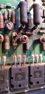
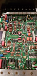
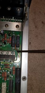
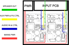
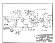
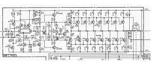
And now for the guts. The boards are very obviously quite different, but it does look like the tuner section is fairly similar. Maybe i can compare them to help find faults in mine? The new one does work in my truck, while the old still doesn't, Also note the date code, i assume, on the big chip at the bottom 95 48. Which is a bunch older than my 2001 truck. A big bunch. As far as i know its the original radio though. Original radio board with CD.

IMG_4069.jpg


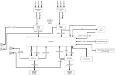
'New' radio without CD. Date code on its big, but different, chip is 94 52, so a fairly similar vintage. Also so darn clean. No idea what this is out of to be this clean.

IMG_4067.jpg


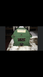
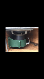
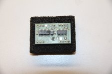
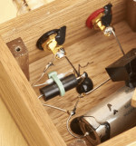
But the cans are probably the same. So yay? Maybe? Or do the supporting tuned thingies need tweaking to make it work so its basically hopeless? Original can.
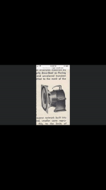
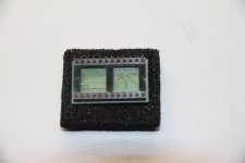
IMG_4070.jpg


'New' can.

IMG_4068.jpg


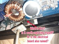
I have temporarily run out of knowledge though. I can do electronics to some extent, but i know nothing about voodoo, err radio. I do think that can has something to do with it. No idea if that is whats broken. So far testing voltages on the two boards seems close enough on all the pins of the cans that i would say it should work, if it works, or i'm not supposed to get voltage but something fancier and i don't have the tools to measure it.

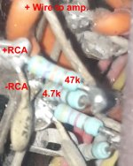
I did have another thought here as i got the very clean 'new' radio. I don't actually care about the CD player. Only wanted it for the bluetooth module to splice into and play silent CDs with phone music instead. This is how i had read others having done it, either with cassette or CD. Seemed like a fun project to 'modernize' without actually going for a ugly modern 'solution'. But, would it be simple to splice into the AM source instead, before the mux which i assume is somewhere (haven't really gone down this path yet) either breaking the traces from the AM source completely or putting in some switch that does it. Then i could have the 'new' radio play FM normally and hit the AM/FM button would swap to bluetooth. I assume the board doesn't care what the source is doing on the AM side unlike the cassette/CD side, where if it doesn't play it won't stay on that input.

Fun little project so far even though i haven't done much.

Driven Cascode Novelty Circuit

Following my experiments with the modular power amp https://www.diyaudio.com/community/threads/rcp130-modular-lateral-mosfet-power-amplifier.368795/ where I gathered knowledge regarding several types of input stages I finally chose the mirror loaded complementary symmetrical IPS described here: https://www.diyaudio.com/community/threads/slone-amp-final-solution.379346/

When using a symmetrical complementary IPS loaded with mirrors we face ourselves with the typical problem: “the VAS input voltage is not defined by any reference voltage, so it depends on the VAS base current and the Early voltage of each transistor connected to that node, as well as the common mode offset current of the LTP.”

To circumvent this problem, I added a 1k resistor (R12) between the emitters of the top CM (Q10) and VAS bjt (Q3). Fig 1

1661003027220.png

Fig 1 (R12 action)

According to Keantoken, R12 works actively by converting the VAS and CM into a CCS (analogous to the standard 2Q CCS).

As I see it, the current in the CM is perfectly defined and produces a voltage drop across R2 (Q10 emitter degeneration 133ohm).

R12 transfers this voltage to the emitter of the VAS Q3 so a fixed current runs through its degeneration resistor R11.

NOTE: R12 can not be replicated in the lower VAS (Q5) because that way both positive and negative VAS would try to fix a current in the bias spreader and due to differences in NPN PNP transistors, the current would never be exactly equal… (Both VAS currents would fight each other).

As is, R12 fixes the current on the positive VAS and the negative VAS just follows as if loaded by a CCS.


Another benefit from this configuration is that OLG is not severely decreased as in the case where both VAS currents are regulated.

Lowering R12 value increases VAS current stability but lowers OLG. The 1kohm was chosen because it represents a good compromise between current steadiness and High OLG.

1661003054617.png

Fig 2 (New circuit OLG plot)

-------------------------------------- NOVELTY DRIVEN CASCODE ------------------------------------

I chose to cascode the input jfets because when the cascode is “Driven with output signal” it does minimize voltage fluctuations between the sources and drains of these JFETS.

This “constant voltage” approach can effectively reduce higher order harmonic distortions.

In my prototype, the voltage divider that sets the cascode base voltage Fig 3 (R37 R45) is modulated by input signal through the connection CCSP…. While this method works, there is always a small current diverted from the Jfet sources to the voltage divider and Input Jfets Vds is not really constant.

1661003094391.png

Fig 3 (Prototype driven cascode circuit)

In my new design Fig 4 I chose to drive the cascode bases through a NFB replica coming from the output signal.

In this case the negative feedback replica circuit (R59 R60) modulates both positive (Q7 Q8) and negative (Q12 Q13) cascodes, through the bases of the followers (Q19 Q20).

This way, by carefully choosing R60 value (1k98 ohm) I can stabilize the voltage between the Drains and Sources of the IPS JFETs.


1661003168833.png

Fig 4 (New Cascode drive circuit)

Looking at Fig 5 I placed two test points: JD on the Drain and JS on the source of input jfet J1.

When running the simulation, we see that JD sits at 9.572V and JS at 98.6mV

Plotting V(jd)-9.572 and V(js)-98.6mV we see clearly that both curves are coincident and by tuning R60 we can actually null the difference.

Here we see 542uV Vds voltage variation @ 1KHz 290W.

1661003225191.png

Fig 5 (Input Jfet Vds plot)

Viewing the results of the .four command Fig 6 (1Khz 290W), we observe that THD is minimized when both curves are coincident.

1661003283971.png

Fig 6 (1KHz 390W FFT)

I hope this new method gathers enough interest to produce a fruitful discussion on how to best “drive” both cascodes simultaneously.
To facilitate analysis I am including and .ASC file that can be used for testing.

All models are included in the .ASC file so it runs directly in LTSPICE.

This simulation is initially set to produce 300W into a load of 5ohm @ 20KHz

You can choose other values by modifying the values of:

.param power=300

.param freq 20k

.param rload=5

Control transient is:

.tran 0 {{delay}+(20/freq)} {delay} {timestep}

DISCLAIMER:
The present schematic must not be used for commercial purposes.
This is can only to be used as a DIY project.

Attachments

  • Like
Reactions: astx

Primare A20 Amplifier Hum

Hi, I have an old Primare A20 that’s been working fine for many years. Recently it’s started to hum through the speakers. The noise sounds like ground hum and is there even with no inputs connected and doesn’t vary with the volume. The sound is the same through both channels. I’ve checked and all the ground connections are fine. Is there a particular component that could cause this issue?

2.5 way Line Array. Will a common enclosure emulate a falling Q with rising frequency?

I'm working on a line array design that will go behind an acoustically transparent projector screen. The original idea was to use six 6.5" drivers and six Neo8 planars. But modeling in WinISD, and test speakers showed more low-end drop off than I was hoping for. So now I am considering changing the design over to a 2.5-way design; running the six speakers directly behind the screen upto 550 Hz, and the speakers that would be behind or below the projector screen only upto 80 Hz; hoping that the omni nature of the lower frequencies will not give me horrible diffraction artifacts off the projector screen frame and any other gear that happens to be in front of the speaker.

I am leaning towards having all 12 of the 6.5" drivers share a common rear chamber tuned to Q=0.707. My thinking is that as the frequencies rise above 80 Hz that the effective Q of the enclosure will shrink (because the low frequency drivers will be 15 dB down above 200 Hz) - improving impulse response. Is this a bad idea? Do 2.5 way speakers need to have the low frequency driver(s) in their own enclosure for some reason?

For six of the 6.5" drivers:
Q 0.707 = 6627 in^3
Q 0.577 = 16,100 in ^3 Almost 3x the volume required!


CENTER 2.5 frame highlight.JPGCENTER 2.5 xSIM.JPGLine Array Fusion360.JPG

Beginning my DIY build, (2x) 2xNC500MP

First DIY amp build. Got four NC500MP modules, planning two put into a box: https://uk.farnell.com/metcase/m550...250mm/dp/1510826?CMP=e-email-sys-orderack-GLB (for a total of two boxes). Also planning to design a pcb (block diagram attached) to perform auto signal sense, and mute on startup, 12V IO. What do you think? Any tips of advice? Thanks.

Attachments

  • 2xnc500mp_block_diagram.png
    2xnc500mp_block_diagram.png
    946.4 KB · Views: 95
  • nc500mp_block_diagram-2xnc500mp.png
    nc500mp_block_diagram-2xnc500mp.png
    41.9 KB · Views: 95

Kyocera and Solen caps question

Wonder if anyone has come across this before, I just got one of these caps:
https://www.mouser.com/datasheet/2/40/ffve_ffvi-3162691.pdf
and it came with a dot marked by one of the terminals. Does anyone know if that indicates a preferential polarity, an outside foil or whatever? There is nothing written anywhere about it.
I noticed larger capacity Solen PP have a + indicator as well. Should that be taken as the preferential plus or high impedance side connection?
thanks!

Adcom GFP-750 Right Channel Issues

I'm working on an upgrade modification for this GFP-750 preamp. Once the cap portion of the upgrade was installed, I noticed I had no right channel when the unit was out of passive mode. I've checked components, traces, solder joints, and voltages. Some of the voltages are off on the right channel, but I can't figure out what is causing them to be off. Any help would be appreciated.
Screenshot_20230714_085202_Word.jpg
20230715_143610.jpg

For Sale Lowther PM2 - Brociner 4C Cabinet

This driver has a cone that appears to have been an available replacement cone as seen in the Harmon Kardon images as well as being an exclusive clone for Brociner speaker drivers. It is in very good condition. DCR is good but there is a slight cone rub. I inquired with Lowther about re-coning this and they quoted approximately 800 euros (before Brexit) for new cone, re magging of the motor, and an updated basket design. I’m on the east coast and can deliver within 200 miles of nyc. The cabinet is solid but cosmetically poor. I will provide any and all info within reason. Asking $3200.00.
Open to reasonable offers. I’m selling this driver, which I will likely never have enough money to buy ( I found this one)
due to financial calamity. BTW, I’ve been on EBay for 20years 100%. Handle is Shokujitsu.

Attachments

  • EEC70E6F-8318-42AB-AE68-0D95186281F6.png
    EEC70E6F-8318-42AB-AE68-0D95186281F6.png
    145.1 KB · Views: 214
  • C2A5D090-4BF9-4B07-B8C3-FFF8944B1937.png
    C2A5D090-4BF9-4B07-B8C3-FFF8944B1937.png
    360.5 KB · Views: 211
  • 8CAFBED5-52CD-4AC8-9ACA-AC92C3DA4E23.png
    8CAFBED5-52CD-4AC8-9ACA-AC92C3DA4E23.png
    74.2 KB · Views: 208
  • 294E0D44-5377-4071-9109-91B94E97FD66.png
    294E0D44-5377-4071-9109-91B94E97FD66.png
    98.7 KB · Views: 199
  • AA4CA65B-B6ED-477E-AD48-D72C449E5462.png
    AA4CA65B-B6ED-477E-AD48-D72C449E5462.png
    338.2 KB · Views: 202
  • 973C1531-C86F-4737-80AF-C218210FF50B.png
    973C1531-C86F-4737-80AF-C218210FF50B.png
    151.8 KB · Views: 213
  • 1A918E01-6243-4273-9A9B-264A83836181.png
    1A918E01-6243-4273-9A9B-264A83836181.png
    242.7 KB · Views: 202
  • 7ECD735E-BA0A-4CA9-AFFB-4FBF01440EA8.png
    7ECD735E-BA0A-4CA9-AFFB-4FBF01440EA8.png
    267.6 KB · Views: 224
  • 6F58B7CE-11FB-49C4-8820-70EF2D44135E.png
    6F58B7CE-11FB-49C4-8820-70EF2D44135E.png
    115 KB · Views: 219

Memphis Audio PR1X1000 CLASS D MONOBLOCK AMP PROTECT LIGHT WON'T GO AWAY!

So I have this Memphis car Audio PR 1 × 1000 class D monoblock amplifier that I got from a buddy of mine and as soon as I turn the amp on, the protect light turns on. But after checking on my wires making sure that they were connected correctly the weirdest thing happened, when I would reconnecting the blue remote turn on wire to the amplifier, the light is blue for a few seconds then turns red as soon as I tighten down The wire... So I pop the top cover off the amplifier to further inspect it, and noticed there's these metal plates with three prawns that are rusted/ burned up. What are these connections and is it repairable?

Attachments

  • photostudio_1689445887361.jpg
    photostudio_1689445887361.jpg
    314.1 KB · Views: 138

Eval1 remove sockets?

Considering eval1 for purifi amp, but it will have to fit with other amp modules for a 6 channel amplifier.
This will got into a custom case with speakon and xlr cutout.
I see the eval1 has solder pads for speaker output, so I don’t need to remove the jacks.
For the xlr, there is nothing indicated. Can I get the signal from wire soldered underneath the board or should I remove the xlr sockets to solder wires to my chassis sockets?
Thanks!

Threshold S/350e Refresh

Hi All… UK expat based here in Singapore.

This is actually my first post on diyAudio… so please forgive me if this is in the wrong section or if the attached pictures are too big... or even if this post is a little lengthy.

OK, I’ve been reading and gathering as much information as I’ve been able to first, prior to posting. This is having come across a Threshold S/350e power amp locally, for sale.

Due to the age of these amps, I know it’s de rigueur to replace the power filter caps, change the tantalum to an electrolytic cap on the FEB, check (de-solder) and/or replace any output transistors that may have failed and replace the carbon composite resistors due to drifting for something more appropriate… amongst others !

However, before I effectively go ahead and purchase this superb amp and “go to town” on it, I’m by no means an electronics “guru”, but I know enough to refresh these amps and perform upgrades etc. So, would appreciate as much feedback or suggestions as possible from others members on here… and perhaps, if the man himself, Mr. Pass, would be kind enough to provide some additional enlightenment.

The following is what I plan to do, so far…
  • Replace power filter caps; any recommended value… or is it just a case of the largest value, lowest ESR and highest ripple relative to correct voltage and physical size that will fit ?
  • Replace base emitter resistors with Dale NS Series (non-inductive) 1% 2.5w wire wound; any alternative type recommended ?
  • Replace (C7) 4.7uf tantalum with electrolytic; low ESR recommended or alternative type for stable and long life ?
  • Replace (C4) 220uf electrolytic; low ESR recommended or alternative type for stable and long life ?
  • Replace (R37) 6.2Ω 1w carbon composite; any alternative type recommended ?
  • Replace (T1) trim pot with multi-turn type for easier adjustment from top of amp; any thoughts on this ?
  • Replace (C7,C8,C9,C10) power supply pcb (small) electrolytics with low ESR types; any thoughts on this ?
  • Add bypass caps to power filter caps; any recommended value and type ?
  • Fit a soft start circuit; any recommended brand ?
Also…
  • I’ve read somewhere on the internet but it wasn’t explained how, the balanced input impedance can be raised from 600Ω to approximately 50kΩ; any thoughts on this ?
  • Replace (Q5) 2N5566 with IFN2N5566 I’ve read it is/can be beneficial to replace this JFET; any thoughts on this ?
  • I understand a matched pair of IFN2N5566’s is required for the above point; any thoughts on this ?
  • I’ve read about one member; kevd having significant trouble some time ago trying to bias his amp which eventually turned out to be an incorrect CNY17-4Z optocoupler instead of a CNY17-3. I understand the FEB on these amps have (U1,U3,U5) three (3) CNY17-4Z optocouplers; do all three (3) need to be replaced as per component list, or just U3 adjacent to the trim pot ?
  • I’ve seen pictures of the (C12) 0.15uf/400v replaced with a WIMA polypropylene; any thoughts on this ?
  • Considering the idea of replacing the rectifiers with pcb modules utilising SiC Schottky diodes mounted on heatsinks; any thoughts on this ?Based on experience working with PA systems, I know all too well in general it takes more “energy” or power to drive the LO end, compared to the MID’s and HI’s. So this is what I have in mind at the time of refreshing this amp; my plan is to keep this amp as standard and run it Class A/AB @ 150w per side for the moment. Then, if I purchase a second amp, reconfigure it to an SA/3.9e and run it Class A @ 60w per side for driving the MID’s and HI’s, while using the first amp and run it Class A/AB @ 150w per side for driving the LO’s… this is to allow for “headroom”.
Hopefully, the overall above configuration will be a good match for driving a pair of B&W N804’s @ 89dB, which are notoriously current hungry and a fairly difficult load to drive down to 3Ω.

Perhaps an additional thought to allow closer location of each amp to each speaker without having to cross any of the cables etc., a more intriguing or adventurous idea would be to create a pair of S/350e “hybrid power” amps, using the existing double bridge rectifiers in each amp.

Looking at the schematic, mount a second transformer in each amp with a centre tap (how would this work with both 31v & 50v taps ?) two split the power filter capacitors using a custom sourced pcb then reconfigure and bias one side to run in Class A/AB @ 150w for the LO’s and the other side to run in Class A @ 60w for the MID’s and HI’s… would anyone like to enlighten if this is doable somehow ?

Other suggestions or input is welcome and greatly appreciated.

TIA… Phil.

Attachments

  • FEB Schematic.jpg
    FEB Schematic.jpg
    317.1 KB · Views: 243
  • Component List.jpg
    Component List.jpg
    126.3 KB · Views: 228
  • Hybrid Power PS Schematic.jpg
    Hybrid Power PS Schematic.jpg
    313.6 KB · Views: 253

RFC PCB NAD 3020 inspired '1120' pre amp + hi level pre out

Hello everyone! I was wondering if you could help me out.

A while ago I took on the challenge to build myself a quad NAD 3020 power amp with an ESP 4 way crossover, and a NAD 1020 pre amp. Without tone section, but with the 1020/3120 high level pre-out. Which would make this a NAD 1120 if you like. I know I do 😉
Clone power amp and PSU PCB's I purchased from Scafas.
I also bought a Chinese clone of the pre amp, but I thought it would me more fun to make this myself.
And so it began...
This is the first time I am making a PCB. A challenging task I must say!
After a lot of time fiddling around with Circuitmaker I came up with something I think I'm happy with. One channel only for now.

I really don't know if it's any good. Could you shed your light on this design for me please?

  • I copied the circuits from the service manuals and more or less followed the original PCB layout
  • I took the original NAD3020 pre amp section (with the benign crosstalk error). Rail voltages +29,9V and - 25,6V
  • ripped out the tone section
  • added the 1020 hi level pre out. That one runs on +-20V.
  • and hooked them up together, using the rail voltage of the 3020.

Questions I have:
  • is it possible to increase rail voltage on the high level pre out from 20V to 30V without changing resistor values? (R5xx)
  • Could you check on the value of resistors R541 and R539? I think I might have muddled this up.

PCB version with and without Gnd plane added, for visibility tracks on back layer
Thanks a bunch!

Attachments

4066 replacement

The 4066 4PST analog switch is widely used in vintage audio gear, but is notoriously BAD, both in THD and on-resistance. Analog Devices has a new switch out that is vastly superior---the ADG6412. It DOES require an adapter board to drop it into the 14-pin DIP footprint of the 4066, but a clever fellow has made some available in this thread:
https://www.tapeheads.net/threads/adg6412-possible-new-4066-replacement.103635/

Op amp for Bose 901 equalizer series IV

Hi All!!

I am trying to have some fun with op amp swapping with an old bose 901 equalizer series IV. I also have a series III which is fully discrete. The series IV euqualizer came with LF353, pretty bad. I mounted machined socket so I could swap them. I then installed RC4558, bad highs, super harsh. I moved to TL072, improved things, smoother, but loss of volume. Changed to NE5532, getting better. Do you have any other suggestion to mount a "better" opamp? I included schematics of one channel.
Thank you!!
Screenshot_20230715-140032_Samsung Notes.jpg

My take on fake parts

Just went thru a huge post on the LM3886 and a few on the TDA7294 on fake chips. With batch numbers which are not legit.
This seems to perplex a lot of people. When I built my first TDA7294 amp. The chips I got blew up the second power was connected.
Not being able to find original chips I found some which was marked Made in Singapore.
These worked. They were pushed to the chips power limits and it did not fail.

So here is my take on fake parts.
They are what we call in India backdoor parts.
I first ran into this problem in 2002 when I launched my first Digital Ignition. Only to find people were selling digital Ignitions for 1/10th the price.
So a year was spent trying to solve this problem.
These units were all stamped just like the original factory units. As part of my investigation I even purchased a few and opened them up. To find they were legit.
Finally just as I was about to give up. The mystery was resolved for me. These back door parts are stolen. Either from inside the factory or while in transit from the factory to OEMs.
Theft of chips and electronic circuits is a multi million dollar industry. To avoid being tracked its a very common practice to file off batch numbers and just replace them with garbage.
The first guy in the chain got the parts for close to free. He then files off the batch number Prints something different on it. And then sells it to re-sellers for 1/10th the price. The re-seller than marks it up by 100-200% and sells it to the customer.

Just thought I would share this story. It fits perfectly with what we are seeing happening with fake transistors and parts.
In fact goto any whole sale market in any major city and you will see them taking delivery of large consignments with no paperwork.

This is rampant in countries like China and India. And in the USA on ebay.
Stolen parts go for about a cent on the dollar. When purchased from the first guy. The final re-seller makes about 100-300% margin.
When it comes to other parts like Caps. They have a time expiry date i.e. if they are not sold in x months after manufacture their values fall. And they are unfit for regular sales channels so these also get dumped for cheap on the market.
There are guys who rebrand a similar IC or a poor quality IC but the numbers are small.
If you want more info on this look into the stealing of ICs and the volumes that are stolen every year.
I have seen both types i.e. crappy / wrong products rebranded. And original items rebranded.
There are many legit chip companies that do this on the side.

Funny configuration on Phono in

Im trying to understand why the designer of this amp. Used these components on the Phono Input.
He has soldered the following components between the Phono in to ground.
To the positive pin he has soldered a 47K resistor. At the other end he has soldered a 4.7K resistor to ground.
Between the Positive and the negative he has a 3K3 ceramic cap. When I enter this up in the simulator it shows a drop of 10% in the input signal.
But there must be a reason for doing this. After looking at hundreds of Phono sections I do not see anybody else using this.
The 4.7K to ground seems rather low. Most other designs use 100K to ground.
Have included a pic.
Should I mod this or leave as is ?.

Attachments

  • phono-in.jpg
    phono-in.jpg
    189.8 KB · Views: 114

autoeq2camilladsp - Easy Headphone/IEM config creation for CamillaDSP with AutoEq and Crossfeed

Dear all,

I have been working on a little CLI tool which makes it easy to create a config for Henrik Enquist's amazing CamillaDSP.
I am mainly into headphone listening so I wanted to have a solution to quickly create a config with EQ correction data from Jaakko Pasanen's wonderful AutoEq and also add different crossfeed presets.
Maybe the tool is useful for someone here. That would be great!
Since CamillaDSP is more and more integrated in RaspberryPi based audio solutions like moOde the tool can also be handy in that use case.

This is it: https://github.com/Ebert-Hanke/autoeq2camilladsp

I am happy to hear what you think about it. Also if someone has more in depth knowledge on the specific DSP implementation of classic analogue crossfeeds I would be happy to hear it.
Thanks!

Cheers,
micha
  • Like
Reactions: fb and TNT

Goodmans Triaxiom 212c - missing a tweeter horn

I came across a Triaxiom 212c mounted in a diy enclosure. It was teamed with a Decca Kelly DK30R ribbon tweeter. The triaxiom is in pristine condition except it is missing the horn on the coaxial tweeter. The DK30R requires a new ribbon so I can understand why the enclosure only cost $20.

It seems the original owner had simply used the triaxiom as a woofer only and had removed the horn from the coaxial tweeter. The tweeter tests ok so I was hoping to find a junked triaxiom somewhere in order to buy the horn. If anyone is able to assist I would like to hear from them.

Want to get really good at audio repair?

I would highly recommend anyone with novice to intermediate repair skills to get Perry Babin’s repair tutorial. I’ve been doing car audio repairs for a few years now, but not having any formal training, I was pretty good at simple repairs, but nothing really deeper than blown outputs or bad switches.
I recently got an updated version of Mr. Babin’s tutorial and started to seriously study it. I had 2 amps (a JL Audio E6450 and a Power Acoustik TS1920 Plasma Sphere) that had been sitting for over a year with bad power supplies that I could not figure out. Within 2 hours of studying the power supply section in the tutorial, I fully understood how the P/S works, and how to test the driver IC. The very next day, I got into both amps, and found the problems on both amps within 30 minutes. Ordered the parts, got them today, and happy to report that BOTH amps are now working. If you are SERIOUS about learning how to fix amps, don’t hesitate to get his tutorial. He has a free website that will give you plenty of info and a basic amp repair tutorial. https://www.bcae1.com/
Check it out!

ICE3B0365J Troubleshooting (W200 Sub)

Hello all.

I am currently trying to troubleshoot and repair a W200 Sub as a personal project/learning and it seems to have gone a bit beyond my circuit knowledge having exhausted most of the obvious testing (attached images blue=tested, yellow=replaced). A repair had been attempted by a family member prior and some of the tracers damaged so I had to repair them first.
The board is a 104-A05426B00V-E and is an ICE3B0365J chip, and after finding the chip datasheet have gotten the following readings;

1.SoftS - Unreadable (fluctuating)
2.FB - 473mV
3.CS - 0
4.Drain - 330V
5.Drain - 330V
6.n.c. - 110mV (fuctuating)
7.VCC - 15V (fluctuating)
8.GND - 0

I vaguely understand what each pin is for, but I'm not sure what values I should be expecting in order to trace where any extra voltage is being lost, or being gained. I am assuming the Feedback voltage is too low so it is cycling restart, but I might be misunderstanding the datasheet. The transformer secondary is not receiving any voltage at all which I assume is due to the VCC not being stable.

Any insight into this would be very much appreciated.

Progress 1a.jpg
Progress 1b.jpg

How to adjust the Bias on Mark Levinson 27.5 amplifier?

I have newly aquired a used 27.5 and need to adjust the Bias on both channels .
I have the schemtics and some description of the circuits , I think it is R114 which does the bias adjustment but not sure what should be the voltage acrosss Emitter resistor points... in my previous ML29 amplifier it should be +26.4 millvolts

Thanks for any help!

Georg

For Sale Dipole Drivers for sale: Bohlender Graebener BG NEO3W, NEO8S, Acoustic Elegance AE DIPOLE 10, LO12

Dipole drivers for sale new, never used:

BG NEO3W planar: with shallow back cup (one pair has back cups removed, but included) 4 pairs available, $150/pair
BG NEO8S planar: double magnet high output version, 2 pairs available, $250/pair

AE Dipole 10: 2 pairs available, $600/pair
AE LO12 D8: 1 pair available, $650pair

add shipping from NY, USA

My Best DIY high end speakers finally finished - 6 month of hard work. Detailed build information

I constructed my best DIY high end Speakers using multiple constrained layer damping to build a woofer enclosure that is far superior, a audio muffler design for the midrange and unique dipole multi position tweeter. The speakers have a unique vintage but modern design and can be converted in a compact version with amazing sound.

Login to view embedded media

Nakamichi PA 7 questions

Here is the schematic of the PA 7 nakamichi amplifier
Noticed that the LTP doesn't get any feedback from the output
Can somebody explain why ?
can somebody comment that in terms of sound quality ???


After that there is couple of more questions ....
in basic terms and except the feedback thingy this shares similar principal of operation with the ESP design p68, at least for the output schem.
Now Rod in his article suggest this amplifier for sub woofer use since there some concideration about crossover distortion or poor freq response , even though it is clearly stated that he didnt notice anything while listening to the amp .
So i wonder if a similar problem applies for the PA7
Then again there is a bit of wierdnes in the design since the amount of outputs is pretty high for 60 V rails .... I understand that this apmplifier with that ammount of outputs will easily drive any load regardless of the speaker impedance .
In the PA7 i also notice fairly hi ballast resistors 1R that also is a question

Thank you very much

Attachments

  • PA7.png
    PA7.png
    122.1 KB · Views: 474

Custom DietPi OS For Raspberry Pi 4 Audio Streamer

Hello,

I started using Moode Audio a few years ago and was always blown away by the difference between a dedicated Pi Streamer (with moode at that time) and my normal desktop pc... this is also where my "audiophile" jorney kinda began, things in the OS and on the hardware seems to really to matter
And while Moode Audio is a kinda good out of the box expierence, it really lacks the ability to be customized (you can do it but updates could break things you changed for example and there is always a limit of how much you can do and stay combatible with existing things)

I also looked at Volumio... but it never apealed to me, specially since i also heard the worse SQ as many others people reported
SqueezeBox/PiCorePlayer also never really appealed to me but i actually never tried it, i just never was a fan of LMS since it looks and feels kinda outdated

I recently started using DietPi (after trying to run Arch Linux) and i think its one of the best OS bases for the Raspberry Pi 4, you stay completely in the official "Raspberry Pi OS" realm but with benefits that DietPi brings via minimalizing the OS and their scripts
I currently just use the DietPi OS to use the raspberry pi 4 as "Audio Gadget" and CamillaDSP to route the audio from usb input to the dac output (this also sounds better then going directly from PC to usb input of the dac, this way you can also use RPI4 hats and use the RPI4 as "DDC" for your PC, which will be one core feature of this custom os)

Soo... now to this thread, while it would be great to make a own streamer os image from the ground up and share it with others this is way out of my comfort zone, so what i actually wanna do here is document my journey of tweaking the dietpi os to my liking and needs, so other users may get inspired or even try to help build with me the perfect streamer OS

i wanna document each step so that it would be easy for others to actually replicate the exact OS im using (well and for me in case something goes wrong, haha)

So what goals do i actually have?
1. being able to use the raspberry pi 4 as DDC for your PC
2. use the raspberry pi 4 as standalone player (basicly what moode/volumio does) for possibly best quality (tho from my tests using the RPi4 as DDC isnt far off if not identical!)
including for example cd support and dlna support
3. keep the OS as minimalistic as possibly
4. try to find the best software for each "step" (for example one huge step up for me was using linear phase EQ inside EasyEffects instead of other IIR solutions like CamillaDSP)
5. tweak the OS itself for better SQ (for example underclocking the RPI4, maybe trying realtime kernels later and so on)

i did got some inspiration by "GentooPlayer" and one thing that really intrigues me is the script-server, it could be used to offer install scripts (and other things) of the software i use to make things way more userfriendly (install dietpi, install script server, get my config files and go from a nice web interface 🙂) this seems way less hassle then building a own OS image too i think

What you guys think about this? would some of you interested in such a custom OS ?

For Sale TDA1541A DAC D/A Converter NOS Module Replaces SAA7220B Filter

New TDA1541A DAC D/A Converter NOS (non-oversampling) module replaces SAA7220B filter and includes muting function for CD players.
$70 each plus shipping. PayPal only. 2 are available.

Sold "as-is" and no warranty is expressed or implied. No returns or refunds. Sells and ships to USA residents only.

Attachments

  • IMG_4657.JPG
    IMG_4657.JPG
    250.3 KB · Views: 166
  • IMG_4658.JPG
    IMG_4658.JPG
    220.8 KB · Views: 159

Any idea what this part is?

Hello evertone.

I am trying a copy of a simple Zobel network and can't seem to identify this component (the small white one in the picture) I assume it is a small value resistor, but I have never seen one like this before? It's secured to an Ohmite WH series 5W resistor. I have all the other components to hand so I am going to breadboard and see how it works at virtually no cost, but would love to know what the stange white component is.

Thanks!

Attachments

  • Screenshot 2023-07-11 at 10.32.38.png
    Screenshot 2023-07-11 at 10.32.38.png
    1.4 MB · Views: 194

How to Make a Code for R2A15218FP

HELLO........I HAVE A AUDIO PROCESSOR NAME:-R2A15218FP RENESAS AUDIO PROCESSOR--[8 CHANNEL ] AUDIO PROCESSOR.......ACTUALLY IT DOSENT HAVE ANY DATASHEET TO MAKE A CODE FOR THAT AUDIO PROCESSOR.......................................................IS IT POSSIBLE TO MAKE A CODE FOR ARDUINO..............................PLEASE I AM TRYING A LOT TO DO THAT PROJECT........I WANT HELP.........CAN YOU HELP ME...... AND I FOUND A LITTLE ABOUT FEAUTRES FOR THAT PROCESSOR DATASHEET
df2.PNG

The best sounding I2S wiring

I have spent quite a lot of time experimenting with several modes of i2s connection, grounding and wiring and here is the final conclusion that I came to:
I have experimented with the following 3 methods of connecting converter to DAC via i2s:
1. TTL with only one ground wire and 4 signal wires (data out, lrck out, bck out, clock in)
2. TTL with 4 ground wires running in parallel with 4 signal wires
3. RS-485 using flat ribbon cable
And soundwise the winner is #2. TTL with only 1 ground wire has sound that has a small amount of noise which makes it very hard to listen to for any continuous period of time.
RS-485 sounds better than TTL with one gound wire but it has a small amount of noise as well that is quite difficult to listen to for a long period of time.
Also I want to say that I conducted the following experiment with RS-485. I cut the flat ribbon cable into 4 balanced pairs whereby 1 balanced pair was used for each i2s signal (data out, lrck out, bck out, clock in) and then I twisted wires in every balanced pair. So in efect I got 4 twisted pairs for RS-485.
I was unpleasantly surprised because it turned out that 4 twisted pairs sound worst for RS-485 than just standard ribbon cable. Why is that so, I don't understand.
Another experiment that I conducted was wrapping each balanced pair in a copper tape and connecting all these copper tapes to the DAC's ground. This configuration produced very bad sound with some kind of distortions which are very difficult to listen to. Why is that so? I can't find any explanation in view of the fact that as far as I can see people like to use standard HDMI cables or custom made HDMI cables for balanced i2s and such cables are sold at very steep prices.
Could anyone explain this phenomenon?

  • Poll Poll
BTJ or JFET in the gain stage

BTJ or JFET in the gain stage

  • BTJ

    Votes: 4 66.7%
  • JFET

    Votes: 2 33.3%

I asked the GPT guy, but I don't trust him that much, as for several times it answers dubious or incorrect responses... And I think some topics are somehow biased.

So I wanted to know:
BTJ or JFET?
How accurate are its answer?

GPT:

JFETs in the Gain Stage:

  • High input impedance: JFETs typically have a very high input impedance, making them suitable for applications where a high input impedance is desired. This minimizes loading effects on preceding stages and helps maintain signal integrity.
  • Low noise: JFETs tend to exhibit lower noise characteristics compared to BJTs, making them advantageous in applications that require low noise performance, such as audio amplifiers.
  • Simple biasing: JFETs have simpler biasing requirements compared to BJTs, making them easier to implement in some cases.
  • Voltage-driven loads: JFETs have a higher output impedance compared to BJTs, which makes them more compatible with voltage-driven loads such as capacitive loads.
BJTs in the Gain Stage:

  • Higher current gain: BJTs typically have higher current gain (β) compared to JFETs. This higher gain can be advantageous in applications where higher amplification levels are required.
  • Lower output impedance: BJTs generally have a lower output impedance compared to JFETs, which can help drive low-impedance loads such as speakers more effectively.
  • Wide availability: BJTs are widely available and offer a wide range of options, making them suitable for various amplifier designs.
  • Cost-effective: BJTs are generally more cost-effective compared to JFETs, which can be a consideration in some designs.
In summary, JFETs are often preferred for their high input impedance, low noise characteristics, and suitability for voltage-driven loads. They are particularly beneficial in applications that require high input impedance and low noise performance. On the other hand, BJTs offer higher current gain, lower output impedance, and cost-effectiveness, making them suitable for applications that require higher amplification levels and driving low-impedance loads.

PPI Pro mos 50/Sedona/MTX Terminator MTA250 5 pin Molex plug sucks, any better solution for replacement?

This same plug is on the MTX Terminator 250. Made by PPI. I have one and love it and still use it in my vehicle, running 400 watts mono into two subs. THe issues the that amp and this one is that samn Molex connector for the speaker wire, etc. Is there now a better way to replace that? Mine is sporadic and i temporarily fixed it by putting a nickle squeezed in beside the plug and working so far )this put the needed pressure on the plug I guess.
What's the easiest way to replace this today? 5-way binding post? What will work?

s-l1600.jpg


s-l1600.jpg


s-l1600.jpg

Thiele Small Parameter like Focal Audiom 15AX from currently available

I am looking arround to low frequency transducers like Focal Audiom 15ax.
Especially the values for Vas (635 L) and Cms (the driver's mechanical compliance = reciprocal of stiffness, in m/N) so as Qms are exceptionell large and the resonance frequency f-res is very low (22,8 Hz). This value is by the use of cloth surround instead rubber very noteworthy and an indicator for a very low weight (mass) of the diaphragm (cone).
All this features saves an unparalleled combination of clean and tight bass so as a very low bass at the same time, if the camber volume is appropriate therefore.

Drivers with similar parameters that I know are the follow:
- Cabasse 55ND
Cabasse haut-parleur 55ND
- HKM XX-21
(formerly WESTRA/TESLA, see attachement)
- 2x McCauley 6258
McCauley.com : Products: Components > 6258: Specifications

Unfortunately the Cabasse 55ND is too expensive and the HKM XX-21 has to strong variations between the individual devices.
From the McCauley 6258 I use two pieces in one chamber. Unfortunately in the meantime very expensive in Europe (and amazingly not in United States), now twice as expensive than 14 years ago by German's old distributor "Sirius".

Which additional currently available bass drivers in this size have similar parameters (as close as possible to the Audiom 15ax for use in large cabinets, i. e. VAS between 500-800L, f-res. below 25 Hz and Qms above 10)?

Thank you for any hints.

Attachments

  • XX-21.pdf
    XX-21.pdf
    104.9 KB · Views: 252
  • Focal Audiom15AX Thiele-Small large Font.jpg
    Focal Audiom15AX Thiele-Small large Font.jpg
    246.1 KB · Views: 340
  • Focal Audiom15AX Thiele-Small.jpg
    Focal Audiom15AX Thiele-Small.jpg
    148 KB · Views: 341

Why PCB CAD appears to cloud and subscription?

Many a PCB cad appears to be going over to cloud and subscription, wonder why that is, Eagle comes to mind, going over to Fusion and a subscription being asked for, is this a good or a bad thing?

I've been using Labcenter and was looking for something a little better.... no wonder I couldn't find Eagle, kinda leaves their users in a lurch if they start asking for a monthly fee.... I myself would avoid Cloud based CAD like a plague so that means RS Design Spark and others is a no. no for me, what do other folks think here?

As time goes by my choices seems to dwindle.

Dave

For Sale 6" SB Acoustics and 2" Aurasound Tweeter for Pluto Speakers

Another project I will no longer pursue...I bought these drivers for a Pluto type Speaker years ago...

(2) Aurasound NSW2-326-8AT 2" Tweeters
(2) SB Acoustics SB16PFC25-08 6" Woofers

All never been used - removed from box for these pics.

Buy some PVC Pipe and you good to go...

How's $130 shipped for all CONUS?

Attachments

  • PXL_20230509_130352503[1].jpg
    PXL_20230509_130352503[1].jpg
    241.4 KB · Views: 123
  • PXL_20230509_130446874[1].jpg
    PXL_20230509_130446874[1].jpg
    284.8 KB · Views: 104

Hafler P2400 Transformer and Rectifier

Hey all,

Just gutted a Hafler P2400 for the chassis to make my second ESP P101 (sweet!)

So I have the transformer and original rectifier and plug. I do not remember the Rail voltages, but the Power supply caps were 75VDC, so around 65 - 70V rectified.

TT-XL280 is what it says on label, and I believe this transformer was used on quite a few amps...

I will find out exactly what the secondary windings are when I have an idle moment...

How's $60 + ship from Chicago sub?

Attachments

  • PXL_20211005_005143685.jpg
    PXL_20211005_005143685.jpg
    977.8 KB · Views: 312
  • PXL_20211005_005148256.jpg
    PXL_20211005_005148256.jpg
    833.6 KB · Views: 298
  • PXL_20211005_005156916.jpg
    PXL_20211005_005156916.jpg
    548.3 KB · Views: 293

First DIY ported sub need help with port

Hello all, I will attempt a ported sub after successfully building my first sealed sub.

My driver of choice is the Dayton Max X 10-inch. Link: https://www.daytonaudio.com/product...-high-excursion-dvc-subwoofer-2-ohms-per-coil

Power will be supplied via Crown XLS 1502.

I will build the box on Dayton's recommendations of 1.1 cubic feet with a tuning frequency of 28-29hz. Currently, I am having trouble figuring appropriate port configuration.

1687371316488.png


In WinISD port length is 36 inches when the port area is 4 inches tube, with 24m/s air velocity. Or 46 inches when its a 4 x 4 (16 inch) slot; however it's 46 inches in length. I would have to do a lot of folds just to get that to fit. Then my volume would shrink, so I would need an even bigger box than what Subbox Pro is suggesting.

1687371565720.png


Using sub box. pro my port is always outside the box. I input the driver as taking up 0.1ft3
1687371698734.png


The issue is the port is stupidly long, with a port velocity of 28 m/s, regardless if it's a slot port or a tube port. My use case is music, so I would like to keep this at a safe level and not have any amount of chuff or distortion, or audible noise. What Can I do to rectify this situation? I am not well-versed in how certain parameters affect others.

It almost seems that the subwoofer cannot be built due to the required port lengths. I have not even added any bracing yet. Is there a software that works better than box pro that is free so I can visualize it? Would be nice if Subox automatically increased my box size to keep the 1.1 interval volume.

Thank you in advance.

MX50 SE New Version ??

I just received a pair of MX50 SE complete boards. Al info and pictures I have found on the Net show the usual versions with 669 a 649 drivers. The pcb heatsink shows the 3 drivers.
The one I received has substituted 2 2sa1704's and a 2sc2803. Also, the emitter resistors are .1 ohm verses the usual.22 ohm. 5551 and 5401 are also replace the BC556 and BC546 in the drive stage. The 1704's and 2803 are mounted a bit differently than the 669 / 649 drivers indicating a slight change to the pcb. layout.
I'm just wondering if this is a latest version or older. What I received is not what was pictured in the Ebay listing.

With that said... I tested both boards with 36V DC rails and they both looked great up to clipping at about 55 wrms. They both ran cool with DC balance less than 5mv both channels.

I can't seem to find (on the net) a schematic indicating the use of the 2sa1704 or 2sc2803. I have included what I received and the usual suspects from Ebay.
Pic 2 is the pcb I received and Pic 3 is the Ebay listing.
Current Ebay Purchase.pngEbay Version purchased.JPGMX50 SE Ebay.jpgMX50-SE-2x100W-dual-channels-audio-power-amplifiers-board-circuit-schematic.jpg

  • Poll Poll
Moode vs Volumio vs RoPieeeXL for UPNP Tidal

What is the best sound quality for Tidal UPNP:

  • BubbleUPnP + Volumio

    Votes: 0 0.0%
  • Mconnect + Volumio

    Votes: 0 0.0%
  • Tidal Connect

    Votes: 1 33.3%
  • BubbleUPnP + Moode

    Votes: 1 33.3%
  • Mconnect + Moode

    Votes: 1 33.3%
  • BubbleUPnP + RoPieeeXL

    Votes: 0 0.0%
  • Mconnect + RoPieeeXL

    Votes: 0 0.0%
  • Something else

    Votes: 0 0.0%

What is the best sound quality for Tidal UPNP:
BubbleUPnP + Volumio
Mconnect + Volumio
Tidal Connect
BubbleUPnP + Moode
Mconnect + Moode
BubbleUPnP + RoPieeeXL
Mconnect + RoPieeeXL

Programable Active Analogue Crossover

Hi,

I've started to develop a programmable active analogue crossover. The board has an onboard PIC chip for easy programming via a Windows app / USB. The initial goal is to see if I can recreate the Linkwitz ASP in a programmable analogue form for the LX521 speakers. The signal path is completely differential analogue from in to out. No DSP in sight.

I am designing the board to use with 8 of the MOD86 amps by Tom/Neurochrome.
http://www.diyaudio.com/forums/vend...mposite-amplifier-achieving-0-0004-thd-n.html

So, I have made a start. I have started the schematic, chosen a few comps, and made a simple PCB layout.

Input - XLR differential (OPA1632) to 0-3v.
Output - 0-3v differential to differental / single ended (OPA1632&OPA1611)
Analogue and digital supplies - TPS7A47/33
Crossover ICs = special sauce.

I am looking at resitors and cap choices. I hear Susumu RG 0805s are the gotos for SMD. I will keep you updated over the course of the next few weeks.

Attachments

  • Rev1.0-Assembly.jpg
    Rev1.0-Assembly.jpg
    450.6 KB · Views: 597

Setting up a large PA system for a festival

Hi, I'm pretty new to all this concerning speakers.
I'm running a medium sized festival. I currently have 4x Peavey 215s for the tops and a pair of RCF 18 subs. I wanted to add an extra couple of subs. Would it be ok to add 2x Peavey UL215s to the mix?
I have two Behringher EP 4000 power amps.
I was gonna use one for the 4 subs. Would this be ok?

Sorry for being thick 😩😂

Thanks,
Ryan

3 way? Purifi PTT6.5 8ohm, Audiofrog GB25, Bliesma T25.

So I have these from trying to design a car system but I think I may just us the Dayton Reference drivers I have in my car.

Bliesma T25A and S
Audiofrog GB25
Purifi PTT6.5x 8 ohm

Thinking I could build a small powered pair of speakers. Also have a pair of SLS 6.5 if those make more since.

Should be able to design a speaker ending with a sensitivity of 82db a 1 watt that can handle around 100 rms 300 max. Think that's pretty good for the size but I may be off base, why I'm here.

Would any of you consider building this? Active or passive? Thanks for your time and thoughts.

Graham Holliman Velocity Coupled Infra Bass Speaker?

Has anyone here heard about the Graham Holliman Velocity-Coupled Infra-Bass Speaker? If is a very old design but a very efficient VERY low sub woofer box. I discovered the plans a while back and I dont know what driver to use. In the plans they say there is a LED circuit also to indicate the presence of infra bass activity (potentially dangerous!!). The crossover is also mentioned but the diagram of specifications are not given. I am trying to keep this as original as possible so if anyone has any of this information or has every heard of this design please let me know.
Thanks
Neopsp 🙂

My First Crossover, 2-Way w/ VituixCAD

This is my first attempt at designing a 2-way crossover and I don't know if I did it correctly. Please offer advice on errors or better crossover strategies. It isn't passive because I don't have proper testing equipment, passive components, or any experience working with passive crossovers. My intent is to put this crossover into Equalizer APO so I can see what it sounds like before trying to design a passive version.

I used VituixCAD but I didn't have an XLR mic with external sound card. I had to measure using a USB microphone and REW's "Use Acoustic Timing Reference" option. Measurements were taken outside on a 7 foot scaffolding with a 3 foot extension on a turntable = 10 feet total. The photos are vertical measurements, with the acoustic timing source to the right of the measured 2-way speaker.

This is a freestanding ATH waveguide speaker: 46 degree half angle, 8.7 inches (222mm) axisymmetric, B&C DE111 compression driver. Waveguide can be lowered and raised to adjust center to center distance. It can also be moved forward. At present, it is flush with the front of the woofer box which is a 9x9 inch (228 mm) O.D. cube with an 8 inch Dayton DC200-8 classic woofer. I cut off the low end output of the woofer just to prevent confusion from the lower frequency measurements. I'll eliminate the LF cutoff from the APO crossover and let the woofer naturally roll off to wherever it decides to go. Woofer box is closed, no port.

My design process was to 1) smooth both driver responses to 12 dB then use Optimizer "Axial Response of Driver" to create a transfer function file to flatten each driver, 2) add the amplifiers, and 2) add a 47uf capacitor in front of the tweeter as protection against accidentally sending full signal.
My REW measurements did not reach 80dB across all frequencies so I flattened them to 70dB then raised them to 80dB in the Drivers tab to make it easier to see the report results. I don't know if that was the right way to do it. Further, the woofer was measured at -10dB in REW and I reduced the tweeter to -20dB because the tweeter was way too loud to shoot around the neighborhood. Same amplifier level but lower dB in REW.

Please let me know if you see any red flags with my measurement and crossover process that destroyed any chance of getting a useful simulation from VituixCAD, thank you. I have included the VCAD files in a Zip folder. I can supply the original ungated REW file measurements if it will help. Also, I did not do a near field measurement/merge of the woofer because I was only interested in learning how to use the program. I don't know if that ruined the crossover design process. Thanks

555dc53afaeb6cd86ebc773118546340edf76ca9-1.jpegc1d3a309d2498ac0467c3f8d1387e0b82b851b9a-1.jpeg

Capture.JPG

Practice Power+DI.pngPractice SPL.png

Practice Directivity (hor).pngPractice Directivity (hor)_Line.pngPractice Directivity (hor)_waterfall.png

Practice Directivity (ver).pngPractice Directivity (ver, pos front)_Line.png

Attachments

  • Like
Reactions: profiguy and AllenB

Just finished my CSS Criton 2TD-X Towers...in solid mahogany

I’m excited that – finally! – I’ve completed my Criton 2TD-X Towers build. After I’d built a pair of 2TD-X MTM standmounts from the flatpack more than two years ago, I decided that I wanted to build the tower version, but I wanted to build them from solid hardwood as a “legacy” project. I spoke with a number of people about the challenges of building from solid wood rather than plywood or MDF, and people like Lou Hinkley of Daedalus Audio convinced me that it can work, as long as the right wood is used, along with good woodworking technique and appropriate bracing.

I settled on quartersawn African mahogany, which is a very stable species, and I recruited a skilled friend with an excellent wood shop to help.

Here’s a summary of what we did:

We used kiln-dried quartersawn African mahogany in sufficient board widths to avoid main panel glue-ups.

We planed and jointed all boards to ensure uniformity and good fits.

We cut box joints to join the tops and bottoms with the sides.

We mounted the back panel in a rabbet.

We installed a 18mm Baltic birch inner baffle in a dado behind the front mahogany baffle.

We glued and screwed the front mahogany baffle to the inner ply baffle, setting it in the recess between the side panels, tops, and bottoms.

We used 18mm Baltic birch for the interior braces

We routed a 2” radius roundover on the top, bottom, and side edges of the front baffle.

We lined the cabinet side walls with GR-Research’s No Rez foam.

We built the crossover from CSS' upgraded component list, with Erse Perfect Lay air core inductors, Mills resistors, and Jantzen Superior caps.

We used Neotech 22 AWG solid-core silver wire from the crossovers to the tweeters.

We used Neotech 16 AWG solid-core copper wire from the crossovers to the midwoofers.

We used Dayton Audio aluminum panels with cutouts for two pairs of binding posts, then installed a pair of Electra Cable tube connectors and a pair of high-quality gold-plated binding posts in each one, with the tube connectors and the binding posts jumpered together (the input wiring from the crossovers is Cardas 101 speaker cable directly into the tube connectors, which are the primary connection point).

We installed flanged screw inserts to accommodate IsoAcoustics Gaia II isolation feet (which sit on their spiked carpet disks).

We finished the cabinets in Odie’s Dark Oil and Odie’s Dark Wood Butter.

The reason I added both the Electra Cable tube connectors and the traditional binding posts to the input panel is that while my present cables are terminated with tube connectors, any other speaker cable I’m likely to use will probably have banana plugs or another more traditional connector, so I wanted to be able to accommodate them.

They've only been complete for about four days, but I'm very happy with the pristine, airy sound and precise imaging, together with an excellent low end. I’ve been enjoying high-end audio for nearly five decades, and these are the first speakers I’ve loved more than my original Martin Logan CLS electrostatics!

Speaker 11.jpg

Speaker 8.jpg

Speaker 9.jpg

Attachments

  • Speaker 11.jpg
    Speaker 11.jpg
    605.3 KB · Views: 197

LLC Resonant supply questions

I’m using one of these LLC resonant supplies in a tube amp I’m building. It provides

  • HT: 200V to 520V 300W maximum.
  • DC1 and DC2: 2.5V-6.5V adjustable 15W peak 7.5A.
  • DC3: fixed output 2.5V-15V, customizable, maximum 10W (not sure how it can be both fixed and customisable!)
  • DC4: -10V to -120V 50mA maximum
The Chinese to English translation “high power gallbladder switch” is very amusing.

My requirements are well within the supply’s specs even with a 50% derating and it bench tests fine with the loads I need.

I’ve read lots about LLC resonant supplies because they’re fascinating, I want to make some minor mods and I may need to make repairs or improvements if the supply proves unreliable.

I’ve reverse-engineered a schematic for everything but the controller which is on a daughter-board with an opaque coating. Based on all the application notes I’ve read I’m betting it has an L6599 on it.

I may have read lots but I’m still a hobbyist not an electronics engineer. So, I’m hoping someone can help me with some questions.

Each of the outputs looks like this:

1688970029847.png


What are the parallel resistor and capacitor from the negative terminals to chassis for?

All of the negative terminals will be connected to ground anyway shorting out the parallel resistor and capacitor.

The HT supply looks like this:

1688970042471.png


I’m guessing that as the output voltage changes the string of diodes (probably zeners) varies the voltages across the optocoupler diodes. The other side of the optocouplers disappears into the mystery controller board.

Why are there 2 optocouplers?

The specs state that the voltage is customisable between 220V and 520V. The jumpers are only giving me 400V, 410V or 420V. I specified 420V to the seller so that’s OK.

However, if I were to need some other voltage, what changes would be required? Swap out the zeners for ones with different voltages?

Finally, I was hoping to use the AC that becomes DC3 (supposed to be good for 50mA) straight off the secondary of the transformer. The requirement is only for 5mA or so.

1688970061348.png


1688970072939.png


When I try putting a 2k2 resistor or my planned load across the secondary, I get 0VAC and no DC3 output voltage. Any idea why that might be please?

Thanks, Dave.
  • Like
Reactions: exlabs

crossbar/crosspoint switches or IP Core to Quartus help

Hello guys of audio.
I'm trying to build an adaptation of freedsp Infinitas for Arduino Platform (Very probably Arduino Mkr Vidor 4000 because they have FPGA). The original project uses FPGA to do the crossbar switch and as interface brain.
I'm undecided if I'm going to stick with the original approach to this.
So let's talk about two different cases and the request for help applies to both.
First case: We are going to use Arduino Mkr Vidor 4000 and we are going to use FPGA.
Second case: We are not going to use FPGA.
In both cases Arduino will be the interface brain.
What recommendations can you give me? What free or very cheap IP Cores or physical crosspoint/crossbar switch (here doesn't matter price) can be used to achieve the goal and reccomdations to choose one?

Just to give an context here is the link of the projects freedsp and freedsp Infinitas:
https://github.com/freeDSP/freeDSP-INFINITAS
https://freedsp.github.io/

Half dead Sony TA-5650 options

Against my better judgment i purchased a TA-5650 on ebay. Predictably, half the VFETs are dead.

I'm pondering my options here...
  • since the 5605 has 4 devices per channel, would it be possible to modify it to run of a single pair per channel? Presumably this would mandate the use of a somewhat lower voltage in order not to overload the remaining devices. I'd then get a VFET amp somewhat equivilent to the 4650 that i could at least listen to.
  • Alternatively i could just sell the remaining good VFETs and recover my cost and either scrap the rest of the unit, or potentially modify to use standard MOSFETS just to avoid destroying a nice 70s amp if that is possible
  • And the last option... obtain more VFETS. I Don't suppose anyone has a set of 4 going spare? 😀


opinions/suggestions welcome

Back to the roots

Back to the roots

I started with audio electronics over 50 years ago. Now I have rediscovered my old hobby for retirement. I have worked in audio all my life as a sound engineer and production admin. Now I've got the soldering station out again. And it's a hell of a lot of fun. Most importantly, almost everything in components is available. Very different from 50 years ago behind the "iron curtain".
Am looking forward to many exciting projects.

P.S. "Bandit" refers to my motorcycle model
  • Like
Reactions: lene and cumbb

18 Sound 6ND430 + Seas DXT MTM + Hypex FA122

Hey guys, I'm planning on building some speakers for my home cinema and music listening setup, my proposed design is below. Im currently using Genelec 8030c's and love the sound but want more SPL. I have been searching a lot on this fourm and online and the 18Sound 6ND430 pops up a lot as an excellent mid-bass driver with highish sensitivity. I was orginally considering an MT version using the 4ohm version of the driver, but the 4ohm seems to perform worse than the 8 or the 16ohm versions and also appears to be OOS everywhere. I chose the Seas DXT for similar reasons to the woofer in that it seems to be a proven design and has been used countless times to great effect.

The design I propose is a slim, tall and fairly wide design. Reading online I can see lots of different comments about the DXT and baffle size, in that the DXT either likes a very narrow baffle or a wide baffle. My baffle is around 320mm wide by 572mm tall, with planned roundovers on all edges. My only concern is the performance of the DXT on this baffle, is it wide enough for this driver or would it be better to make the baffle as small as possible? I plan to cross-over around 2khz, how much of an issue will this present with the woofer C-C spacing?

Is this a good design for my requirements which are: Wide horizontal dispersion similar to the Genelecs, capable of reference level SPL (105DB) with great dynamics, flat on-axis and linear off axis response with a gently sloping power response, low distortion (both drivers show low distortion so should be no problem).

The cabinet will be sealed, as I see no reason to port given that a subwoofer will take over in the range of 80-120hz. The Hypex FA122 should give 125wrms into the parallel wired 8ohm drivers, modelling in WINISD shows around 110db in the sealed cab at the minimum 80hz cross-over frequency, which is in excess of the 105db requirement, so reference levels should be no problem.

What other drivers should I be considering for this project?

Attachments

  • MTM.png
    MTM.png
    13 KB · Views: 243

Ayon streamer - which OS runs their USB port?

Hi guys,

Do you know which OS and libraries run the Ayon streamers / transports?

I make USB DACs. I have recently been told that there is some issue with how Ayon's USB output port interacts with my DAC prototype.

I'd like to replicate the issue without having to shell out the full cost of an Ayon streamer. So if they use a specific version of, say, Linux and its audio core, perhaps that is something that can be installed on more standard hardware as well. .

Thanks,
Børge

A record-collecting book I think everyone should read...

Michael Fremer's "Tracking Angle" has put up Installment #3 of my ongoing series about great books about the history of records and of the record business.

3 Do Not Sell at Any Price.jpg

#3 is probably the highest recommendation I gave, Amanda Petrusich's Odyssey of collecting 78 rpm Blues records. I quote myself, under Fair Use:

START:

Supposedly, in order to sell a producer on your idea for a movie, you have to be able to explain the plot setup in no more than five words. One real-life example being, "Episcopal Priest Inherits Topless Bar." Really. The five-word movie pitch for Do Not Sell at Any Price might be "Rock Chick Hunts Blues 78rpms."

In the case of Amanda Petrusich, "hunt" is not a mere figure of speech. Ms. Petrusich was sucked so deeply into the vortex occupied by obsessive collectors of 78rpm Blues records (the title comes from a note she saw attached to one ultra-rare 78), that, despite her claustrophobia, she took scuba-diving lessons.

That was so that she could conduct her own underwater search of a river bed in Wisconsin. Why? Supposedly the P.O.'ed employees of Paramount Records, when the business shut down, had thrown the production stampers into the river. If that label name rings a bell, that might be because contemporary musician Jack White organized the reissue of most of the Paramount catalog in the famous "Paramount Suitcase" projects.

END

While you are at The Tracking Angle, please check out MF's review of the Meitner optical cartridge phono stage. Perhaps not so much for the phono stage, as MF's complete explanation of how the Microgrove LP encode-decode system (which "Turns Over" from Constant Amplitude to Constant Velocity) works.

That is what enables LPs simultaneously to encode a High E with a wavelength of 10 inches, and a Low E with a wavelength of 27 feet.

john

Question about the sound distance power and "throw" (?) for different subwoofer types

Hi everyone.

First, sorry for my probably poor english.

I'm currently designing a portable backpack speaker that has to be powerful enough for small outdoor parties. I already have the drivers and the mids and highs are already pre-calculated, i'll just have to adapt them to the design i choose.

I want to be able to have a strong output to the low 40 hz (F1 note above -3db is the way i design all my speakers, it sounds well for the type of electronic music i like to listen to) in the best db/size ratio.
I've already made some small portable BR boxes and a 12"TH (modified THAM design) trolley battery (<- low cost aliexpress) powered transportable speaker. I just wanted to simply design on software to get the solution for my new project, but there's something that i still don't know/understand.

When i tested the TH indoor, the output was obviously impressive compared to other designs i've listened to, but when testing outdoor, the difference seemed WAY bigger. The TH even sounded louder than indoor (?). And further from the speakers i went, bigger the difference between the BR and the TH was. It weirdly seemed to contradict the simple "-6db/2*distance" theory. I don't have the stuff to measure it (despite i'm designing speakers) so i don't have any number to show you (and it may even be just my ears making mistakes).

I've been looking for the explaination on various forums and few different explainations came.

1- "The size of the horn's mouth makes it different than a "point", so the 6db/2*distance rule doesn't apply until we get far enough"
- I doubt it applies for only a THAM12 sized mouth

2- "the horn makes the bass go "on the front of the speaker" without spreading everywhere so the sound power isn't wasted"
- I wonder why the difference isn't as big when i'm closer to the speaker then

3- "the sound 1m far from the speaker is 1m far from the sound source for the direct radiator and 1m+ the length of the horn for the sound source of the TH (sound source = driver for the TH). So if you measure 100db at 1m for both, you would measure 88db at 4m for the direct radiator and 94db for the TH if its horn is 2m long (100db was at 3m for its sound source, if you add 3m it doubles the distance so -6db)"
- This one is interesting and would make me build a second, smaller horn for my next project.

4- (do you know any other ?)

I also read about a 18"TH not making sound before a certain distance (15-20fts), which is what we would call "throw" (?), which means the sound just doesn't react the same way to the distance. I'd like to understand this one if it's true.


So in conclusion, do you know if there is a difference in the way the sound reacts to the distance depending on the design ? (i don't know if this question seems so english, sorry).

And more precisely, do you know what would sound the loudest oudtoor (between 3 and 8m far), a 93db/w/m BP6 or a 90db/w/m small TH ?

I already thank you if you took the time to read it.

Topping DM7 with Camilladsp (or other linux) crossover?

I've ordered a topping DM7 - an 8-way balanced output usb DAC - to replace my (deceased) 8-way soundcard; used as the output in a PC-based software crossover (for stereo 3-way speakers +subs). Whilst relatively low cost for such a device, it is quite expensive to me; a lot of unpleasant overtime working has been necessary to pay for it, so I hope that this was worthwhile.

Additionally, I'm also rebuilding my PC but this time intending to use Linux as standard. Camilladsp has appeared on my radar since last I went in this direction; it looks excellent and i would like to try it for the crossover (possibly more), though I haven't ruled out alternatives by any means.

The challenge may be hardware/software compatibility, and certainly my own lack of both linux and camilladsp expertise. But there appear to be precedents, such as this small post from tinnitus on ASR, suggesting that it might work as hoped. So I shall have a go, and would welcome thoughts and pointers from anyone who has done this or anything quite similar.

Cheers,
Kev

Mark Levinson 336 service manual & schematics

Hi everyone, new poster from Melbourne Australia here.

I have an old Mark Levinson 336 which has been in the family for a while now (over 15 years) getting recapped by a competent tech here in Australia. It had prior history being recapped once when I was still living in Singapore. During the recent re-cap there was some damage discovered on the left channel which the tech cleaned up and replaced the damaged cap & resistors (1st picture)

However on first power up 15 seconds in there was a pop and some white smoke which is obviously a bad sign. Luckily the damage isn’t severe, one of the circuit traces lifted (last picture). This is beyond just simple re-capping now and my tech is after the service manual & schematics to try and help me out. I’ve approached the local Mark Levinson importer but they are saying they do not support it as it is too old, and they do not have the service manual or schematics, only a service bulletin.

I’ve seen a few 336 repairs here so we thought we would reach out and ask if anyone has a copy of the service manual or schematics they are willing to share.

Thank you very much in advance.

Attachments

  • IMG_0237.jpeg
    IMG_0237.jpeg
    109.3 KB · Views: 373
  • IMG_0239.jpeg
    IMG_0239.jpeg
    159.6 KB · Views: 324
  • IMG_0238.jpeg
    IMG_0238.jpeg
    265.9 KB · Views: 308

Unusual opamp+buffer arrangement in the Monarchy Audio 22B DAC

For the 22B, there is an extra section of opamp+buffer for the output, which is based on a single channel opamp plus a LT1010. Interestingly, the input for the buffer is taken from pin 5 of the opamp (as opposite to the normal pin 6). As pin 5 is normally a NULL/OFFSET pin for certain VFB based opamp, wondering what's the purpose of using that pin as an output instead.

Note that the opamp's original part numbers are rubbed off, leaving just a small white square on the top right(near pin 5),so I couldn't identify the actual part numbers.

SBA 741 Crossover + MR13P

Hello all!

For sale the troels Gravesen's sba 741 crossover.

http://www.troelsgravesen.dk/SBA-741.htm

Crossover is built by me at the time when it was a free published project (now it is a closed design and only available from Jantzen)

All the parts are according to the schematic except the absence of the tank cap and resistor at the woofer because it made no audible difference when all the drivers were connected.

Woofer coil - 1.4 iron core Jantzen
Woofer cap - elecap

Midrange caps Jantzen crosscaps and standards
Midrange coil 1.4mm air core and 1.0 iron core

Tweeter cap - clarity cap SA
Tweeter coil - air coil Jantzen

The majority of the resistors are Jantzen superes and some few metal oxide.

Also a pair of satori mr13p-8 ohm is available for sale

Crossover - 150 euros
Mr13p-8 - 250 euros
Crossover+Mr13p-8 350 euros

Will ship from Greece, PP fees and Shipping are not included.

More reliable Upgrade for StBy Control Section in Yamaha's RX-N600 Receiver

Due a bad design in the st-by section always the same parts will be defective after a short time of use - go to the attachment and this video:
Login to view embedded media More URL's:
http://www.hifi-forum.de/viewthread-220-3803.html
http://www.hifi-forum.de/viewthread-46-16851.html
Are there companies, who offer upgrade kits concerning this stby unit for higher reliability ?
Thanks for an advice.


Owner's Manual is here:
https://de.yamaha.com/files/download/other_assets/6/327666/RX-N600_G_multi.pdf
Service-Manual :
https://elektrotanya.com/yamaha_rx-n600_eng.pdf/download.html
https://www.hifiengine.com/manual_library/yamaha/rx-n600.shtml

Attachments

  • yamaha-rx-n600-schematic-detail-standby-operation-4-pcb-capacitor-c3015-problem_655765.png
    yamaha-rx-n600-schematic-detail-standby-operation-4-pcb-capacitor-c3015-problem_655765.png
    54.2 KB · Views: 208

Radford STA-35 different versions

I've noticed there are at least 2 partially different amplifiers called the "STA-35 Renaissance", built by Woodside after Radford went bust (or sold the design?).
One model has ECC88 and the other has ECC81 and some other differences. I've also seen some having a toroidal power transormer.

The date on the bulletin of the ECC88 model seems to be '89 and the schematics of the ECC81 model are from '91.

Does anyone have any info on why the changes have been made?

Attachments

Lite Audio phono LS 37

Hi Guys. I'm looking for either the user manual or a wiring diagram.
This is the board: https://web.archive.org/web/20040614092825mp_/http://www.liteaudio.com/2003-5-15/2003515223145.htm
Besides wiring, I need to figure out what the dip switch settings are.
I've seen this post; but it tells only a setting for them, and now how to understand them

https://www.diyaudio.com/community/threads/ls-37-lite-audio-phono.129108/post-1600922

Projects by fanatics, for fanatics
Get answers and advice for everyone wanting to learn the art of audio.
Join the Community
507,771
Members
7,887,726
Messages

Filter

Forum Statistics

Threads
406,196
Messages
7,887,726
Members
507,771
Latest member
denengineer