For Sale JBL Ti2K/6K/10K Tweeters and midwoofers

EVERYTHING WAS SOLD

Hello.
Taken from som JBL Ti speakers tunned, for sale:

4 units JBL 806G-1 Midwoofers. Perfect condition. Outer diameter 190mm.


A pair of tweeters JBL Ti025k in good condition althoug some marks in the domes as can be seen in pictures. Outer diameter 100mm. They measure and play perfectly well. The domes can be swapped:
https://www.toutlehautparleur.com/diaphragme-audax-tw025a8-tw025a14-et-ti025k-4-ohm.html


If interested, PM me

10 MΩ piezo buffer pedal powered by DC adapter

Hi everyone, this is my very first thread.
My father and I are building a DIY piezo system to amplify my upright bass.
We've already made the pickup, now we need a buffer preamp because obviously if I plug the pickup straight to the input of my amp it sounds like absolute dog ****.
I've already tried googlin' some schematics, but I couldn't find any true solutions. I'd like to make it in a pedal format to include it in my pedal board for gigs and I'd also like it to be powered by a DC adapter rather than a 9V battery like all the designs I've found online. It'd be nice to have a HPF pot as well.
Thanks in advance for your help.

World class midbass horn

Selling a single midbass horn together with one Oberton 15NMB600 driver. Developed together with Bjørn Kolbrek (PhD in horn theory and author of "High Quality Horn Loudspeaker Systems: History, Theory and Design").

Measures very even and needs little EQ, and has a constant directivity of approximately 80x50° between 200 Hz and 1500 Hz.
The horn also avoids the floor bounce and measures therefore amazingly flat in the room.

A few pictures:
90 grader (Medium).JPG


45 grader (Medium).JPG


IMG_20190323_130121 (Medium).jpg


Dimensions:
Width: Max 122 cm
Height: Max 89 cm
Length with rear chamber: 120 cm

Rear chamber is built with a sandwich of two layers of birch plywood (2x 10mm or 12mm, can't remember exactly) with viscoelastic glue between and the horn with 21mm birch plywood. The rear chamber has a 2-pole speakon connector.

It's possible to buy a second midbass as well. However, the appearance will be different than this one and price will be higher. Or perhaps you can use this a center speaker.
Take note that shipment from Norway to the USA can be very high. Shipping to Europe is considerably less. Will need some time to pack.

Measurements here: https://www.soundlyvisual.com/index.php?threads/vera-audio-midbass-horn.35/

Asking price: 13000 NOK (approximately 1129 euro or $1206 plus freight cost. Or you can give a bid.

Contact: info@lydogakustikk.no

Will this SB20FRPC30-8 build make sense (in the future)?

Hi,

This is a 2 part question. I have a SB20FRPC30-8 full range driver and 2 SB20PFCR-00 passive radiators.
My plan is to build (will do calculations) a box which is slim (depth), but it could be made pretty large regarding height/width.

Because of the aesthetics, I want to do PR - FR - PR next to each other, vertically.
And also because of the depth there is no way to mount them on the sides.

Question 1: Are there cancelation problems if I mount these 3 in the positions I mentioned?

Question 2: Let's say in the future I hook (multiple of) these up to a 5.1 amplifier and cross them over at 80hz or 100hz, will the PRs still have their function or should I just go for sealed then?

Btw, I'm an absolute beginner. Know my way around making the cabinets with MDF but have not done anything more advanced regarding crossovers etc.

Thanks for your time!

TAOC Hi Fi Rack and Airforce V premiun

AISIN TAKAOKA CO., LTD. - TOAC HiFi Rack
Aisin Takaoka manufactures engine, brake, and automobile parts from a global production network of 24 companies in 7 countries around the world, using casting technology and plasticity technology. (Sister company of Sun Valley , owned by Toyota Motor Corporation (24.8%) · Toyota Industries (7.68%)


Two arm boards: SME V and SAEC + WT4700

LDR Attenuator Impressions

I recently constructed an LDR attenuator and volume control from Tortuga Audio. I was rather surprised and very impressed once I connected this up in my music system, replacing mono series resistor attenuators in each channel. The series resistor attenuator is a very purist connection between player output stage and amp input stage, a varied series of resistors and a switch contact. The music was good and I thought it would be hard to improve on.
I constructed the LDR unit mostly out of curiosity. I have read about them for years, but nevertheless a lot of things get talked up. But some times curiosity gets the best of everything.

Much to my surprise, I found that all the comments on LDR attenuators were not really exaggerating anything. The channel balance became more precise in that the music images became tighter and more focused from what already were tight and focused music images. Bass response was more pronounced and deeper. Dynamics were much more, as in the softs were softer and the louds were louder than before. The dynamics were the first thing I picked up on and then I began listening for other things.

Well that's all good and all, and then I immediately posted about the build here, trying to share my profound new enlightenment, as one is likely to do in such instances.

Now, I occassionally browse the threads about LDR attenuators and volume controls looking at what others have done, and reading all the arguments by those who think LDR's are all a bunch of rubbish and unfit for such an application and implementation such as this.
I really like the latter postings. It is clear from reading that the posters have no experience with LDR attenuators and volume controls. But the posters do seem to have profound knowledge about LDR's and why they are no good for this application.
But all the designers know the foibles of LDR's and their shortcomings. It's just that they know how to use them in an application for a specific purpose.
Theory be damned, it's the implementation that matters. And in the case of LDR's the implementations are really good.

For the curious or anyone wanting a simple project, constructing one of these is a real good use of time and money with benefits unforeseen.
While I went with Tortuga, there are other less expensive options. They all have their followers here.

Controlled Acoustic Bass System (CABS) to control room modes and decay time

I've been adding absorber panels to a room trying to damp reflections and the room decay time. This works and the results are in WideBand Absorber Panels however they are not practical for VLF (<125Hz) as the structures need to be very deep.

The "CABS" schema uses 2 source and 2 sink drivers in an attempt to suppress reflections and reduce the room mode decay times. CABS is described in :
A. Celestinos and S. Nielsen, “Controlled Acoustic Bass System (CABS)—A Method to Achieve Uniform Sound Field Distribution at Low Frequencies in Rectangular Rooms,” J. Audio Eng. Soc., vol. 56, pp. 915–931 (2008
Nov.).

Does anyone use this, and does it help ?

Matchless Spitfire OT Impedence

Hi,

I’m currently in the process of doing a Matchless Spitfire build. My concern is regarding the primary impedance of the OT. I’ve read through as many of the threads I could find on the subject but don’t thing I found a definitive answer.

I’ve read several times that part of the “Spitfire” sound is the 4k primary impedance of the OT that Matchless uses rather than the typical 8k for a pair of EL84’s. So I purchased a Hammond 1615A with a 5k primary and 4, 8, & 16R secondaries. According to other threads, this OT has been used by a few people for a Spitfire before.

My question is, do I use the 8R tap with an 8R cab? Or do I need to use the 4R tap with an 8R cab to have 10k on the primary? Not sure how Matchless might have had this setup.

Any help would be appreciated.

Thanks

Test OmniMic V2

I recently purchased an Omnimic V2 off of ebay and have been trying to measure a 3-way design to start my crossover build. In every measurement attempt on all drivers in my possession, a sine sweep shows the high frequencies are drastically reduced at around 9Khz (with almost no content above 10Khz). I'm trying to determine if the Omnimic is working properly or if there is something wrong with both my tweeter & midrange.

I downloaded the Omnimic calibration file, so that shouldn't be a problem. Does anyone know how to test this mic to ensure it's working properly?

Attachments

  • Tweeter.jpg
    Tweeter.jpg
    55.4 KB · Views: 137

Push-Pull transformer question

Hello,

I have a simple question about a push pull output transformer.

For example, when I go to Hammond, say one of their PP OPTs has "4000 Ohm ct" impedance on the primary side and 8 Ohm on the secondary side. My question is exactly where you get this 4 kOhm impedance on the primary side (assuming the secondary load is an 8 Ohm speaker). Is it plate to plate impedance (so that plate to center tap becomes 1 kOhm) or is it plate to center tap (so that plate to plate becomes 16 kOhm). Since plate-ct is the effective load to each tube, I am guessing that the transformer is 4 kOhm plate-ct (so you can directly use this value on a tube's load line) such that plate-plate is actually 16 kOhm, but I could not find a definite description...

Thanks!

Subwoofer hums when plugged in and connected to amp, even if amp is unplugged

The subwoofer in question is the built-in powered sub in one of my Vandersteen Quatro loudspeakers. The speaker takes four high-level inputs, two for tweeter/midrange and two for bass. The hum occurs if the power cord for the subwoofer amp is connected and either of the two bass section inputs is connected (could be positive, negative, or both). The hum is present if the source amplifier is on or off, and is present even if the source amplifier is unplugged!

Why would a hum occur if a single terminal is connected to an amplifier that isn't plugged in?

I've tried a ground lifer, no change. The other Quatro does not have this issue, and they are plugged in to the same outlet.

Amateur Amp Repair leads to an "airy" hum and purple/pink glow from a preamp tube...

Greetings friends. I'm attempting to repair a friend's Ampeg Jet J-12T amplifier and have run into the ditch. Take a look?

Here's the schematic. Amp was originally taken to the shop after it stopped working after a loud hum sound. Tech diagnosed a blown OPT but it was decided the repair wasn't worth the cost, so it came to me. As the amp was built in '96 it's time to replace all the EL caps, but all the WIMA film caps should still be in good shape. I was able to find replacement caps with similar specs for all except the preamp tube cathode bias caps; Mouser only had 22uF 35v caps of the Muse-UES type, which turned out to be Bi-Polar. Mistake?

I also found a broken spring in the reverb tank, and a damaged socket for one of the power tubes:
Login to view embedded media
After replacing the damaged socket and all the old caps, I put everything back together and installed a new reverb tank. I used a Variac and current-limiter and slowly brought up the voltage to full. After running for a few minutes I shut everything down, let the tubes cool off, and then plugged the amp right into the wall. Using my phone as an audio source I was getting a clean audio signal thru the amp, no hum. Volume, Tone, Tremolo and Reverb all working correctly, and the b+ was 320v, right in spec, As I was preparing to test and record all the voltages from test points, I heard a Pop, followed by an airy, fuzzy hum, and saw a purplish-pink glow inside the 2nd preamp tube. After a quick shutdown and cooling period I pulled that tube and saw a small crack coming from Pin 1. The getter of that tube is still mirror-shiny and it's been 24 hours since this happened, so it's not an air leak. Any ideas on what happened? Bad tube, bad circuit, or something else? Any suggestions, advice, help welcome.
thanks!

w

on wall or corner loudspeakers

I was building a music enjoyment room and it works well. The dimensions are around 4.5x6.1x3.2m and the room is constructed out of concrete, so quite quiet (even with an outdoor music venue close by) but to get control of reverb the largest surfaces are designed for sound absorption: the floor has a damped layer and the entire ceiling has microperforated sound panels with a layer of cotton insulation above it. Also most of the back wall is a bookshelf to act as a sound diffusor. So I am quite content with the acoustics of this room.

One restriction is the placement of my loudspeaker as there is a room opening to the hallway around 1m from the right corner so the distance of the speakers to the front wall is reduced in contrast to my previous listening rooms. Almost all speakers are designed to have enough distance from the wall in order to reduce the back wave and other early reflections to interfere with the primary sound or at least get enough time difference between the acoustic events.

On wall mounted speakers have no back radiation and that fact is used for a lot of monitoring or mastering rooms but not much for domestic listening. Obviously wall hang speakers require different parameters which may be too restrictive for commercial manufactures (with a few exceptions) but for DIY it should be more an opportunity than a restriction. I am thinking of a wedge shaped loudspeaker (25-30º) either close or direct at the corners. My present speaker design is vented but as on wall close to the corner room gain should be much more significant at 1/2 to 1/4 space so a closed box design may be better.

Playing with REW (which is restricted to .3m as a minimal distance to the the front wall) a distance of around .6m to side walls should work. One issue I try to find out are early reflections from the side walls (obviously no issue with front wall) with would reach the listening position between 1m and 1.8m from the corner so no issue at the hallway side (opening there) but on the left side. Would that be a significant issue? I was thinking one could design some sound baffles at the side of the loudspeakers even have a small gap between loud speakers and the side walls with some sound absorber stuffed behind. Maybe only beneficial for secondary reflected low frequencies but not too much early reflections. So I'm thinking of wedge shaped speakers direct in the corners (the easier design but no way to adjust the distance to side walls later) or just similar but smaller wedges close to the corners with or without some corner sound treatment.

Sennheiser/Grundig capsule wiring

Hey there,
I have two old Grundig dynamic mics (GDSM202) that as far as I understand employs a Sennheiser capsule.
One of those mics wasn't working and I ended up extracting the capsule from the housing. Now I wanna test it and can't really figure out how to wire it to an XLR.
PXL_20230914_050803578.jpg
If anybody can give me some guidance as for how to wire it the right way it'd be highly appreciated.

Thanks!

DML / Exciter Selection - Novel Project

Hey guys. I've finished building six sets of speakers using advice from this site - so a general thanks to everyone for sharing info!

I have a new project in mind, and after seven or eight hours of research I'm still not clear on what the key factors are in choosing appropriate exciters for a given size & density of material.

I'll keep my two questions short and sweet:

1. I have four 1/8" baltic birch artists panels mounted on pine (I think!) frames that are 3/4" thick and 1.5" deep (see image: https://www.canadaoncanvas.com/images/articles/wood_art_panel_front_back.jpg). Two frames are 20"x20", and the other two are 24"x24", and the plan is to use one of each size for the L channel, and the other two for the right. Any suggestions on what kind of specifications to look for, or any brand/model suggestions?

2. Is it totally crazy to attempt to mount multiple bass exciters on a solid core antique hardwood door instead of purchasing or building a conventional subwoofer? If there's a good chance that setup would produce some decent sound, any suggestions on type and quantity exciters for such a thing?

Sound quality is a much higher priority than budget. And I'd love to figure this out for myself if anyone has a decent resource - I'd definitely prefer to learn rather than mine you guys for suggestions. 🙂

Thanks so much!
Ash

List of current SMD audio transistors for preamp / discrete opamp

Dear forum.

I'm working on the "futile" project of a discrete opamp 😉

I'm looking for a good list of currently available SMD BJT transistors.

I was starting out with BC860C / BC850C, which overall I would guess is a good option, with low noise and good linearity.

I'm working on 3 stages; input, VAS/gain, and emitter follower/buffer.

I want to end with a design with relatively low overall distortion, but more important which is predominantly 2. order.

I'm pretty far with the design (LTSpice), but would like to tweak further, with choice of transistors in the different stages.

Input and VAS is PNP, buffer output is push pull NPN/PNP


Does anyone have a good short list to use?

Thanks 🙂

Connecting VU Meter to Audio Interface

Hello!

I am hoping there is someone who can assist me in this little fun project I'm working on.

So I'm taking a Behringer Uphoria UMC202HD and trying to add these VU Meters to meter each input directly.

The VU meters I'll be using are these cheap VU meters I found on Amazon.

Each input already has a signal/clip light so I figure I can just replace the two lights with VU Meters.

Obviously, it's not as easy as that. And honestly, if it came down to it I'd just be open to having it meter my main output instead.

Also another note, I'm pretty sure these VU Meters require 12v power and I'm almost curious if I can tap into the USB Bus power of the interface to get that or if I'll need a separate power supply.

Any and all advice would be much appreciated!!

Screenshot 2023-09-19 at 12.24.03 PM.png
Screenshot 2023-09-19 at 12.29.41 PM.png
Screenshot 2023-09-19 at 12.30.59 PM.png

Copland CTA405A - faulty resistor

Hello, I have a problem, the device works normally on the two channels, but when I measured the bias of the KT120
according to Copland procedure, on the first 3 valves it was approximately 0.47V, on the last right V203 valve it was approximately 5V,

clearly the trimmer does not have this range. I swapped two valves, but the problem remains on V203.

I tried to measure the impedance of the resistors in front of the trimmers of each valve with the digital multimeter, on three resistors R120-R119-R220 it was 10 Ohm, on the fourth R219 (always in correspondence with the V203 valve), the message " OL" value too large.

So is the resistor faulty? or could it depend on other components?

Can anyone tell me what type of resistance/impedance/tolerance is the R219? The colors on the resistor are not very clear.
Does anyone have schematics of the Copland 405A?

Thank you

Giustino

Some quick xover slope questions

Hey guys, wanting to experiment a bit with my active 3 way speaker driver integration. I'm currently running EQAPO and utilizing stacked filters to achieve what I believe is 12db, 2nd order high and low pass filters. This seems to give me good integration with in room response (can't measure outside due to equipment limitations).

My filter settings are quite basic, just picked some easy xover points, 300hz for woofer to mid, 2.5khz for mid to tweeter. I've attempted to utilize higher order filters but always run into dips at the xover points when utilizing the same xover points as the 2nd order filters. Am I correct in assuming that one would need to set the xover points for the drivers so the frequencies overlap? What I mean is that instead of 300hz LP and 300hz HP, I would have to something like 350hz LP and 250hz HP?

My current crossover does appear to give me good integration, I've attached an image. I'm just curious to test the benefits of higher order filters.

6LYYn2q.png

Newbie Questions: Arcade Speakers

Full Disclosure: I'm a mechanical engineer and know next to nothing about audio!

I've been tasked with specing an audio system for a racing arcade game we are designing.

The idea is to keep the speakers very close to the rider in the seat headrest like this: https://hunsakerusa.com/products/hunsaker-usa-gaming-chair-with-integrated-speaker-enclosures (but we will design our own seat)

The more localized the audio is to the rider without bleeding out to the spectators, the better.

The idea speaker size would be 3-4".

We definitely want a "premium sound" to it, but budget and long-term supply is a real concern as well.

I guess I will need an amp and a way to plug it into the micro PC onboard as well.

Any help would be very much appreciated!!

SemiSouth SJEP120R100 Single Ended Follower Amplifier, with Cascode and Choke Load

SemiSouth SJEP120R100 Single Ended Follower Amplifier, with Cascode and Choke Load

Always looking for a new diy project, I decided to do something with the two SJEP120R100 that I have. They started out in a diy stripboard version of a First Watt F2J. I really liked its sound, with its lower distortion, compared to the single ended SIT common source amps that I was listening to at the time. Now, I prefer the lower distortion level of common drain SIT amps, having built a few of them. So I decided to try a single ended SJEP120R100 follower amp.

The plan is to house it in a chassis that currently has two channels of a Sony 2SJ28 choke loaded follower. This chassis started out as a 2SJ28 choked loaded L'Amp (single ended choked loaded common source), and then FW F2J before its current iteration. The power supply is CLC, good for 23~24 VDC. The audio choke is Hammond 159ZC, 60mH, 0.7 Ohm DCR, and 2A DC current capacity.

So the plan is to make full use of the power supply voltage and choke current capacities. After some simulations, LTSpice showed that it may be possible for a choke loaded follower at 24V and 2A to output about 15W into 8 Ohm. However the dissipation may be pushing it a bit a around 45W, as the SJEP120R100 is a 114W device. To keep the same power output but with lower dissipation, I decided to add a cascode to the circuit.

The lower dissipation of the 2SJEP120R100 with the cascode in the circuit will also help in another way. When I had the F2J up and running, one of the 2SJEP120R100 had quite high gate leakage current. So running them with the higher dissipation would probably not work as the higher dissipation would increase the leakage current even more.

The schematic along with simulation results are shown below. The results are promising so the next step is to build the amplifier. Hopefully the amplifier will test as good as the simulated circuit.

Attachments

  • SJEP120R100 Follower LTSpice Sim.jpg
    SJEP120R100 Follower LTSpice Sim.jpg
    346.2 KB · Views: 578
  • SJEP120R100 Follower LTSpice Sim 1W Distortion.jpg
    SJEP120R100 Follower LTSpice Sim 1W Distortion.jpg
    244.7 KB · Views: 522
  • SJEP120R100 Follower LTSpice Sim 1W FFT.jpg
    SJEP120R100 Follower LTSpice Sim 1W FFT.jpg
    243.8 KB · Views: 236
  • SJEP120R100 Follower LTSpice Sim 10W Distortion.jpg
    SJEP120R100 Follower LTSpice Sim 10W Distortion.jpg
    240.7 KB · Views: 220
  • SJEP120R100 Follower LTSpice Sim 10W FFT.jpg
    SJEP120R100 Follower LTSpice Sim 10W FFT.jpg
    246.8 KB · Views: 188
  • SJEP120R100 Follower LTSpice Sim 15W Distortion.jpg
    SJEP120R100 Follower LTSpice Sim 15W Distortion.jpg
    245.8 KB · Views: 203
  • SJEP120R100 Follower LTSpice Sim 15W FFT.jpg
    SJEP120R100 Follower LTSpice Sim 15W FFT.jpg
    271.6 KB · Views: 507

LSA Signature 60 (AMT edition)

I have started on the development of a variation of the well-liked (and well reviewed) LSA Signature 50 speaker. It will have an AMT tweeter and an all new crossover and will be called the Signature 60.

Preliminary results are very promising.
121550F3-5F23-47A5-907D-F6EE504009BB.jpeg

Predicted response (blue) vs measured (yellow) response for the crossover. The crossover is my own passive (inverted) quasi-transient perfect Harsch. The hand drawn thick blue line is the tilt of the Harman House Curve” to give a slight down tilt of the response to eliminate listening fatigue. Crossover frequency is near 5.5kHz. I am listening to it and still voicing it. Sound is wonderful. Superb drum kit realism. Vocals midrange are to die for:
6D1B9A90-3AEA-4EEB-8FF3-9B659948CEAD.jpeg

Measured Step Response:
D43E81A1-C199-433E-A8D0-D7601C75BF0C.png

LSA Signature 50 Speaker

I designed the Signature 50 speaker for LSA quite a few months back but it’s finally starting to roll off the assembly line and will be shipping soon.

It’s a 6.5in 2-way bass reflex that uses a premium 28mm silk dome tweeter, and I gave details of some of the measurements earlier in the What’s on the Bench Tonight thread.

1651184609120.jpeg


Predicted response of crossover:
1651184640312.png


Step response is quasi transient perfect (inverted due to mic response):
1651184696835.png


1651184731020.jpeg

Custom crossover uses inverted passive Harsch topology of my design. All high quality parts like pure copper wire inductors, and custom made film caps and non inductive wire wound resistors:
1651184773136.jpeg


Impedance as function of frequency shows a true 8ohm speaker with lowest dip at 6.5 ohms above 20Hz:
1653054929878.jpeg


Here is the measured response (yellow) overlaid with the predicted response (blue) based on raw measurements from in-cabinet measurements of the drivers to account for driver offset and cabinet diffraction.

1679956299111.jpeg


And here is the measured harmonic distortion as a function of frequency - measured at 2.0Vrms and 0.5m:
1679956859254.png


You can listen to the first sound test here:
Login to view embedded media
First review is now in from Tone Audio:
https://www.tonepublications.com/review/the-lsa-signature-50-speakers-2/

Connect to passive sub

Here's a dumb question:

I've just built a passive sub with the Scanspeak 30W/4558T00. I'm using it with the TDAI 1120 from Lyngdorf and I'm using the onboard amplifier with a low pass filter of the Lyngdorf to drive the sub.

But how do I connect the speaker wire to the passive sub? Should I connect both left and right of both channels, or should I only connect one channel? I'm confused and I don't want to fry the driver...

Hope you guys can help🙂

Mads

Tube McCurdy help - phono pre AP 120

Hi Everyone,
I am restoring a McCurdy tube based radio station phono preamplifier unit. It consists of a pair of AP 120 phono preamp modules, AM 410 mixer / monitor amp and a PS 850 power supply. It's light blue in colour. It is mounted in the console with the turntable on top.

Working on it is tedious, wiring and components are tight. Does anyone have any technical information on the circuits at all? There isn't anything out there except the AU 300 phono preamp. That gives some clues as to how they thought at least. These pictures may ring a bell with someone (I hope).

This gets restored keeping as much to original components to retain the sound character. The carbon composition (new) I'm getting are all out of tolerance, so I'm not happy about that one bit. Modern caps though. Sorry, it has to be reliable.

Thanks for any help at all.

-Chris

Attachments

  • DSCN3228.JPG
    DSCN3228.JPG
    328.9 KB · Views: 76
  • DSCN4464.JPG
    DSCN4464.JPG
    453.8 KB · Views: 59

BC337 testing

hi everyone
firstly i'm an electronics noob
i just purchased a box of fake fairchild bc337-25 from ebay(not for a project just to tinker with), and was wondering how i could test them, so as to compare to the specs of genuine 337's. the fairchild datasheet only gives characteristics information, and no suggested circuits to test.
so far i can continuously draw about 400mA through one of the fakes, but at about 500mA the smoke comes out.

so basically my question is what easy tests can i perform to best compare the fake against the real specs ?

warm regards
gaz

QUAD 405-2 C2 polarized or bipolar cap?

I have several Quad 405-2 amplifier which I’ve done the usual recap on. I always go with the usual TL071 OPAmp. I have always followed DaDa electronics way of fitting a 100uF polarized capacitor instead of bipolar on C2. They fit the positive leg of the capacitor to ground. I myself usually use low leakage Nichicon UKL capacitors for this position. I recently just thought about if it’s is a good idea to use a Polarized cap instead of the bipolar that was fitted there originally. So, this morning I measured a couple of my 405s and saw roughly 0.2mV on both the negative and positive leg to ground, which seems fine. But what does the collective knowledge here say, should I replace the polarized with bipolar caps instead? Pic borrowed from DaDas 405 revision manual.

Attachments

  • C5E8D2A3-750C-43C7-8AAF-D2415F444D86.jpeg
    C5E8D2A3-750C-43C7-8AAF-D2415F444D86.jpeg
    385.8 KB · Views: 200

use and connexion a dac to a streamer and set up the hardware volume control.

HI
This is a question concerning the use and connexion a dac to a streamer and set up the hardware volume control.

My volumio is V3, My DAC SMSL M100 that is compliant with the hardware volume control.

When I connect the dac via the USB port I can set up in volumio the hardware volume control
When I connect the dac via Toslink, I cannot, only software volume control is proposed.

It that mean the hardware volume control only available if we connect the dac on usb ?
Did I miss something in the setting to allow the hardware volume control when connected via toslink ?

Help will be appreciated

Georges

Do Jantzen and Clarity caps mix well?

Hey recently I've been wandering if I can save some cash on a crossover upgrade by using a mixture of Jantzen standard z , clarity cap CSA with a cdet 940c bypass cap to meld them together. I need to make up a value of 7.5uf so would use 3.6uf standard and a 3.9uf CSA with a 0.01uf cdet 940c. Has anyone on here tried these two caps together in the tweeter circuit. Thoughts would be appreciated. The other components I'm using are Jantzen superes on everything but the parallel woofer spot were Im using Jantzen mox. There also is a parallel cap in the woofer which is an electrolytic so I plan to use a cheaper jantzen cross cap. The 1uf cap will be a Jantzen standard.
Attached is a crossover schematic

Attachments

  • IMG20230912225202.jpg
    IMG20230912225202.jpg
    203.1 KB · Views: 125

Scratching My Head w/ Crown CDi 4000

So I'll try to keep this brief. I have been trying to fix this amp that doesn't want to power on.. Yes I have read all the posts and seen the most common problem with this series is the cap 196 that is part of the start circuit. this was a design flaw from factory and changing it usually takes care of all the problems. No luck. What is making things the most difficult is that all the circuit is very small surface mount. It seems from measurements that I'm not getting the Kickstart signal that should occur with the SMP power supply. I'll attach schematic. Looking at page 6, power supply. All my measurements are referenced to V_BULKRTN. At power on I get ~168vdc across the main caps after the bridge. At TP31(C8) I get 0vdc. At the top of the resister divider feeding V_KSTART I have 168vdc and at the midpoint of resisters 84vdc. So testing the Zeners, D28, D29 in circuit both the 16v diodes test good .7vdc forward and open on reverse. The D25 tests good also in circuit. I also notice that I never get 30v_CTRL and thus no 15v_CTRL. That goes to alot of stuff. So that is a good start. One question where does the 30v_CTRL originate?? Is it the power transformer circuit at B6?? But that is the primary so not sure?
I have many years of repairing equipment but almost no experience with SMPS supplies. Understand just a little from Youtube. Anyway this is a very common problem with this line of Crown amps. But not the capacitor it usually is.

1694467983066.png 1694468040067.png

Attachments

Repair Klimo Kent power amp by my self

This pair mono mono power amp one channel suddenly humming loudly one day. Old amp so I try to repair by myself.
I unplug all tube and checked high voltage is AC 362V but DC is 445V, feel the voltage is too low (it must be 500V DC). So I think HV capacitor was broke down.
Original capacitor is Tesla 250uF 500V, its withstand voltage seems not enough, so I purchase KEMET ALC70 330uF 600V from Digikey and replaced it.
After running for a few days, the sound is getting better!
The following video is a record of my repair process:(Turn on English subtitles)
Klimo Kent tube power amplifier, repair by yourself - YouTube
AM-JKLWBBjQQU2nnKhcMrRo2U3C_DhP2I3M-DcjlGLMOqCJAXmVqLDpdG3H1_1sPwHcltPsmeUkxQqLTsFMFl-KAETsGXIhz77XoyuTDAhfoj9U6SC3tSq09BfDTORKeb63Kb8ETh1bXBNp1KgFKOLchz2YP=w1130-h848-no

Transformer specs and calculations not adding up?

Good Day All.

First post here, So, I took an existing toroid, It said 168va 30-0-30Vac I removed one of the windings completely and then rewound the other one, calculated I should be close to 12-0-12Vac, sure enough, I measured after the rewind and was sitting pretty at 12.2Vac per winding. This is where I am now left scratching my head.... If I take 12.2Vac x 1.41- 1.2V diode drop I get 16.02Vdc on the calculator, when I measure this with the meter at the caps I only get 15.48Vdc...... The rectifier is a repurposed RS1505m and I have 2 x 4700mfd @63V..... Does this sound right? I do not know so would rather ask.

Thanks in advance.
Regards
Charles

Fane 18XB 200l box design and modifications

Hi all,

I'm planning on building the Fane 18XB standard 200l design, found in the link below.

https://www.fane-international.com/downloads/Cabinets18inch200Lres.pdf

It'll be my first build and I'd like to make some slight modifications to the cabinet so it'll fit a little nicer with some other cabinets that I plan on building. I was trying to model it in in WinISD to help me with this but a I came across some strange numbers when modelling the original.

The actual plans state 4 ports of 108mm to obtain the tuning frq of 35hz whilst WinISD suggested the ports should be 310mm, slightly confusing... I'd rather go with Fane's designs as I'm sure they're tested I think but can someone explain whether I've missed something here or if it's just a quirk of the software?

Also is there anything that I should bare in mind about making the box slightly larger? Is it enough just to make the ports slightly shorter to keep the tuning frq the same relative to the increased volume?

Any help would be much appreciated.

Thanks!

Bipole sub with dipole speaker; asking for trouble?

I’d like to use a force cancelling (magnet to magnet) bipole sub to go “under” some dipole speakers I’m planning. I anticipate a low pass for the sub at about 80hz.
In order for the force cancelling to work the rear facing woofer will obviously need to be electronically in phase with the forward firing woofer. This means the rear wave of the sub will be out of phase with the rear wave of the rest of the speaker. Am I designing in a problem or are the wavelengths so long that its just a chaotic system at those frequencies and so entirely unpredictable ?

O2 headamp output booster PCB

O2 headphone amp output booster and upgrade PCB

EDITED and updated 1/21/2017. The latest V3.6 layout, schematic, BOM, part ID diagram and build instructions for this project are at a Google Drive link here:

https://drive.google.com/folderview?id=0B67cJELZW-i8Vmp5MDVLNzJxTGc&usp=sharing

Then the "V 3.6 1_28_2017" folder.

PC boards are available. To order a board see my vendor forum link: http://www.diyaudio.com/forums/vendors-bazaar/293309-agdr-audio-sales-thread.html

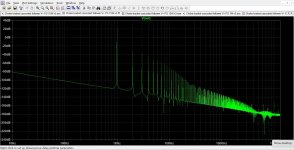
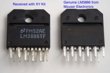
The final circuit uses the OPA140 or OPA827 (OPA827 is recommended) op-amps (FET input, DC precision, low THD+N) looped around an LME49600 audio current buffer on each channel to replace the O2 Headphone Amp's original NJM4556A output chips. The board produces a 93% reduction in the O2 amp's DC output offset voltage to around 20uV from the O2's standard 3.6mV, if using the recommended OPA827 chip. Output current capability is increased from 120mA per channel to 250mA for peaks - "music power" - playing music rather than sine wave testing. The O2's power supply has limitations that would prevent continuous current draw above 200mA per channel. The Booster Board adds: a headphone relay for zero turn-on or turn-off thumps; power rail reverse clamp diodes; and true zero ohm output impedance if the O2's 1R resistors are jumpered across.

PLEASE NOTE: I highly recommend using no higher than a 12Vac transformer with NwAvGuy's O2 headphone amplifier, givne the lack of heat sinks on the O2 voltage regulators. That goes for O2's with or without a Booster Board. You want at least a 12Vac 500mA transformer like a Jameco #101258. With the Booster Board the ideal transformer is the 12Vac 1amp (1000mA) Jameco #10081 for $1 more due. More than 1 amp wouldn't buy you anything additional.

There are several older versions of the board discussed in this thread, starting with the initial idea in the rest of this post below the asterisk line, leading up to the most recent V3.6. The project files for the older of these are under the "archived older versions" folder.

V3.5 changes

I corrected a bug in the older versions that caused the DC output offset to go up to O2 "regular" O2 headphone amp levels, around 3mV, when the volume pot was turned all the way down. The bug shouldn't have caused any audible problems for anyone since it only happened with the volume control rotated to the very extreme low position - no sound coming out. Now with V3.5 and above the DC output offset is the same ultra low 20uV even with the volume control down.

I moved the 1 meg ohm resistor that has previously been soldered in series with the sense wire that solders to the O2 board onto the Booster Board. The type of SMD diode for the relay was changed to 1A from the previous 3A, which was excessive. Placeholder pads (zero ohm resistors currently) have been added in series with the inputs to the LME49600, in case some other type of op-amps (other than the OPA827 or OPA140) require them. The RC power rail filters in series with the OPA827 power leads have their BOM values lowered from 100R to 1R. The previous value was set to coincide with the chip's datasheet PSRR drop. The new value sets the corner frequency at 72KHz, above the audio range.

The direction of the connection pins has been reversed from previous version in the build instructions, with the black plastic bar now up towards the Booster Board. The connection pins work fine either way, but one person using non-BOM IC sockets in their O2 had found that the pins fit best with the bar side up. I've also added wording in the build instructions to make sure the connection pins are centered top to bottom in the IC sockets if using the non-collet socket option in the O2 BOM, when soldering up the pins. The non-collet sockets have wide flat sockets for the IC pins which can allow 0.5mm or more of front to back placement. If the connection pins are not centered in the U3 and U4 sockets when soldering them they work perfectly fine, but one or both sets of will be at something like a slight 5 degree angle front-to-back.

The front panel green LEDs and their series resistors are now listed as "optional" in the BOM since most people have chosen not to install those. They have no circuit function other than just quick indicators to show the O2's power rails are OK (one LED on each power rail). They require two new small holes be drilled in the O2 front panel to see them, although the panel will clear just fine even without holes. Plus they cause a tiny amount of additional battery drain. There is a CAD file for a new O2 front panel with the LED holes at the Google Drive link above.

V3.5 was fabricated at a board house that allows the extra 2mm of board length needed to get all the connection pins onto the board, for the same price. Previous versions had the bottom two connection pins of U4 sticking out past the board (unused anyway) since the prior board house only allowed 50mm without a big price increase.

V3.6 changes

The left and right sides of the "tab" section are moved slightly, both 1mm to the left. This gives a little more room if a person has used non-BOM filter capacitors in their O2 which are slightly bigger diameter (one fellow ran into this with his Booster). Rectangular silk screen outlines have been added around the connection pin holes on the bottom of the board as a reminder to use the plastic-bar end of the pins up toward the Booster.

Placeholder pads added (currently un-populated) for bandwidth-adjust resistors for the LME49600 chips. The LME49600s are normally run in low-bandwidth mode (110MHz) since it is adequate for the OPA827 (or OPA140), pulls less idle current and produces less heat. But if someone has a situation where their specific headphones cause oscillation (very rare) the 100R bandwidth resistors can be added to bump the LME49600 up to high-bandwith 180MHz mode, for increased phase margin.

***************************************************************************


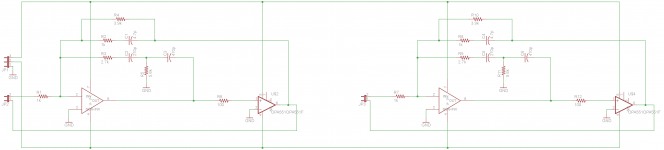
Sergey888 - I had an idea today for your OPA551 + linearization chip 2nd order circuit. 😀

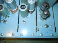
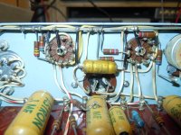
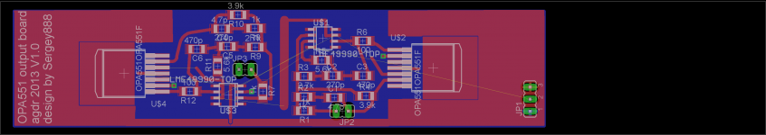
Turns out there is a open strip of space in RocketScientist / NwAvGuy's standard O2 headphone amp above all the front components that is 28mm deep and the 80mm case width. A circuit board slid into the top slot there clears all the components and mounts perfectly between the battery connectors in the rear and the front panel. The is 5.5mm of free space from the top of the PCB surface, inserted into that top slot, and the top of the standard B2-080 case.

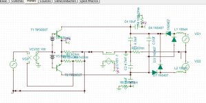
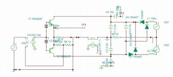
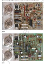
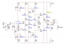
So here is your OPA551 circuit + linearization op amp layed out on a board that fits that space in the O2. I've left the area above the noisy AC input parts blank. The board connects to the O2 by using twisted pair wires going to DIP8 headers that plug into the IC sockets where the NJM4556A chips go. In other words, just pull out the two NJM4556A chips from the sockets, plug in the two headers like this one (Mouser #535-08-600-21)

08-600-21 Aries Electronics | Mouser

slip the board into the O2 B2-080 stop slot and away it goes! Well almost. One twisted pair of wires go to one NJM4556A socket header plug (input/output, signals in phase), 4 to the other (V+, V-, input/output signals in phase) but then one additional wire has to be soldered to a ground point such as the middle hole of the output jack connector. There is no ground present in the NJM4556A chip holes.

A few potential benefits of the OPA551 output chips vs. the NJM4556A chips:

* Potentially lower distortion given the loop with the LME49990 chip. I substituted the LME49990 for the LME49860 since no voltage higher than +/-15Vdc rails is needed anymore and the 49990 specs beat the LME49720/49860 slightly.
* One single OPA551 vs. the two paralleled sections of the NJM4556A on each channel. No paralleled outputs anymore. The 1R output resistors are no longer needed, no output resistors at all in fact, unless I run into reactive load oscillation issues during testing.
* Higher output voltage capability by 3Vdc peak! The 12Vdc voltage regulators in the O2 can be replaced with 15Vdc regulators (LM7815 / LM7915) and with a 16Vac or 18Vac input you now have +/-15Vdc rails. 😀 Looking through the voltage specs of RocketScientist's capacitors I think that I only saw one that has to be bumped up to a higher voltage. The LME49990 is not only specified at +/15Vdc, it is specified at 18Vdc. The OPA551 is good with either rail voltage too, of course. The existing +/-12Vdc regulators in the O2 can still be used too, of course. No requirement to go with a higher rail voltage.
* More power dissipation. I pitched RocketScientist once on bumping up the rail voltages to +/-15Vdc. He correctly noted that would push the NJM4556A's over their maximum power dissipation under some circumstances. No such problem with the DPAK OPA551's.
* It all fits, I think. The OPA551 is apparently 4.5mm thick and there is 5.5mm of free space above the board. We'll see what happens when it is soldered down with the solder film thickness. I've used 1206 surface mount for everything else.
* Short circuit protection form the TRS is maintained with the (short circuit protected) OPA551.
* Potentially higher current output. The OPA551's are good for 200mA each vs. about 120mA for the paralled NJM4556As, but I'll have to do some power dissipation calculations on the heatsink foil area and on the un-heatsinked regulators in the O2.
* Still battery power friendly for portable use! The quiescent current draw of the OPA551 at 8mA is about the same as the 9mA of the NJM4556A's they replace on each channel, a wash. So the added current draw from the batteries are just the LME49990's on each channel at 8mA each.
* Noise, or lack of it, may be about the same. 14nV/sqrt(Hz) for the OPA551 vs. the RMS sum of 10nV/sqrt(Hz) for the two parallel sections of the NJM4556A, which happens to also equal 14nV/Hz. The distribution over the higher frequencies is not the same though and the tiny 0.9nV/sqrt(Hz) of the LME49990 is added plus some additional resistor Johnson noise.

A lot more layout work to do, plus I need to add the bypassing. But it looks like it all may fit.

Attachments

Help modelling subwoofer?

Hey Folks,
I would do this myself but I don't have access to a windows computer right now and I need to make a decision in the next day or so.
I'm looking at the RSS315HE-22 dayton subwoofer.
https://www.daytonaudio.com/images/resources/295-291--dayton-audio-rss315he-22-spec-sheet.pdf

I've tried having a play with hornresp (I actually managed to make it work on my mac), but have had no luck with WINISD.
It looks like a very small sealed box, ~25L gives a Q= .7, but it reaches max displacement really quickly.
My biggest issue is that I don't know how to model a bass boost for a sealed system in hornresp.
I've tried playing with a ported box, and ~80-90L gives a good response, but the port ends up being very very long to reduce port velocity below 17m/s.

Could someone have a quick bash at modelling this and seeing what an optimal design would look like?
I tried searching on the forums for previous modelling and didn't find much if any!
I'm looking for <100L Box with decent response down to 20hz.
I know I'll need a heap of wattage to make this happen. A 105dB Max output would be perfectly acceptable for me.
A small(ish) box is the main priority.
I will have DSP available.

Thanks for your time, even if it was just giving this a quick read.
Thanks!

Yamaha CR-2020 Tr714 low ohms

hi there, first time posting.

i have a yamaha cr 2020 that was working fine, and just stopping clicking the relay and no sound.

its been recapped, and the service buillitens done. it has 2sd525 replacements.

on TR 714 i have 99 ohms and 0.068 in diode mode, reading between base and emitter. is this normal?

i was thinking this was my problem, but i dont know enough to be sure.

i have plus and -59 volts, but i dont know what else to look for voltage rail wise. any help would be much appriceated.

Help! My friend bought a cube

Friend of mine bought this house and this is the ONLY room available to set up as his listening room.

Not exactly a cube but room measures 17'4" x 18'3" with a 9' ceiling. Everyone knows a square room is terrible, but I've quickly learned that a square room where the ceiling height is a multiple is super extra terrible bad.

Initial setup was listening position 38% off back wall, JBL 4435's about 3' from each sidewall which put them almost right up against the main wall when doing an equal lateral triangle. There's no bass, tried multiple speakers with the exact same listening position, JBL L-300, Infinity Quantum 2's, Polk SDA 2.3 TL's, and many more, all speakers that should be able to knock a listener back in this room. Multiple amp's and preamps. The room has no bass, its like there's a crossover at 125hz or so, just nothing below that.

So my friend and I are on a wonderful journey together learning about room nodes! Yay!

My question to you all, if anyone here has any insight, can this be trapped/treated or DSPed out?

DSP would be an adventure, I'm going to try and teach him how to use a UMIK and REW soon, but I'm not great at it myself.

Another friend says lowering the ceiling by a foot and heavy corner and reflection point treatments are the only answer. The owner really doesn't want to have to lower the ceiling, and definitely isn't moving any walls.

Can it be fixed without changing the dimensions of the room?

Schematic for Focal FPP4100 4 Channel Amplifier.

Hello folks, working on this amplifier which blew one side of the P/S FETs (Q53,Q54,Q55). I replaced them along with burnt gate resistors. The replacements are getting hot very quickly so I suspect a bad PNP driver transistor. I’m having a problem locating that transistor and was hoping a schematic could help be locate it’s designation (Q01, Q02, Q21…).
I found some schematics online for other Focal amps, but none appear similar to this one.
Thanks in advance to anyone who can provide me with a scematic.

Attachments

  • F1FF3C20-7D70-494C-95F3-172F40B5FD65.jpeg
    F1FF3C20-7D70-494C-95F3-172F40B5FD65.jpeg
    747 KB · Views: 219
  • B3923192-F722-4A6C-B8C4-C9F020032F29.jpeg
    B3923192-F722-4A6C-B8C4-C9F020032F29.jpeg
    507.7 KB · Views: 186
  • 95DA57F2-C094-4055-9F84-30EDC438BB52.jpeg
    95DA57F2-C094-4055-9F84-30EDC438BB52.jpeg
    747 KB · Views: 392
  • 38A73A54-9F1F-47AC-8C52-217A1F2BC137.jpeg
    38A73A54-9F1F-47AC-8C52-217A1F2BC137.jpeg
    507.7 KB · Views: 253

Navigating the world of amplifier modules for reliable performance at 500-1000w at 8R

Hi all,

I would appreciate guidance for searching the world of Class D amplifiers, looking at a pair of amplifier modules / power supplies that can fulfil the following:

  • 500-1000W @ 8R
  • Subwoofer duty only
  • Reliable
  • Affordable


Can anyone recommend which of the 'Aliexpress' modules (or otherwise) can meet these? I have been burnt before by modules failing under load or just proving generally unreliable. I have been looking mainly at the IRS2092s and the UCD clones that seem to be all over there. I would ideally spring for something like two Hypex FA252 (it's for two active subwoofers), but they would blow the budget out of the water!

Many thanks in advance.

Wideband Multilayer Absorber Panel

I'm interested in hearing how my speaker's sound changes when the room reflections are more controlled. I see lots of thin single material panels however I think I would prefer a wide band multilayer absorber to uniformly reduce reflections and not disturb the spectrum profile too much.

I found a some material tables Material Tables and a multilayer calculator Acoustic Modelling that both seem reasonable. I have (arbitrarily) limited the panel depth to 20cm. I'll post the design with measurements before/after.

If you've built one, I'd like to hear your experience / impression.

Panels Built and room measured:
1) Standing panel (H183 x W61 x D20 cm) - Standing Panel
2) Helmholtz panel (H183 x W61 x D20 cm) - Helmholtz Panel
3) Wall panel RockWool (H122 x W61 x D80 cm) - Wall Panel - RockWool
4) Wall panel foam pyramids ( 91H x W61 x D5 ) - Wall Panel - Foam Pyramids
  • Like
Reactions: Dave Zan

Maximum typical slew rates in audio

I came across a topic yesterday that had me thinking about the slew rates present in audio and the max/min required for processing equipment - specifically, how to fill in the blanks in the following statement:

The highest slew rates are in the vicinity of <slew rate> and are frequently found in the waveforms generated by <instrument/voice/etc>.

My first guess (admittedly a WAG) would be the initial hard strike of a cymbal or something along those lines. Does anyone have any specific numbers and/or references on this topic?

Thanks,

Hal
  • Like
Reactions: kd4ylq

Which through-hole resistors for JBL VRX932LAP?

Hello everyone,

I'm working on several of these Class D amplifiers for a friend and have a question.

These are very similar to the JBL EON 515 by the way; they look exactly the same.

Here is the question though. I've gathered all the necessary replacement parts from DigiKey & Mouser but there is one piece of the puzzle which is still a mystery to me.

What specific type of through-hole resistors are these?

From the color bands, one is 24KΩ and the other one is 75KΩ.

I ordered some metal oxide replacements from the stores mentioned above but my worry is that the replacements are much smaller in size and won't be able to handle the load. Someone mentioned these could be "flame proof" elsewhere but I cannot find exact matches anywhere.

If anyone has any input I'd highly appreciate the feedback.

PXL_20230907_150833157.jpg

Supertweeter-assisted full-range & phase coherency

So when crossing a "supertweeter" (or just a very high-extension tweeter, no matter the nomenclature) over with a full-range driver with a single low value cap to really flesh out the topmost octave, is phase aligning them important at those nearing 20kHz and above frequencies?
I mean, as critical as phase alignment can be with a range of frequencies.

If I use capacitors as 1st order for the full-range anyway, are the drivers now phase coherent in terms of at least the signal itself? Would they not be if the full-range was ran entirely crossover-free?
In relation to this, how important is physical time-alignment?

Huge Thank you to contributors on this forum - Peavey 1.3K alive again.

Good evening all,

This is my first post here and my first amplifier repair. If it weren't for the details I found here on DIY Audio I would have missed critical bad parts and probably found them the hardest way by damaging new parts.

I revived my old Peavey 1.3k that has been sitting in a failed state for nearly a decade. I found that it failed big time as they tend to do it seems. I found and replaced nearly 55 parts across the drive and output boards. I have a bit more work to do on it, I have a few more electrolytic caps that I am going to replace just due to age but I did a low power test and found that I have clean audio on both and channels.

As I found discussed here, I am going to install an accessory fuse block to add fuses between the rectifiers and the output board to ideally prevent so much damage should an output transistor fail again.

Thank you to the contributors in this thread:

https://www.diyaudio.com/community/threads/peavey-pv-1-3k-power-amp-repair-question.271480/

Can a JBL 2225h really become a 100% 2235h?

I have spent the past few days searching this topic and I kinda hit a wall of contradictions.

For sure the JBL 2225h and 2235h have the exact same basket, and therefore a 2235h recone kit on a 2225h should make it a 2235h. Some will say the 2255h becomes a 100% exact 2235h. While others will say that the 4" motor is slightly different, and that therefore it will not become a perfect equivalent.

So... What's the last word on the subject? The topic is not about if a 2235h is or ain't a good sub. It's about the recone process.

Thanks in advance.

Audio Innovations Alto AM1 and CD Tuner CT1 remote

Hello,

I own an Audio Innovations Alto System, but without the remote control. Due to the design of this system, it cannot be controlled without the remote.

I am using a Logitech Harmony universal remote. Despite the system is in the database, there are important "missing buttons" and it's not possible to control the tuner functions. Only the "BAND" button is offered by Logitech.

Using an Arduino and a IR transmitter board, I have found some additional RC5 codes and now it's possible to control the tuner:

SCAN UP - RC5 code 0x45E
SCAN DOWN - RC5 code 0x45F

STORE radio presets - RC5 0x459

The Logitech Harmony can learn these codes and add them to the remote. Maybe this information can be useful for another Audio Innovations users without a remote or with a dead remote.

I have not found the PROG button code for the CD Player. I looks the remote uses also NEC codes for CD player functions. My Arduino reports the system code 0x21B2 and different codes for the PLAY, PAUSE, etc. keys

Best regards

Attachments

  • _DSC8145.jpg
    _DSC8145.jpg
    331.3 KB · Views: 590

18Sound 18NLS4000

Hi, as the title suggests, I just want to point out this new interesting 18sound subwoofer:

https://www.eighteensound.it/en/products/lf-driver/18-0/4/18NLS4000

The parameters are interesting, in particular the xmax of 22mm and the xvar of 25. The peak-to-peak excursion is not indicated but seeing the thickness of the suspension I would say that it's very high. It's really atypical for a "pro" subwoofer, it seems more meant for home theater use. Another interesting thing is that, in relation to the size, it doesn't require huge cabinet (qts 0.35), less than 150 liters (B4 130L Fb @30Hz), not bad for 18" bass reflex but of course it can be profitably used in closed boxes with good equalization, the huge excursion makes it possible without issues

Humble One. Class A Push-Pull 11 Watt. Uses OPA189 opamp.

Hello.

Humble One is a small Class A amplifier.
Output is 11 Watt into 8 Ohm and 12 Watt into 4.
The amplifier uses only parts that are possible to find and buy.

Humble One is controlled by a quality opamp, OPA189, for low distortion.
https://www.ti.com/lit/ds/symlink/opa189.pdf

Output devices are MJE3055T and MJE2955T TO-220 transistors.
https://www.onsemi.com/pdf/datasheet/mje2955t-d.pdf

Bias in output is 1.25A Class A.
The power in each output device is 20 Watt and will produce heat.

Gain is set to x10.
The offset is very low thanks to the CMOS opamp.

Transformer should be 2x12VAC, preferably 100VA.

The circuit is simulated with very good results.

Attachments

  • 09_PUB.jpg
    09_PUB.jpg
    99.8 KB · Views: 648

  • Locked
Balanced Audio Technology VK-D5SE

Hi All, new here and looking to get some help troubleshooting a Tube CD player. I know it's not an amplifier, but I thought I would find more help here in tube amps than the digital cd realm. This is a BAT VK-D5SE tube CD player that uses 4 6H30 tubes for the output. One channel (2 tubes) works fine the other channel has a couple issues I think are related but maybe not. I do have the schematics, and before I go into gory detail and upload the schematics, I wanted to make sure I was in the right spot and could get some help?

Thanks a bunch
jim

My SE amps sound harsh without NFB

I have two DIY SE tube amps I built. One with 6V6 tubes and the other EL84. Both are strapped as triodes. I prefer the triode sound to pentode wired and don't need the extra couple watts. I have tried to listen to them with no NFB but they sound a bit too harsh and aggressive through Klipsch Forte's without some global NFB using a 10K resistor. I read about similar amps with no NFB and how great they sound. So please fill me in on what could be going on.

You are currently viewing STK4141 Ic Stereo And Mono Amplifier Board Input And Output Connection Details

Music Lovers Today In This Article We Are Going To See The Stk4141 Ic Stereo And Mono Amplifier Board Review And Connection Details

[IMG alt="stk4141 ic
"]https://i0.wp.com/easyamplifier.com...e5-1-1024x512.jpg?resize=1024,512&ssl=1[/IMG]
This Stk4141 Ic Can Be Operated With a Dual Power Supply DC. This STK Series Ics Comes With Many Types For Example STK4141 Ic Can Give You 25 Watts Of Power Output Per Channel, Stk4191 IC Can Give You 50 Watts Of Power Output Per Channel, And Stk4231 Ic Can Give You 100 Watts Of Power Output Per Channel. These Types Of ICs Are Mostly And Easily Available In The Market.

We Also Wrote An Article About The Best Amplifier Board In The Market. You Can Read That Article To Select The Best Amplifier board according to your needs. These STK Series ICs Are Stopped Manufacturing From Long Ago. Now, These ICs Are Available In The Markets Are Duplicate ICs That Come From China And Korea. These ICs Also Give The Best Results Equal To Original ICs.


Nowadays, STK ICs Are Available In Two Variants: The ON Series And D Series.

image4-1-1024x512.jpg

This Is D Series IC. When It Comes To The STK Series Amplifier Board The IC And Driver Circuit Are Available Separately You Have To Solder By Yourself.

image3-1.jpg

When Compared To D Series ICs ON Series ICs Are Given The Best Results Rather Than D Series IC.

This STK4141 ICs Power Supply Range Is As Per The Datasheet You Can Give A Maximum Of 40v DC. But You Can’t Run Continually With That Supply. Because These ICs Are Not Original If You Give That Much Power Supply It Will Damage Your IC Very Soon.


So In My Point, You Can Give A 24-0-24v Power Supply To This IC When You Are Using 4 Ohms Speakers. And You Can Get A Maximum Of 25 Watts Of Audio Power Output Per Channel. Whereas If You Are Using An 8 Ohms Speaker Then You Can Get A Maximum Of 25 Watts Of Power Output Per Channel With 27-0-27 DC Power Supply.

If You Assemble A Stereo Amplifier Then In My Recommendation Use A 20-0-20 Transformer With 3 Amps To 5 Amps And If You Assemble A 5.1 Amplifier With 3 IC Then Use A 24-0-24 Transformer With A 5 To 7 Amps Power Supply.

Now We Are Going To See This STK4141 Ic Stereo Amplifier Board Input And Output Connection Details​

image2-1-1024x512.jpg

This STK Series IC Comes In Many Varieties But Nowadays Only Three Types (STK4141, STK4191, STK4231) Or STK ICs Are Only Available In The Market Maximum.

STK 4141 Ic Connection Diagram

image6-1-1024x512.jpg

STK4141 IC Comes With 18 Pins, Pin No 11 To Give Positive Supply, Pin No 14 To Give Negative Supply Input, Pins No 3 And 16 To Give Ground Supply, Pin No 1 To Give Left Channel Audio Signal Input, Pin No 10 To Get Left Channel Speaker Output, Pin No 18 To Give Right Channel Signal Input And Pin No 13 To Get Right Channel Speaker Output. All The Connection Details Are Clearly Mentioned In The Driver Board PCB. If You Have Any Doubts About The Connection You Can Ask Me In The Comment Section

STK4141 IC Mono Board Connection Details​

image4-2-1024x512.jpg

If You Search In STK4141 Ic Datasheet You Couldn’t Find To Stereo To Mono Conversion Method. But Our Technicians Find La4440 Stereo To Mono Conversion Method Will Also Works On The STK Series IC. And Also Successfully Made It Too… Hays Off To The Technicians To Make That Happen.

Connection Details

image1-2-1024x512.jpg

All The Connections Are Clearly Mentioned In The PCB. And You Can Ask Me In The Comment Section To Know More About This Board.

And We Can Make This Board Stereo To Mono And Mono To Stereo If You Want To Know How Please Ask In The Comment Section So Will Write A Separate Article About That.

Determine the input voltage of the rcore transformer

Determine the input voltage of the rcore transformer. Hello everyone, I have an Rcore transformer that I want to use for an audio preamplifier circuit. I have determined the secondary and primary wire groups by measuring the resistance of the wire groups. However, I cannot determine whether the transformer is a 220v or 100v input. We hope to help

Attachments

  • received_2407429912797600.jpeg
    received_2407429912797600.jpeg
    228 KB · Views: 150

XY LM3886 Kit Review & Measurements

Disclaimer: I do offer a competing product for sale: Neurochrome LM3886 Done Right, although, my kit is about 5x the cost of the eBay kit reviewed here, so I'm obviously not competing on price. Still, some may perceive this as a conflict of interest and I figured I should make it publicly known up front.

There are many LM3886 boards available in the market today and they all seem to implement various bits and pieces of the Typical Application schematic from the LM3886 data sheet. Some include the components necessary for good stability. Others don't. Most of the layouts are of dubious quality to say the least, but some are pretty decent. I decided to take a look at one of the circuits that looked pretty decent in the eBay pictures.

The XY LM3886 Kit is very popular here on DIY Audio and judging by the pictures of the circuit board, it looks like the layout should be decent. So I threw $11 at it (the kit was on sale) and had the kit within a week.

The kit came with the parts pictured and an instruction sheet in Chinese. No schematic or top level hook-up diagram was included. Basically, if you understand Chinese, you have enough information to put the components into the board but you're on your own from there. Thankfully, the silk screen on the board indicates the part values so I could assemble the kit. The kit included two shoulder washers, which aren't needed, and an M3 machine screw for securing the LM3886 to a heat sink. Excellent!
The passives look decent. You get a couple of noname 100 uF electrolytic caps for supply decoupling (National Semiconductor recommends minimum 470 uF) and the mute capacitor, along with another noname electrolytic for the feedback capacitor. The input cap appears to be a Wima polyester cap. Not the best choice of dielectric for low THD, but it could be worse. The resistors appear to be ±1 % metal film and measure within the ±1 % tolerance of the value marked on them. There is also a 0.15Ω, 5W power resistor that appears to be used to keep the amp stable with a capacitive load. Interesting choice. The three terminal blocks accept wires ranging from AWG 22 to AWG 14 and are of the leaf spring type rather than the better rising cage clamp type.
The LM3886 and the rest of the parts were in a regular plastic zip-lock bag inside of an ESD heat-sealed bag. From an ESD perspective, that's a no-no. The outer ESD bag is basically for show as the inner plastic bag will still be able to accumulate charge. Considering that XY has a machine to seal the ESD bags, I' surprised they didn't follow regular ESD practices and precautions and double-bagged the parts in ESD bags.

Now about the LM3886. I've always wondered how these Chinese eBay vendors can make money selling $11 kits that contain $20+ worth of parts. I think I've figured out how. The LM3886 that was included with the XY LM3886 Kit is pictured next to a brand new LM3886 from Mouser in the attached images. Note that the "LM3886" from XY is marked in ink whereas the LM3886 from National Semiconductor/Texas Instruments is marked with a laser. Note how the National logo on the XY "LM3886" isn't as crisp as the LM3886 from National? Note how the text on the "LM3886" appears to be right-adjusted whereas the text on the LM3886 follows western convention and is left-adjusted. The ink markings are a dead give-away. I worked for National Semiconductor from 2005 until we were acquired by Texas Instruments in 2012 and continued with TI until last year when I decided to pursue other opportunities. I have seen many, many National parts none of them were marked in ink. I did give XY the benefit of the doubt, though. It could be an old stock part... So I had a friend at TI look up the lot code "PM52AE". This lot code does not exist in the TI/National system. The "LM3886" that I received as part of the XY kit is fake. I am 99.999999 % certain of this and will send the IC to TI for analysis to find out for sure. Update: See the results of TI's analysis in Post #216.
Considering that Wima's capacitors are popular targets for copycats as well, one is left to wonder how many genuine parts are in this kit.

Those in need of more detail on the marking of National Semiconductor parts, please have a look at:
TI: Former National part marking Info
Chipdocs: National Semiconductor

OK, fine! You get what you pay for, right? I can't ship the kit across Canada, never mind to China, for the amount I spent on the kit. What's the big deal!? Hey, maybe it's a factory reject that failed on one parameter that I don't care about. Or maybe it's a completely different die in a package marked LM3886. Who knows? Needless to say, I was very careful when I powered up the kit.

The PCB layout is decent. There's a ground pour on one side of the board for the power ground and a pour or the top side of the board for the input and feedback ground. You really don't want the feedback and input ground together as the feedback current is pretty nasty and will create an error voltage across the input ground with high harmonic content. The two grounds should ideally also connect at the output ground rather than at the supply decoupling caps as done in the XY board. The saving grace is that the board is tiny, so the impedance of the pours are relatively low, thus, not much error voltage develops.
I do like that the supply routing comes in from the left (pin 1) side of the LM3886, though. This allows for the lowest possible supply impedance and keeps the traces close together to minimize rail-induced distortion. To me, this is the only supply routing for an LM3886 that makes sense. I'm actually a bit puzzled why so many have the VEE supply come in from the right. Anyway. Good for XY that they got the supply routing right. Aside from the ground pours (not planes!) and supply routing, the board is a basic "connect-the-dots" layout similar to what I'd expect for a beginner's first PCB layout. Pretty good, but there's room for improvement.

The kit came together very quickly. I think it took me 15-20 minutes to solder it up. For the test, I used a heat sink with a thermal resistance of 0.4 K/W to ensure that the IC would run cool. I used a pair of HP 6643A laboratory power supplies to power the board. I measured the THD, IMD, etc. with my Audio Precision APx525. The time-domain measurements were performed using an HP 3312A function generator and TEK 2465B 400 MHz oscilloscope (limited to 20 MHz bandwidth to provide the cleanest measurements). The frequency response measurements were performed using an HP 3563A Dynamic Signal Analyzer for the low end and HP 3577A Network Analyzer for the high end. Markers are placed at the -3 dB frequencies (3 dB down from the level at 1 kHz).

The supply voltage was ±30 V for all tests. A 10000 uF capacitor was placed on each supply rail to ensure a good and stable power supply.

Enjoy.

Tom

Attachments

  • Fake_vs_Real_LM3886_Annotated.jpg
    Fake_vs_Real_LM3886_Annotated.jpg
    144 KB · Views: 7,045
  • XY_LM3886_Kit.jpg
    XY_LM3886_Kit.jpg
    152.7 KB · Views: 6,064
  • XY_LM3886_Kit_ASSY.jpg
    XY_LM3886_Kit_ASSY.jpg
    173.6 KB · Views: 5,965
  • XY LM3886 Kit_ Frequency Response (1 W, 8 ohm).png
    XY LM3886 Kit_ Frequency Response (1 W, 8 ohm).png
    37.8 KB · Views: 5,947
  • XY LM3886 Kit_ THD+N vs Frequency (43 W, 8 ohm, 80 kHz BW).PNG
    XY LM3886 Kit_ THD+N vs Frequency (43 W, 8 ohm, 80 kHz BW).PNG
    27.5 KB · Views: 5,533
  • XY LM3886 Kit_ THD+N vs Output Power (1 kHz, 8 ohm, 22 kHz BW).png
    XY LM3886 Kit_ THD+N vs Output Power (1 kHz, 8 ohm, 22 kHz BW).png
    43 KB · Views: 2,127
  • XY LM3886 Kit_ THD+N vs Frequency (72 W, 4 ohm, 80 kHz BW).PNG
    XY LM3886 Kit_ THD+N vs Frequency (72 W, 4 ohm, 80 kHz BW).PNG
    27.8 KB · Views: 2,048
  • XY LM3886 Kit_ THD+N vs Output Power (1 kHz, 4 ohm, 22 kHz BW).PNG
    XY LM3886 Kit_ THD+N vs Output Power (1 kHz, 4 ohm, 22 kHz BW).PNG
    44.6 KB · Views: 2,090
  • XY_LM3886_Kit_FrequencyResponseLF.gif
    XY_LM3886_Kit_FrequencyResponseLF.gif
    11.9 KB · Views: 1,929
  • XY_LM3886_Kit_FrequencyResponse.gif
    XY_LM3886_Kit_FrequencyResponse.gif
    16.8 KB · Views: 2,098
  • Like
Reactions: ring and jwdevos

Voltage regulator chart

I made this chart of all the voltages you'd get using standard 1% resistor values for all the combinations of R1 and R2 where R1 is 120R through 1K and R2 is 120R through 10K. It makes it really easy to choose fixed resistors to get near the voltage you want without having to look up numerous standard values and do each calculation until you find something.

For example if you want to heat a 6.3V tube filament just find your voltage and R1 will be at the top and R2 at the left, in this case 6.25 volts is found at the intersection of 300R (R1) and 1.2K (R2) a nice voltage for the tube just under 6.3. If you wanted to hit it nearly spot on 6.28V is found at R1 = 820 R2 = 3300. Thought it might come in handy for others so contributing it here.

Attachments

Listening to music via matrix decoders

I absolutely love listening to music via DPLIIx and that is how I listen to all my music. This has become my preference and I'm wondering whether there are fellow members of the forum who prefer and enjoy the same. Having said that, I'm not happy about the fact that DPLII has now been eradicated from all the new processors and receivers. Got to hear music I know well via the new DSU codec but was not impressed, not sure if it has been improved to be as good as DPLIIx. I know DSU is designed to work with Atmos configurations but does it sound as good as DPLIIx is the question.

I suppose music that is mixed and mastered specifically for Atmos will definitely be more refined but 2 channel music content is still mainstream.

Are these OT Winding Ratios correct?

Greetings,
I'm getting ready for my first tube amp project ever, although it might be challenging I'm trying to build a guitar amp inspired from a Mesa Boogie (for personal use).

I bought a new transformer rated for the original amplifier, which supports 2x 6L6 + 2x EL34, with the following specs:

75W max. Raa ca. 3.6k
M6 Lamination: 3,75", Stacking: 1 9/16"
Mounting on 79mm x 54mm

Primary: Orig. colors in brackets
A1 6L6 Blue (Blue)
A1 EL34 Violet (Blue/White)
B+ Red (Red)
A2 EL34 Orange (Brown/White)
A2 6L6 Brown (Brown)

Secondary:
0 Ohm Black (Black)
4 Ohms Green (Green)
8 Ohms Yellow (Yellow)

As you can see the OT has two separate taps for 6L6 and EL34.

Since I don't want to destroy anything, I decided to do the math/simulation first and test the output transformer by connecting a variac on the primary and measuring the unloaded voltage on the secondary (8 ohm tap), until the secondary voltage reaches exactly 1V (as suggested by Uncle Doug on a YT video).

The values that I measured are:
For 6L6: Brown-Blue: 19.1V, Black-Yellow: 1.0V
For EL34: Violet-Orange: 15.27V, Black-Yellow: 1.0V

It gives an primary impedance of ~2918 ohm for the 6L6 tap and 1865 ohm for the EL34 tap, using the formula (8 ohm)*(Wratio^2)
Are these values compatible with a PP of the given tubes? I usually read much higher primary impedence values used for those tubes..

The specs say that it should have a Raa of about 3.6K, but my values are quite different. What am I overlooking? Perhaps should I have measured it using an 8ohm load?

LX521.4 auditions

Dear all,

happy to announce, that we are resuming demos of Siegfried Linkwitz´creation LX521.4 in


Corte Madera, CA (Nov.13th),

Healdsburg, CA (by appointment),

Houston, TX (by appointment) and

Stuttgart/Germany (by appointment).


Enjoy new cascaded, phase coherent analog crossover and low distortion 22cm Magnesium driver. These reports may be a teaser.


Feel free to book via email


Best
Frank

Attachments

  • _MG_0002a.jpg
    _MG_0002a.jpg
    579.5 KB · Views: 345
  • Like
Reactions: Juhazi

For Sale Audio-GD NOS 11 Discrete PCM1704UK DAC + Headphone amplifier / Preamplifier (with upgrades)

Audio-GD NOS 11 Discrete PCM1704UK DAC + Headphone amplifier / Preamplifier (with upgrades).

https://www.icloud.com/sharedalbum/#B0yG4VTwGGYt1IF

Asking Price: £1,100 (But sensible offers considered).

I bought this new (Feb-2017) from the wonderful people at Magna-HiFi in the Netherlands. Jos helped me immensely.

I had an upgrade (silver wires/connectors) installed by Jos before shipping to me in UK.

I then returned it and had Jos fit an upgraded Singxer F1 USB interface in Sept-2018

Works really very well.

Comes with: Original Aluminium remote; VDC mains cable with Wattgate 320evo Standard on one end

No original box (I never envisaged needing it as this was a keeper!)

I'm also including its companion M-Way – ACSS NTRL Ref Analogue balanced interlink (mini-xlr to 4-PIN XLR) for connecting this unit to an ACSS-capable power amp.

COLLECTION ONLY.

However, I'm happy to come to an arrangement to meet-half-way-so to peak and within reason.

I'm prepared to drive up to 30 miles from Malmesbury as part of the sale price.

I'm prepared to drive between 30 miles and up to 100 miles from Malmesbury @£0.40/mile (I'll charge for full round trip) to drop this off.

Please don't ask me to ship as I wont.

This is a great piece of kit. I'm selling as I have no where to put it and it's been under my bed for 2 years.

I'm happy to discuss more via messaging - just reach out.

UK ONLY - I WILL NOT SHIP THIS ITEM.

Thanks.

Help with Kelvin Labs Integrated

Hi everybody
Long time since I posted here in the forum but need some help/advice with this amplifier.
It is a Kelvin Labs Integrated (early series) that after a problem in my house wiring (damp in the walls) got hit by a surge after one of the many power cuts.
The problem is that now sounds like the is a car engine running in the background with or without signal in all inputs not changing with the volume settings.
I allready checked the power supply and changed all the caps (after 20+ years was in need) without change to the problem.
Traced the problem to the preamp, if I disconnect the preamp connection to the amp (at volume pot) the amp goes dead silent.
Here is my problem, on the preamp are no elcos just mylar and tantalum capacitors and don't know were to go from here.😕
Do I replace the tantalums with same type or can I use other type of caps ?
Any advice is welcome

Ric

PS; Don't know if this is the right forum but the amp is a Class A (?) one
Projects by fanatics, for fanatics
Get answers and advice for everyone wanting to learn the art of audio.
Join the Community
507,758
Members
7,887,156
Messages

Filter

Forum Statistics

Threads
406,169
Messages
7,887,156
Members
507,758
Latest member
Cindy