H
HAYK
Hayk,
Shouldn't your "using equivalent capacitor" for C3 in the semi-floating PS be 1.25mF?
My reasoning: C1 and C2 in the standard PS are 4.7mF -- become 2.2mF in the semi-floating PS. You are removing 2.5mF from each. So put 2x2.5mF in series in the semi-floating PS for C3. That's 1.25mF as one capacitor for C3.
H
HAYK
I reduced the capacitor but adding a common on of 4.7mF. The total In first case is 9.4mF and the total in floating Case 8.9.F. on the other hand the voltages are different as the common 4.7mF is twice the size. What to note that the 10 ohm resistor and the rail capacitors make a low pass filter reducing the 100Hz component and at steady state, not transient, when the output is at its max, the supply is at its nominal instead of minimal in standard.
Last edited by a moderator:
Some additional ideas:
-use a signal having a non-harmonically related frequency wrt. mains, for example 21Hz
-test the dual autonomous supplies case: each having it own winding, rectifier bridge and filter cap
-measure the winding current, rms and waveform for all situations
-use a signal having a non-harmonically related frequency wrt. mains, for example 21Hz
-test the dual autonomous supplies case: each having it own winding, rectifier bridge and filter cap
-measure the winding current, rms and waveform for all situations
Try a 21Hz square wave signal, same capacitor values for both circuits, and take to the point of clipping to see where that is in each case. Present all the waveforms on the same voltage scale relative to the same ground as that's going to show the problem of the extra droop. If your simulation allows, what happens if you make R10 negative 10 ohms? Could that be physically realized somehow?
What's the max output voltage with semi-floating PS vs standard PS? What's the power loss on R2 in case of semi-floating PS?
H
HAYK
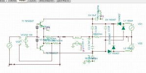
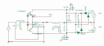
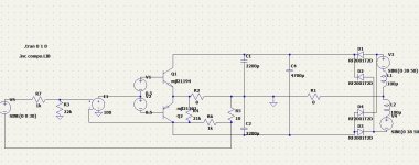
I did simulation with 21Hz square wave with 2.2mF on rails and 4.7mF C3 mutual. As there is a beat, I captured the min. and max.


I increased the output to let it starve showing the output voltage instead of current with floating and standard 4.7mF rails.


The resistance 10 ohms or 3 ohms doesn't change mutch.
I increased the output to let it starve showing the output voltage instead of current with floating and standard 4.7mF rails.
The resistance 10 ohms or 3 ohms doesn't change mutch.
H
HAYK
The real reason I am dealing with floating supply is lack of bass in split supply.
I realized first from single supply of bridged amp bass performance compared to split supplied single with LM3886 which is notorious to lack deep bass. By using a full floating supply which is called floating ground, the same circuit got the bass frequencies resuscitated. I thought then to have invented it, but not, Onkyo had produced high end amps using it with a pair of diodes linking the ground to the central point of the secondaries to limit the voltage of rail capacitors. Minek showed an old Russian design of late 80's using such supply. The problem with floating supply, each channel needs its own, whereas here as low frequencies are common for both channel the crosstalk is not a big problem.
About a year ago, I wanted to try the Chinese TDA2050-LM1875 chips, they have the same chip, to my surprise it is a new design with unity gain stable. I first tried it with two 24v SMPS, sounded full bass. When I made it with floating supply using single 48v, it didn't get any better. I tried the same circuit with the Shanxin TDA7294, with two SMPS, dried out bass. I bought dual +/-36 SMPS , in vain, the same result but better with floating.
What if the positive input, referenced to ground is the one that is making the amp positive feedback, so with the same dual supply , I let the positive input referenced to virtual ground made just by two resistors from the rails, by passed to eliminate only high frequencies. The bass came back as could with floating supply. If virtual ground can be used with SMPS, it cannot with linear type as the ripples that aren't always symmetrical, enter the input to be amplified. This is why the real reason of semi floating supply.
Last edited by a moderator:
H
HAYK
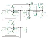
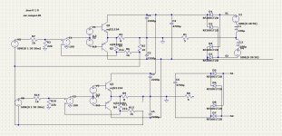
The question here is, does each channel needs its own bridge rectifier, and 3 capacitors ?
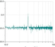
I simulated 2 channels one 30hz other 50hz with each rail capacitors, it looks on the spectrum, the crosstalk can be acceptable.

I simulated 2 channels one 30hz other 50hz with each rail capacitors, it looks on the spectrum, the crosstalk can be acceptable.
Attachments
H
HAYK
On steady state, the semi floating provides higher voltage than the standard. The loss due to resistor occurs in infra sonic to DC region that allows you to add a fuse and protect the loudspeaker in case of amplifier damage. This saves speaker protection circuit but in expense of double voltage rating of rail capacitors.What's the max output voltage with semi-floating PS vs standard PS? What's the power loss on R2 in case of semi-floating PS?
Hayk, a polyswitch instead of a fuse would be self resetting for short term DC or a high level of infrasound. And no intrusion on the signal path for normal use👍.
H
HAYK
I didn't knew about polyswitchs, thanks for the hint. I have looked upon ordinary PTC that measures several ohms cold and several kohms hot. These are real switches as it is only 0.04 ohms for 3A 60v. The volt is probably max. open circuit.
https://www.aliexpress.com/item/1005005334886883.html
The price is cheaper than high quality fuse holder. Main suppliers asking $0.8 a piece.
https://www.aliexpress.com/item/1005005334886883.html
The price is cheaper than high quality fuse holder. Main suppliers asking $0.8 a piece.
Attachments
Hayk,
Yes the 60V is maximum continuous tripped voltage. I was searching for an LTspice model for PolySwitches and found this
https://www.vishay.com/files/whatsnew/doc/ff_FastFacts_LT_SPICE_PTCEL_CL_TL2.pdf . Unfortunately it is encrypted and I didn't see any unencrypted LT models. I assume these encrypted models are specific to each PolySwitch and you can't change to parameters. Does anyone know if you customise their model?
In your semi-floating amp you may be OK with a RXEF025 that trips at 0.5A in 4 secs (faster if the current is higher). If your series resistor is 5 ohms then the maximum current with a fault will be about 30V into 11 ohms (6 ohm vc) or 3A and then should trip in under 1 second (similar to a fuse).
Can your speaker survive 3A for 1 second?
H
HAYK
The Amp is to be 65W. 3A with 6.8ohm DC resistance of the speaker is 61W.
If an output is shorted, the speaker +5ohm will see 36V, this gives a current of 3A.
If someone will be using in bi amplifier, as a woofer + low power full range, then the user must dimension the fuse.
If an output is shorted, the speaker +5ohm will see 36V, this gives a current of 3A.
If someone will be using in bi amplifier, as a woofer + low power full range, then the user must dimension the fuse.
H
HAYK
I think I understood why the Chinese TDA2050-LM1875 has full bass with split supply and not the TDA7294. It can be the very low Early of the driver+output transistors, whereas the later is DMOS with very high Early. This what the simulator showed.
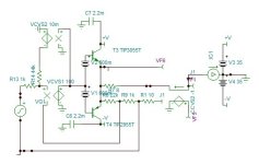
There is a means not practical but possible to decrease the positive feedback on the positive input, is to use the normal ground loop breaker but instead of grounding the dividing resistor (R14) to eliminate crosstalk, is link it to inverted output. Here I need to add two transistors on the positive branch of the LTP. It will be planB if the this PSU could not achieve.
There is a means not practical but possible to decrease the positive feedback on the positive input, is to use the normal ground loop breaker but instead of grounding the dividing resistor (R14) to eliminate crosstalk, is link it to inverted output. Here I need to add two transistors on the positive branch of the LTP. It will be planB if the this PSU could not achieve.
Attachments
H
HAYK
LTspice Help has "C. Capacitor Syntax: Cnnn n1 n2 <capacitance> [ic=<value>]" AND
One way to set the capacitor IC value is to do a normal .trans (without UIC) and wait until steady state is reached, then probe the capacitors final voltage and set capacitor ic=<myvalue>, then add the uic to the .trans, and it should run without (much of) a transient.
Also, there is a way to save the final voltages after a run to a file and reload them for another run but I have never needed to use it yet.
"used only if uic is flagged on the .tran card" |
One way to set the capacitor IC value is to do a normal .trans (without UIC) and wait until steady state is reached, then probe the capacitors final voltage and set capacitor ic=<myvalue>, then add the uic to the .trans, and it should run without (much of) a transient.
Also, there is a way to save the final voltages after a run to a file and reload them for another run but I have never needed to use it yet.
H
HAYK
- Home
- Amplifiers
- Power Supplies
- Semi floating split supply vs standard PSU