DC filament supply - SMPS or linear ?

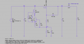
I am designing two tube units with a filament current requirement of about 3.5A at 6.3V and I am debating which power supply topology to use.

Initially thought a simple linear supply with a 1084 regulator would do the job, the problem is a power transformer with about 6A winding, which would be too big for the 2U rack chassis I am using. The power transformer also needs winding 250V @ 130mA for the HT and 12V @ 1A for relays and LEDs.

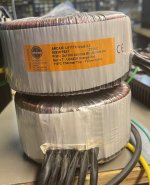
A possible solution to overcome the size limitation would be using an EI transformer for ht and aux supplies and a separate toroidal transformer for the filaments,
However, even with the relatively lower hum radiation from the toroid I am still a bit concerned about noise since the input circuit works at microphone level.

I have started considering SMPS for powering the filaments, this is the first time I use them with tube circuits.
First of all I don't know if having the SMPS inside the same chassis with the audio circuits can create noise problems? This would be my main concern.
I guess there shouldn't be a problem with mains frequency hum but what about the switching noise, can it be picked up by the sensitive high impedance circuits and if that's the case could the issue be solved with some steel shielding rather than expensive mu metal ?

Another issue, I need to stick to 6.3V tubes and the choice of SMPS module is a lot more limited than 12V.
I am wondering if a 7.5V module with a resistor on the output would be the best thing to do despite the extra heat generated.
I have read some of the adjustable SMPS can be modified by altering the resistances in the adjustment section, but I am not sure if all modules allow that and if there are potential side effects to consider.

Something like Meanwell RSP-75-7.5 mounted inside the chassis and an EI transformer for the ht and 12V fitted on the back panel should get the job done and cost less than a large all-in-one power transformer, and also compared to the solution with separate 6.3V toroid.
From what I understand SMPS don't need additional filtering for filament supplies so I would also save money on rectifiers, filter capacitors and regulators.

Of course I would be interested in any alternative solutions you might want to suggest.
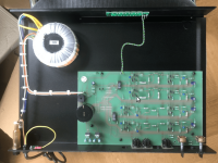
RCA wiring options

Hi everyone. So I am looking at a multiple amplifier system, 2 main amps with 2 subwoofer amps, designed for an entire house. There is quite a mess wen it comes to the RCA connections in the back, with some having to be splited to feed the signal to multiple devices. I am looking for a simpler option, maybe thinner RCA cables than standard. Any ideas or suggestions are greatly appreciated. I noticed the RCA patch panel option and that could work because all these amps are rack mounted, but just wanted to see if anyone has another suggestion, including what cables are best used in this case and if using a patch panel is the best possible option?

Thank you.

  • Poll Poll
Quiet amplification choice for BMS 18N862 8 and 4 ohms. Crown XTi vs XLi vs XLS or else?

Which amp config would you prefer for driving 2x BMS 18N862 8ohm and 2x 4ohm (each in its own box)

  • 1. XTi 4002 2x 1200W for 4ohm and XLi 3500 2x 1000 for 8ohm

    Votes: 0 0.0%
  • 2. XTi 4002 2x 1200W for 4ohm and XLi 3500 1x 2700W and XLi 2500 1x 1500 for 8ohm

    Votes: 0 0.0%
  • 3. XTi 4002 2x 1200W for 4ohm and XLi 3500 1x 2700W and DSi 2000 1x 1600W for 8ohm

    Votes: 0 0.0%
  • 4. XTi 4002 2x 1200W for 4ohm and XLi 3500 1x 2700W and Xli 2500 1x 1500W for 8ohm

    Votes: 1 100.0%
  • 5. XTi 4002 2x 1200W for 4ohm and DSi 2000 1x 1600W and Xli 2500 1x 1500W for 8ohm

    Votes: 0 0.0%

Hi All,

I wonder which would be better or simply your choice of amp to drive following drivers (each in it's dedicated sealed box) 2x BMS 18N862 8ohm and 2x BMS 18N862 4ohm?

I am choosing between following amps and I can mix and match:

1. Crown DSi 2000 - 1600W bridged in 8ohm
2. Crown XTi 4002 - 2x 1200W into 4ohm
3. Crown XLi 3500 - 2x 1000W into 8ohm or 3700W bridged into 8ohm
4. Crown XLi 2500 - 1500W bridged into 8ohm

It is almost pure AB for XLi (SMPS + Toroidal) vs less pure AB with SMSPs and AD - DA conversion that cannot be defeated and which I don't need due to MiniDSP in the chain.

I could use XTi 4002 to drive 2 channel 4ohm load at 1200W each and XLi 3500 to driver the 2nd pair of 8ohm drivers at 1000W per channel. Or 4002 for 2x 4ohm and bridged XLI 3500 for one 8ohm (3700W into 1500RMS driver with peak power handling of 3000W - how safe would it be?) and DSi 2000 bridged at 1600W to do 2nd 8ohm driver?

I don't need DSP (as I have MiniDSP Flec balanced) but I don't mind having it.

It is purely on performance front as there are some differences between them I thought.

I have the mix of 2 4ohm and 2 8ohm drivers as I was able to source the 4ohm pair 2nd hand so I went for it (my choice would be 4x 8ohm).

How important it is that XTi can handle 2ohm load while XLi cannot for me if my 8ohm BMS drivers in theory don't dip at all below 8ohm (that question is in case I would decide to bridge Xli 2500 or 3500 in which case they drive only 8ohm loads).

bms_18n862-8_impedance_2011-12.jpg


Thanks

Technics RS 1700 R2R

Hi everyone

Can you advise me if it is correct?

photo number 1 .. dark blue capacitor like yours in the device. It is common and a suitable replacement is .. UPW Low Impedance ?

photo number 2 .. pale blue and purple... there are far fewer of them on the board, even in the device a suitable replacement is .. UKL Low Leakage ?

photo number 3.. small black capacitor a suitable replacement is Fine Audio or ?

Dark blue ones have an additional letter designation ODC
Pale blue violets have no additional letter designation
Small black capacitors have an additional letter designation ODA

because 40 years ago, the manufacturer installed different colors and sizes of capacitors, but both the first and second types are on one board and they have the same values.
Even the small black one has the same capacity value, but it has much smaller dimensions.
The value 10uF/16V is the same for all, but the color marking and the size also differ.

Can you give me advice please and this information will certainly help other beginners as well.

Best Regards

Attachments

  • Cap 1.jpg
    Cap 1.jpg
    326 KB · Views: 109
  • Cap 2.jpg
    Cap 2.jpg
    406.8 KB · Views: 93
  • Cap 3.jpg
    Cap 3.jpg
    270.8 KB · Views: 99
  • dark blue A.jpg
    dark blue A.jpg
    303.5 KB · Views: 104
  • dark blue B.jpg
    dark blue B.jpg
    317.1 KB · Views: 100
  • pale blue violet A.jpg
    pale blue violet A.jpg
    235.7 KB · Views: 96
  • little black ones A.jpg
    little black ones A.jpg
    339.7 KB · Views: 103
  • little black ones B.jpg
    little black ones B.jpg
    302.5 KB · Views: 105
  • little black ones C.jpg
    little black ones C.jpg
    304.7 KB · Views: 98

Searching for Part Number/Manufacturer/Supplier info for Plug Connectors used in Eden Bass Amps

Hi,

Does anyone here know where I can source the plug connectors shown in the attached pics of my Eden WT-1205 bass amp?

Thanks.

Attachments

  • IMG_1235.jpeg
    IMG_1235.jpeg
    432 KB · Views: 67
  • IMG_1237.jpeg
    IMG_1237.jpeg
    336 KB · Views: 68
  • IMG_1238.jpeg
    IMG_1238.jpeg
    305.4 KB · Views: 71
  • IMG_1239.jpeg
    IMG_1239.jpeg
    453.2 KB · Views: 62
  • IMG_1240.jpeg
    IMG_1240.jpeg
    350.2 KB · Views: 72

Could use some help repairing my HP 339A

Hi all,
My HP339A distortion analyzer has a defect:
-the meter-dial allways goes full tilt, no matter what setting or function I select (osc. level. , dist level, or input level).
-On a scope, the monitor-output when set to osc. level shows a 50Hz, 5mVpeak jagged wave.
-the monitor-output, when set to osc. level, show a wideband noisely line of about 1.5mVp

Some years ago, I connected the output of the HP339A oscillator by accidence to the High Tension supply of a tube amp. The oscillator was fixed easily as only the safety zeners were shot. Maybe more then just the oscillator output zeners were effected? or something entirely unrelated is going on?

Any help or suggestions are highly appreciated.

Regards and best wishes,
Thijs Schrama

Secap 9924 switch mode supplies

Hello .
Have theese two secap psu, 24v 1000w . I have removed the small voltage trimmer potentiometer, and added a 20 turn potentiometer.
Build quality is excellent.
Voltage regulation is circa 20 to 27 volt, ripple is really low under load.
150 euro for the pair.

Attachments

  • 20200702_154504.jpg
    20200702_154504.jpg
    460.3 KB · Views: 87
  • 20200629_121252.jpg
    20200629_121252.jpg
    380.8 KB · Views: 91
  • 20200629_121207.jpg
    20200629_121207.jpg
    376.2 KB · Views: 86
  • 9900-new-eng.pdf
    9900-new-eng.pdf
    1.1 MB · Views: 64

For Sale Arcam P7 parts

Prompted by another ad I suddenly remembered that I have 4 unused Arcam P7 power modules. One module had given up its input socket, otherwise they are pristine.

I also have the original boards that go with them. See pictures.

The two original mains transformers are also at hand.

Realizing that the weight will be high, maybe it will mostly attract buyers from Scandinavia, but I’m willing to ship anywhere.

I would like to get $500, excluding shipping.

Regards
R

Attachments

  • IMG_9166.jpeg
    IMG_9166.jpeg
    329.8 KB · Views: 203
  • IMG_9165.jpeg
    IMG_9165.jpeg
    472.1 KB · Views: 172
  • IMG_9164.jpeg
    IMG_9164.jpeg
    420.1 KB · Views: 176

WTB cheap 2 way 12db/oct active 2 way xover

I already have a good 24db.oct 2 way xover but I need a 12DB/oct
active xover with a 200hz low pass and 500 high pass. I already
have the Pass crossover kit from the DIY store but am to damn lazy
to build it right now . So I just want something dirt cheap to use for
a while. Or if one of you just want to build this Pass crossover for me
let me know.

Audio serial port

Not sure that is the correct title but there are devices that use 3 line audio serial port (names can vary), but using CS8412 as example:
SDATA - Serial Data - audio data serial output pin
FSYNC - Frame Sync, - delineates the serial data and may indicate the particular channel, left (high) or right (low)
SCK - Serial Clock -serial clock for SDATA pin

SM5813AP oversampling filter) uses these 3 signals as input and demultiplexes them to separate left and right serial data outputs (DOL and DOR) which can be fed to two separate DACs e.g. AD1862. The demultiplexing to 2 channels is somewhat unusual as most audio devices and DACs do not use that. Also this device has DG - deglitch control clock - that can clock data to the DACs on negative going edge.

Can two separate single channel DACs be driven from the audio serial port? The FSYNC is used to clock the data in and mask off the appropriate channel on the SDATA line (some logic gates are involved) so the signals look like the illustration as below, the SDATA shows left/right channels on the same line.

So the "obvious" problem is that one of the channels is received at the DACs before the other - is that going to be a problem?
The minimum frequency of FSYNC is 44.1 kHz x 2 (sample rate of CD, both channels are sampled at 44.1 kHz) but it can be higher if oversampling is used.

The speed of sound in air is 340 ms-1 so in 1/44.1 k seconds, the sound will have travelled just under 8mm in the worst case scenario, so it will "sound like" the left channel is 8 mm nearer - surely that won't be noticeable or am I missing something?


1700733705807.png

OPA2134 op-amp obsolete?

Just received a message from Digikey that the OPA2134 in various forms is being obsoleted.

I'm not sure if there will be a new version in the near future, but Digikey is completely out of stock of all forms of the OPA2314 op-amp.
This has long been one of my favourite go-to op-amps.
I think it sounds pretty damn good, and I've used it to improve the sound of various components, most of which came with NE5532 op-amps which are pretty generic jelly beans at this point.

Anyway, I was wondering what good sounding substitutes for the OPA2134 are out there.
What are you guys using these days that doesn't cost ten bucks?

Amplifier to be built in a fully enclosed speaker box: how about heat?

I want to transforming two vintage passive speakers, into active speakers.
To do so I intend to use:
  1. Two Mono amplifiers (one for each speaker) producing 50 watts.
  2. An AC/DC PSU to drive amplifiers.

My question
Both the Amp and the PSU will produce heat. And the inside of the speaker casing is completely filled with damping material. The PSU has a case to keep the damping material away from components. And I will make a case to protect the Amp too. But will this get too hot or not, since the speaker enclosure is air tight?
  1. Does anyone have experience with building these two components in a fully/air closed speaker box?
  2. Can this be done, or do I need other precautions?

Cambridge Audio A500 completely replace Pic Micro / Remote control with custom codes.

Hello, this is my first post.
My son's Cambridge Audio A500 amp volume remote control stopped working with his new setup and he has no remote control that works with it.
As he's lazy and minted (LOL) he decided to buy a new fancy Sony AV amp and gave me the A500 amp to hack about with. The motorised pot was broken (I swapped in an ALPS I already had) and the BA6218 motor driver also needed replaced after an unfortunate mix up with connectors (fzzzt).

I noticed almost immediately on inspection of the schematics, that the PIC16C54 is the same pinout as a 16F628a that I have lots of and is cheap, and had already written IR code in PROTON basic for a more complex preamp I made over a decade ago that also had extra features including input selection...
I modded the code in a few minutes and it now reproduces the ON LED and Vol UP/DOWN IR of the original A500, but "pretends" to be a Sony TA-E77ESD preamp.

This means the CA A500 is compatible with far more (cheap) universal remotes.
With a bit of tweaking and IR code look ups, it could be made to respond as almost anything required.

As a bonus, CrownHill Proton Basic is now end of life and free:

https://www.crownhill.co.uk/category-41.html

Files attached are the Proton basic file and a hex for programming the Pic.
I wonder if anyone else in the universe might find this useful? (haha)

Cheers.

Attachments

2SK60 2SJ18 Sony VFETs

First of all, please read my post here, and see the pictures:
https://www.diyaudio.com/forums/pass-labs/370689-diy-sony-vfet-builders-thread-202.html

I am listing what I have below. I bought these from a sony repairman who assured me the VFETs are all good. I will carefully test each one and post the results here, ASAP. Give me a few days to test them with utmost care.

I would like to sell them for 135 USD each pair, given the scarcity, the demand and given that I much need the money at this time.

This is a preliminary list, subject to change according to test results and buyer interest:

1 complementary set, rank 55, price 270 USD (reserved to volpar)

1 complementary set, rank 55, price 270 USD (volpar?)

2 pairs of 2SK60, rank 55, price 270 USD (triode_al?)

1 pair of 2SK60, rank 56, price 135 USD

1 pair of 2SK60, rank 45, price 135 USD

1 pair of 2SJ18, rank 52, price 135 USD

1 pair of 2SK60, one is rank 57, the other is either 53 or 58 (faded lettering), this is T.B.D. by test.

I also have to figure out shipping and insurance cost, and set up paypal because I haven't used it in years. Payment after I have test results AND everything figured out. I will keep you posted here.

Thanks,
Alex

Attachments

  • 1.jpg
    1.jpg
    132.9 KB · Views: 1,041
  • 2.jpg
    2.jpg
    56.7 KB · Views: 986

AC volt meter instead of Vu meter.

I like the look of old analogue VU meters however they don't actually display much of use.
A bit of mental maths and I could convert the VU to something usefull but I would rather see a display of the AC voltage of the signal at the output.

I've been pondering if I could connect an analogue AC volt meter across the outputs of an amplifier.

Something like:
https://www.aliexpress.com/item/100..._id=202311240101066275243863642730003680140_2

Is there any reason this wouldn't work?

Would it have a negative impact on the sound of the amplifier?

Simple High Voltage Regulator

The idea started from His Masters Noise phone stage. This make use of a simple and efficient CCS, that is based on two depletion mosfets arranged into a cascode a la Erno Borbely. This work very well !
Later on, I have started to work on Zeno MKII and I ended up with a simple regulator that make use of LT3042. At the hart of LT3042 operation is again a very low noise CCS that feed a resistor. Is a simple and elegant solution to get a low noise reference voltage. Maybe some similar jfet cascoded solution is inside LT304X series.
Using the idea from LT3042, with the help of cascoded CCS, a simple, yet reasonable low noise, high voltage, regulator, can be achieved.
Operation is simple. Push constant current into a resistor and you have a voltage reference. Then use a high voltage mosfet to feed some usable current at output.
This is initial idea and it can be extended adding a current limiter for protection. For the time been I'll use a fast fuse.
I plan to pair the regulator with Saligny HVHF and a PCB will follow in KiCAD 5.99 as open-source project.

If you think that R4 is to high and may induce noise, CCS current may be increased from 1mA to 10mA - trough R3, at the cost of power dissipated on R4 resistor and M1. One one hand you reduce resistor noise, but on other hand you increase thermal noise and power dissipated in other parts. For me the "balance" is at 1mA and I'll keep that way.

Choosing a high voltage M1 & M3, this regulator may be also used to regulate very high voltages, maybe over 1kV.
Before going further, here is schematic and Ltspice file. Have a look and let me know your comments/critics.

Regards,
Tibi

KiCad ver.6 source and gerbers at post #20

Latest schematic -> Simple High Voltage Regulator
967404d1626414460-simple-voltage-regulator-hvr1-jpg

Attachments

  • Hvreg.png
    Hvreg.png
    91.2 KB · Views: 1,796
  • HVreg.asc.zip
    HVreg.asc.zip
    1.5 KB · Views: 235

Sylvania Console Budget Rebuild Advice - 2-Way or 3-Way

This is a 1971 Sylvania Console I got for $50.
  • 10" "Air Suspension" Woofer
  • 3" Mid
  • 2" Tweeter
  • Original Amp 2 x 50w
The original record prayer looks pretty cheap. I have a Yamaha P-05 turntable I am planning on using. I might repair the original amp, but not anytime soon. I am planning on using an affordable Chinese pre-amp and amp.

The Multi-Way design question:
  • Enclosure for the 10" is around 1.2 sq ft
  • The 3" mid does not have an enclosure and sits in a 2" deep space between the OSB for the 10" woofer. (2nd pic)
I'm not looking for anything great sounding just decent for getting into vinyl and some wifi audio playback.
I'm thinking about forgetting the tweeter and going with a 2-way with a full-range 3" to keep the crossover design simple. I imagine I'll have to change the crossover a couple of times to get it to sound decent.

For the 10" Woofer I am thinking of a Dayton Classic DC250-8 and filling the enclosure with poly-fill
For the 3" Mid / Full-Range I am thinking about FaitalPro or Peerless. They both fit in the 2" deep gap (2nd pic), and stuffing the surrounding area with poly-fill to see if it sounds acceptable.

IMG_8554 Large.jpeg

IMG_8557 Large.jpeg

IMG_8556 Large.jpeg

IMG_8555 Large.jpeg

IMG_8558 Large.jpeg
  • Like
Reactions: Duke58 and GM

Testing White Noise Generator Devices

White noise from speaker or headphones can promote relaxation. White noise is flat for the audio spectrum, the mind soon knows the random sound contains nothing of interest to process so it can relax. White noise occurs naturally in oceans and waterfalls however that source is interrupted by the spurious sounds of breezes and birds. There is additional loss due to the quality of recording gear.

There are several methods for electronic generation of white noise. I tested two: (1) analogue white noise by exploiting the breakdown characteristic of a transistor emitter-base p-n junction. (2) digital shift registers. (more deterministic and reliable)

1. 2N3904 Transistor

The ONSEMI document has a single entry "Emitter −Base Breakdown Voltage (IE = 10 microAamp-dc, IC = 0) .. 6volts"
and nothing is explained. This is typical for transistor data. Since transistors are intended for amplification or forward switching, the breakdown characteristic is a bug, not a feature. However, this bug can be exploited to produce white noise by avalanche provided that the circuit topology limits the 10 microamp flow.

There is an abundance of white noise circuit variations on the WWW. I copied one that has two transistors gained by filtered negative feedback which I could observe on my economy oscilloscope. However, here is a careful design with quality documentation...
Random Sequence Generator based on Avalanche Noise (Giorgio Vazzana) .. It is much better than mine which comes without documentation...

diy-1.png


Note: TBD items are optional. Q2 must have a 10X scope probe -- a 1X probe can cause clipping.

clip1.png

clip3.png


2. Digital Shift Registers

The Linear Feedback Shift Register (LFSR) algorithm can produce a pseudo-random stream of bits. It is interesting to design hardware shift registers for random noise LFSR, they are well defined. However, it is more practical to use the registers of an MCU such as Microchip PIC. I got a couple with the PIC12F65 LFSR-1B firmware from https://electricdruid.net/

druid-intro.png


pic_sch1.png

Download the document which shows the PIC with Pink Noise filter for audio testing.

bshot1.png

bshot2.png


[1] https://www.edn.com/white-noise-source-flat-from-1hz-to-100khz/ (using a Zener 1N759)
[2] https://sound-au.com/project11.htm (pink noise for audio testing)
[3] https://www.analog.com/en/design-notes/whitenoise-generator-has-no-1f-component.html

A Battle With Hoffman!!!

I'm working on a DIY set of small(ish) speakers. Will probably put them on stands. I got a good deal on a pair of KEF SP1632. What would be a good low end to pair with them?

***originally I was going to try and use daytons audio's 5 1/2" epique woofer. The KEF has a sensitivity of 93db while the epique only has 83db. I was looking at maybe investing in a pair of subs from one of paradigm's high end speaker

Supertweeter Amplification and Protection

Yesterday I found that one channel of my supertweeters had died. Each channel has a forward firing unit and a backward firing unit. The forward firing unit is a Dynaudio D21AF, which has on-axis response to 40kHz. The backward firing unit is a Vifa NE19VTS-04, which also has on-axis response to 40kHz. Both drivers in the left channel had died and measure open. The drivers in the right channel seem to be ok.

I'm a follower of the idea that supertweeters make a difference, and in sighted testing experiments they always have. I have not felt that the effect was large enough to pass a blind test so I haven't bothered. I still believe the effect is real and wish to continue using supertweeters. But only after the recent failure did I decide to move my supertweeter assemblies (a tower made from a speaker stand and old speaker) out from in between my two main speakers (Acoustat 2+2 C-modded) to check that out, and I discovered that moving all that stuff out from in between the speakers was a bigger positive effect than I ever (imagined?) the powered supertweeters to be providing. So my next generation supertweeter system will be mounted more discretely behind and possibly also in front of the main speakers rather than to the side, where they interfere with the normal dipole and front wall reflections. So I'm not going to resume supertweeting until I have a whole new physical arrangement. Plus I need to obtain replacemet drivers. Both kinds are currently unobtainable new but I've ordered both on an auction site. One seller first time around cancelled the order due to unavailability so I'm not counting on anything until I have the replacement drivers in hand.

But I'm wondering if I should re-think the power amplifier part of the setup as well. I've been using an ATI 1502, rated at 150W/channel (probably has at least 200W before clipping). This seems like it might be excessive power, though both drivers seem to have ratings which suggest it is OK. I'd long planned to build a 25W/channel class A amplifier instead. But I'm not even exactly sure 25W would be sufficient. Most of the time the output is very tiny fraction of a watt, but perhaps for some brief instants it isn't. And if a 25W "class A" amp actually has more like 50W peak power, it could still burn the tweeters in a similar way. So then what about 15W, etc.?

Whatever happened did not destroy the amplifier, which is still being used because it's a 33 year old survivor. I could continue to use the same 150W amplifier and add a speaker fuse. I'm thinking a 1 amp fuse or less in slo blow. If I were sure that only tiny power were needed, I could add an attenuator, say with 1 ohm on the bottom and 11 ohms above for a fraction of 1/12. This would only add 1 ohm series impedance, which is probably fine. I have always used both digital electronic and physical crossover on the tweeters. The digital part is a 17kHz high order high pass linear phase FIR filter generated using RePhase and running in a miniDSP OpenDRC. The physical part is 0.47 uF capacitors in series with with each tweeter, which serves to protect it as well as eliminate hum from the amplifier. At 20kHz this capacitor has about 17 ohms impedance anyway. (That also increases the power required from the amplifier. If I made a 25W amplifier, it would have to be very hum free so I could avoid using this "protection" capacitor or use a larger one.)

In fact I wonder how the drivers got destroyed. Since I can't directly hear the supertweeters, I have no idea how long the right channel had actually been dead. I only decided to test the tweeters when one other thing in the series of components used--a Behringer DEQ 2496 which I used to monitor the supertweeter signal and fine tune the level in the digital domain, had died and was not passing signal. But after removing that, I found the supertweeters were still dead in one channel and I traced the problem to open windings in both drivers.

(Note: after the SPDIF digital signal passes through the DEQ for final monitoring and adjustment, it goes to an Emotive Stealth DC-1 dac for conversion to analog to produce the unbalanced analog signal that drives the ATI 1502 amplifier. So even when the DEQ died, it could not have directly produced a dangerous voltage at the input of the amplifier. The DC-1 was generally set to +7dB amplification and was turned even higher during testing, but it would have to receive an intact digital signal to be producing any output at all.)

I had been successfully using this arrangement without issues for over 4 years, including a large number of power failures and restarts, etc. Nothing damaged the tweeters until recently. They were measured and working fine a month ago or so.

My guess is that at some point an input cable came disconnected and produced a full power 60Hz from the amplifier. If this were hard clipping the amplifier, it could look like a 60 Hz square wave. That might deliver enough power to burn out the tweeters even through the 0.47uF series capacitor. That kind of issue could be a problem regardless of using a low power amplifier, and to protect against it either a fuse or an attenuator might be good (but might also be ineffective).

Although I was mostly very careful, this could even have happened while I was in the process of testing the tweeters after the digital equipment failed.

So the question is, should I use fusing, attenuation, or some other kind of protection on the tweeters next time around? Should I be using a lower power amplifier (what kind and how much power) instead of or in addition to protecting with a fuse or whatever?
  • Like
Reactions: karellen

Onkyo P3060R recap

Hi users
what are the most suitable replacements please?
Onkyo P3060R
Green Cap Nichicon LN(M)
100uF/50V 2x
47uF/50 4x
22uF/50V 4x
.... Low Impedance or ??
Dark Blue Cap Nichicon SE(M)
10 000uF/50V 2x
1000uF/25V
470uF/16V
330uF/16V
100uF/25V
100uF/50V 2x
100uF/10V 2x
1uF/50V 8x
47uF/16V
22uF/16V
...Low Leakage or ESR or Audio Grade or ??
what are the most suitable replacements please?
Thanks in advance for help.

Attachments

  • Met Mylar Onkyo.jpg
    Met Mylar Onkyo.jpg
    343.3 KB · Views: 70
  • Nichicon LN M.jpg
    Nichicon LN M.jpg
    309.1 KB · Views: 70
  • Nichicon SE M.jpg
    Nichicon SE M.jpg
    289.7 KB · Views: 79

Testing the SSM-2044 IC

I’m working on a Korg PolySix synth that has at least one dead SSM-2044.

Going through the Adjustment Procedure from the service manual, I got to step 4 (2) 2) where I’m supposed to confirm a sawtooth wave coming out of each voices. However, of my 5 remaining working SSM-2044, 3 give me a sort of double peak sawtooth, and 2 only give me the top half of a sawtooth (sharks!). Pin 5 looks especially different on the group of 2 vs the group of 3.

The differences follow the chips when I swap them around from voice to voice, so I’m pretty sure that the SSM-2044 are the root cause.

All 5 of these chips still produce sound, but the group of 2 sounds noticeably different from the group of 3, so it’s not a good setup for a synth.

I’m assuming that the group of 2, which don’t produce as much of a sawtooth wave, are the “more defective” ones, and that the group of 3 are probably good. But that's an assumption, and it would suck to order some replacements only to get different sounding ones. I'd also want to make sure the group of 2 is actually defective and not just different. I wouldn’t resell defective ones, but if they are just different I will. If they have failed, they have failed in identical fashion, the half sawtooth is the same on both.

The batch numbers don’t all match on all my chips, but that doesn’t seem to be a factor in how they sound.

Is there a way to test these chips for defects, or partial failures? (voltage drop specs across pins? test jigs?)
A good way to tell if they are actually defective, and to tell fully functional ones?
Is my assumption correct that the 2 half-sawtooth ones are defective (the PolySix is, in itself, a test jig after all)?

Thanks for any insights!

Choice of Treble Drivers in a High-Efficiency 3-Way System

My high efficiency system that I am perfecting is based on an Altec 414 Z in about 50 litres volume , freq. range 50 hz - 700 hz + JBL 2420 in biradial fibre Horn RCF - 700 hz - 6000 hz , as tweeter Ev. T35 , but the latter was only lent to me by a friend , to replace it validly , given the unavailability of the T350 model at decent prices for its age .
A good friend who is very knowledgeable on the subject , seeing that my drivers are in alnico and therefore the sound is in any case quite different from other materials , has advised me using a tactrix wooden horn of about 135 mm. in output width and 60 mm. deep , obviously with throat . or the Radian 475 PB with an aluminium diaphragm or the BMS 4540 with a synthetic ring diaphragm and a one-inch throat, what I am a bit afraid of is the sound signature in a vintage box, bearing in mind that the amplification is quite vintage and the crossover would be set up by me using Clio, which I know how to use quite well.
Regards
Roberto

Clarification on Morgan Jones choke input snubber

I've been reading up on tube-rectified power supplies and currently working my way through Morgan Jones' excellent book. That said, I'm a little unclear as to the section regarding snubbers on choke input power supplies to help with smoothing. My confusion is purely based on my reading of the diagram and my desire to understand choke input power supplies. The image below depicts a typical snubber approach on the left and an improved snubber on the right.

The way I'm reading it is that that in the improved snubber on the right, the 265 Ohm resistor represents the internal resistance of the choke and NOT an additional resistor. Is that accurate?

A bigger picture question is why don't I see these snubbers in more schematics with choke input power supplies?

Thanks in advance!

Screen Shot 2023-11-22 at 12.28.35 PM.png

Transistor LC filter based graphic eq

Hi guys,
I have been asked by one of my costumers if I could design a 12 band graphic eq with discrete transistors and LC filters.
I believe that discrete transistors aren't the best solution in this case but he was pretty sure that he wants to use them.
I came up with a basic formof the circuit but I would like some feedback from you if some of you have any experience with something similar of if you think that it is good Idea.
Thank you very much.

Attachments

  • Graphic EQ .png
    Graphic EQ .png
    14.6 KB · Views: 106

Confusing Voltage Section!

Hi there, This voltage section makes me puzzled! so far I guess that the problem in the voltage section. Please provide a solution to this issue. I already posted about that and got some advice. according those suggestion I have made some changes. My understanding of electronics and amplifiers is quite limited. Would you guys kindly assist me?
diagrams, both the original and updated versions, are attached.

Attachments

  • main_diagram.png
    main_diagram.png
    51.8 KB · Views: 155
  • update_01.png
    update_01.png
    99 KB · Views: 150

Please help me to solve the Unbalanced Bias voltage and The DC Offset

Hi there, Please provide a solution to the issue. I know very little about amplifiers. I purchased an amplifier board a few days ago and tried to sketch the circuit diagram. Both the original and the suggested diagrams are attached.
Regards -- opu

Attachments

  • amp.jpg
    amp.jpg
    132.3 KB · Views: 175
  • ampx.jpg
    ampx.jpg
    139.8 KB · Views: 175

NAIM use Tantalums for coupling caps in their IXO Active Crossover - good or bad?

I recently won an IXO crossover and decided to check on what I thought was a loose Din socket.
On opening it, I noticed that :-

  • The 18db/oct filters used Zetex (formerly Ferranti) ZTX transistors - not an IC in sight (a refreshing change not to see NE5523/34 opamps)
  • The LF & HF 50k level controls are wired unusually - wiper to the input sockets with a 4k7 series resistor to prevent a dead short of the preamp output on minimum. (20k on max)
  • The single rail power supply uses a LM317 set to 24v - one for each channel.
  • The input, output and interstage coupling capacitors are Tantalum. 10uf/35v

Now I don't remember ever seeing Tants used for this purpose. Usually a standard polarised electrolytic would be used on single rail designs.

I have to say the crossover has made a significant improvement to my 35yr old SBLs. (Quad 306 driving the bass/mids and derated Krell KSA50 clone for the Scanspeak tweeters.)
I found myself listening for 4hours yesterday evening, about twice as long as I usually listen so I am not planning any "upgrades" to the IXO.

Attachments

  • ixoinside.png
    ixoinside.png
    149.3 KB · Views: 392

Full Range Driver vs Coaxial Questions

Hello all,

A few questions if anyone has a moment to drop a little wisdom.

I'm a bit enamored with full range drivers and the simplicity of not using passive crossovers. What I'm thinking about may not be really feasible or the wrong tool for the job, but what's the harm in asking or thinking about it right?

I'm not sure if the following would be best suited to a particular full range driver (both single or two of them together in a bipole) or a coaxial with crossover already built in (I'm not sure which driver this would be, forgive me for not wanting to do a passive crossover for this, but I would entertain a coaxial with a crossover already in there if that exists).

I was thinking of a few build ideas with full range drivers. Application is all audio in my listening room which is fully duty for music, games and movies/shows. I rotate speakers and builds through this room fairly often and just like to try things. Looking to try some fun builds that sound decent. Seating is limited, so I don't need massive dispersion or coverage. Distances for listening are no greater than 4 meters (12~13 feet) but often a little closer than that such as 2 meters (6~7 feet). Goal is to be able to produce SPL in their working range into the 80's db range at those distances, if I can.

Build Question 1:

Full range bi-pole, similar to the microplanet mini castles. I was thinking of making them shorter, squatier, fatter bookshelves rather than towers with the drivers facing forward and up in a bi-pole arrangement. I'm not worried about getting deep bass, I would be totally happy with them being 60hz capable just so there's plenty of room to crossover with co-located subs paired with them, each. Figured this design has better off-axis response and with two drivers a bit better SPL output with power handling and xmax limits on so many drivers. Can't decide on a driver, I have seen many in several threads suggested from MA and Fostex. Would this be a wrong tool for the job to watch movies and shows considering they would be with subs and considering an SPL range of the 80's db at 6~12 feet?

Was thinking up to $200 in drivers per speaker enclosure. I would be looking to make 3 identical enclosures.

Build Question 2:

Continuing on the show/movie theme, I'm thinking of building some simple full range driver based atmos or height speakers. I can't decide if a coaxial with premade crossover or a full range driver would be better. This really only needs to get to around 80~100hz and then crossover. Was considering a larger 8" full range driver, or possibly exploring smaller 4~5" full range drivers in a bi-pole arrangement again? Or other? This one I was thinking potentially going sealed for lots of simplicity as these speakers would not be getting a lot of use frankly and truly do not need to produce much low end response.

Was thinking $80 in drivers per speaker enclosure. I would be looking to making up to 4 identical enclosures.

Thoughts on full range driver differences for the above applications that are small 4" vs larger 8" or more?
Thoughts on SPL differences of one larger 8" vs two smaller drivers?
Off-axis (greater than 30 degrees total, or say 15 degrees from center axis either direction) response differences?

Thanks so much for any thoughts.

Very best,

What can you learn from the physical characteristics of a driver?

If I was to SHOW you two drivers & you had to pick one - what would you choose? Both drivers are 8" and salvaged from ported cabinets with less than 20 litres.

In the RED corner: weighing in at 75w RMS is the JVC boasting just 3 ohms of resistance.

In the BLUE corner: The mighty Soundware XS driver. 100w of RMS power, more Xmax, champion 6 ohm driver.

You can have either for free

Which?

Klipsch Forte III bi-amp project / experiment

Hi folks. Happy Thanksgiving! (if that's something you celebrate). It has been many years since I posted here (I had to create a new account). It's good to be back and I look forward to seeing what people are creating these days.

In my holiday downtime I'm pondering a grand winter project/experiment. I have a pair of Klipsch Forte III, which I love. I currently drive them with a solid-state McIntosh MC2205 for both speaker inputs (not bi-amped). In the past I built a pair of 300B single-ended mono blocks and bi-amped with the 300B amps on the mid and high horns, and the solid-state McIntosh on the woofer/passive radiator. I miss the tube/horn combo. The Klipsch really love tubes. Thus, I'm interested in a new bi-amp setup perhaps without the McIntosh. I also want to compare single-ended and push-pull designs (I'm sure that will ruffle some feathers hehe).

At this point I am thinking about two differnt pairs of mono-blocks. One pair parallel single-ended and one pair push-pull. I want to use the same tube type for both amplifiers and I am thinking about basing them around KT88s or 6AS7s. I then want to try different bi-amp combinations of the two types of mono-blocks and the McIntosh and I really want to make as fair of a comparison as possible between the sound of the two very different designs (SE and PP) with the Klipsch. The Klipsch are super sensitive so making a ton of power isn't necessary. I imagine a 30-ish W push-pull design and well under 10W for the parallel SE.

Once designed I'll build the amps on MDF boards initially to conduct the experiment and then after finding what I like, will create final versions with nice chassis etc. And just for kicks, I acquired a full set of driver and output transistors and caps to rebuild the McIntosh. It's possible I'll keep both designs as they may shine for different types of content.

So to recap, I plan to design/build:

(2) parallel single-ended KT88 or 6AS7 based monobkocks
(2) push-pull KT88 or 6AS7 based monoblocks

I am open to suggestion regarding output tubes but want to stick with the same tube for both designs. The 6AS7 is attractive because of price, since I will need a bunch of output tubes (depending on how many end up in the parallel SE design). I think at a minimum 8 6AS7s (4 for each design). Also open to suggestion to existing designs, input stage tube types (I like 6SN7s and have used them in a few builds).

Thoughts?

Thanks for reading!

DIY Audio Switch for A/B double-blind tests

Hi Folks,

I needed a switch for upcoming A/B double-blind testing in the coming weeks (more about this in an upcoming topic - stay tuned!...).

While such simple switches are easily available online, I couldn't find any that could switch sources and outputs at the same time.

Being a big fan of reusing/modifying stuff as opposed to buying new, I had the idea to repurpose an old LPT Printer switch, which allows to switch between 4 printers connected to a single PC. I saved that unit from the scrap (actually, I took it out of the trash) in Montreal about 15 years ago, knowing I would need it one day. Well, the day has come!

Here are a few pictures of the modified box. I added a 4mm banana-connector on the front to connect the metal enclosure to earth if needed. Earth and signal ground are or course isolated from each other.

It turned out to be a 4-way A/B/C/D switch instead of only 2 positions...even better! Now I can tests 4 devices at the same time!

front.jpeg


For each of the 4 positions, the COM jack on the front is connected to one of the jacks on the back, and simultaneously the COM RCA is connected to the corresponding A/B/C/D RCA's as well. But the jacks and RCA's are completely independent. Therefore, I can use this box either as a jack switch only, as an RCA switch only, or both at the same time, which is perfect e.g. for testing different headphone amps by switching the signal between the source and the amp's input via the RCA's, and the outputs of the amp via the jacks (the headphone would be connected to the COM jack on the front).

back.jpeg

The switch itself is of very, very high quality (in fact, I use the same ones on DIY preamps). It has silver-plated contacts, nice solid feel, extremely durable...). the switch alone costs way more than 30 EUR if you want to buy it new.

inside.jpeg

I wanted to share this, I hope some of you will find it useful!

Cheers
Denis

Behringer EUROLIVE VP2520 problem

Hello! I have a problem with my two-way speakers. I have four of these speakers, and none of them work. It seems like i have overloaded them, with too much power, and that the protection circuit has turned on. The reason why i have come to this conclusion is that i have cross-testet amplifiers, cables etc.. All the drivers seem completely fine as well. I find it so odd, that all the speakers capitulated at the same time. The tweeter works on all of them but the two drivers will not work.

JBL TC25 tweeter

Hello.
During cleanup I found theese unused jbl tc25 tweeters, I also have the filters, which is a misely bipolar cap only.
Did some googling and it seemed to be a very nice tweeter.
Only spec I could find was
Frequency response (+/- 3dB) 3,500 Hz - 27,000 Hz
Nominal impedance 4 ohms
Sensitivity 91 dB SPL
Power Handling 50 Watts (continuous program) / 100 Watts (peak music)
And someone did mention that jbl 052ti could be similar.
Anyone here got some pdf or info on theese

Attachments

  • 20231123_084333.jpg
    20231123_084333.jpg
    259.5 KB · Views: 103

Optimal horn length for 15" and 18" TH ? (for PA use)

I'm hoping someone can give me a simple, ballpark answer. I'm considering an unusual subs project, making a TH design that is NOT folded into multiple internal channels. Rather, I'm considering building a long, thin box, with only one internal baffle. (My reasons to follow later, if the specs work out.)

I don't yet know how to use Horn response, etc, but just need the length. Let's say to get reasonably flat to 40 Hz, maybe with a touch of EQ but not too much.
Full dimensions would be even more helpful, if possible, but the total length (including the space the driver would be in) is my main need right now.

I need this for both an 18" (most likely the B&C 18SW115) and whatever neo 15" is currently considering best for TH subs.
I've seen some "unfolded" diagrams that look like around 9' for the 18" driver, but I need to be sure, and reasonably accurate.

-------------

Thanks a ton if you can get me this.

Simple SMPS with bidirectional synchronous rectifier for class D AMP

The power supply is quite primitive. The TL494 driver controls the FET power stage and synchronous rectifier via TGR. An LNK306 converter is added to power the driver on the high side.
Additional functions: soft start, current protection high voltage transistors, over-temperature protection, latch-off by external signal, STBY signal generation for the load.

Increased capacitance of capacitors on the high side, ZVS/ZCS mode in almost the entire power range.

The transformer is wound with ordinary wire, no gap in the core. Because of this, the transformer fabrication is very simple. Three industrial transformers of .3$ each are used to control the gates.

The main disadvantage of the product is a very high peak current at startup, if 10mF of additional capacitance is connected to the output, it will be difficult to adjust the protection.

TOP PCB.png
20230914_132747[1].jpg

Attachments

  • DRV.png
    DRV.png
    14.5 KB · Views: 230
  • G_DIS.png
    G_DIS.png
    4.2 KB · Views: 201
  • GEN.png
    GEN.png
    20.7 KB · Views: 194
  • HV_BUS.png
    HV_BUS.png
    7.2 KB · Views: 199
  • LNK.png
    LNK.png
    7.5 KB · Views: 210
  • POWER.png
    POWER.png
    77.5 KB · Views: 188
  • PROT.png
    PROT.png
    67 KB · Views: 191
  • TGR.png
    TGR.png
    70.3 KB · Views: 200
  • SDS00040.png
    SDS00040.png
    15.5 KB · Views: 188

Hello from Germany

Hello again,
I became a member in 2015 - I know it's been a long time. A lot has happened in the meantime.
In terms of health and world politics. Everyone knows what I mean. So I don't want to go into it any further.

I'm currently building a few power supply units for my motors. I'm looking for the Talema 70065K transformers.
I need at least 2 of them, but I'm happy to take a few more, like 5 or 7 pieces... contact me by mail: Info@AVDesignHaus.de


That's all for today.
Best regards Rainer

Any idea what this is, it seems to measure 12uF

Hello everyone,

I am rebuilding/refurbishing an old after market Linn LP12 power supply, and I have a noise that creeps in to the power supply (mechanical hum and ZZZ) when it's warmed up, it's as quiet as a mouse when cold. I am swapping out all the old caps as it's 35 years old, and I have not used it for about 20 years. I am also working on cooling the transformers.

But I have no idea what this is, any opinon?> the image is blown up, it's tiny, the red cap.

Scale shown and the red cap I am trying to identify is in the middle of the two 0.68uF white rectangular caps/

Thanks!

Attachments

  • Screenshot 2023-11-17 at 17.15.23.png
    Screenshot 2023-11-17 at 17.15.23.png
    548.2 KB · Views: 227
  • Screenshot 2023-11-17 at 17.17.01.png
    Screenshot 2023-11-17 at 17.17.01.png
    716.8 KB · Views: 202

Linn AV5103

Not sure if this is the correct place to Post this but our next patient is a Linn AV5103. Was working fine for many years as part of an all-Linn system but just stopped working recently!


Symptoms - " ... when the power is switched on the display fades in and out but also recently noticed a recurring clicking noise as the display fades?" Anyone seen this with an AV5103 or similar - any feedback would be welcomed.


Don't suppose anyone has access to a circuit diagram/schematic for the AV5103?

Subwoofer out on car audio chipset - looking for circuit / capacitor guidance

I've added a Subwoofer line out to my car audio direct from the TDA7406 chip SWACout (37).

The subwoofer audio level seems to be non-linear compared to the regular speakers. At low levels, the sub is level is too high but at higher volumes it's ok.

I'm wondering if I've made the wrong capacitor choice or if I'm being waaay to optimistic about this simplistic solution working successfully. There aren't a lot of circuit examples for the TDA7406, but the one's I've seen use a much lower cap in series with line-in. The same seems to go for other basic subwoofer circuits I've looked at.

I've used a 4.7uF WIMA cap in series from the SWACout (p37) of the TDA7406 to the line-in on the Pioneer sub figuring bigger is better.

Is it possible that the 4.7uF cap is too big and it's working in a non-linear fashion for the audio amplitude? Hoping to get some guidance before I pull the unit out of the car for some trial and error.

TIA

Clipboard02.jpg

Other details:

Kenwood GX204 6 stacker (service manual readily available online)

TDA7406 (spec sheet readily available online)

Pioneer ts-wx130da subwoofer (don't have the LPF / level remote)

Quasimodo V3 "SMD" - Fully Built and Tested

All SOLD

I have 0 remaining, spare Quasimodo V3 units fully built and tested.

Cost / Payment / Shipping -$15 USD PayPal net to me. If I arrange shipping, buyer covers shipping at cost using UPS or USPS. Buyer can also PM me a pre-paid shipping label for USPS, FedEx, or UPS. I will provide shipping weight and dimensions along with other necessary details.

Why 9? People that know me, know I love to solder / build / assemble. It's my chill time. I typically build more than one of just about all the projects I work on. In this case, I built 10, and I'm keeping one.

Why did I build SMD and TH? Why am I keeping one of each? 🤷‍♂️

Why am I selling them for less than the cost of the parts and boards? Like I said, I love to solder. They're incredibly useful, but I think the Quasimodo can be intimidating to some. A low price may ease a few people into trying it with very low risk/cost.

In addition, I meant to take two of these to BAF for the raffle. I wasn't able to make it. So, I will donate $30 to diyAudio from the proceeds of the sales.

More about the Quasimodo here - https://www.diyaudio.com/community/...rmer-snubber-using-quasimodo-test-jig.243100/

Below is a picture of a representative unit and a pic of all 10. They're not all going to be exactly the same, but close enough to call them the same. They all function the same.

PS - Yeah... I was screwing with Photoshop / Lightroom trying to learn with the single picture ... Oooooooof, and I though learning electronics strained my wee brain.

Edited to add - LOL! Rather than remove and upload a new picture... the eagle-eyed among you may have noticed that two of the boards are missing a cap. 10 boards required exactly 100 of that particular cap. I ordered 100, and I dropped 2. They were added later after I got another parts order. :rofl:

Attachments

  • 1697808265067.jpeg
    1697808265067.jpeg
    203.4 KB · Views: 196
  • 10 SMD Quasimodi.jpg
    10 SMD Quasimodi.jpg
    551.8 KB · Views: 206

For Sale Various film capacitors lot

Hello.
I've been doing some sorting and theese came up.
I have no idea about numbers, but there most be thousands.
My weight says 3.2 kilo.
Brands are mainly wima. roederstein. and siemens.
They are sold as one lot only, and eu only.
I have some more of each if that's needed.
Asking price 170 euro

Attachments

  • 20231112_113657.jpg
    20231112_113657.jpg
    357.9 KB · Views: 162
  • 20231112_112533.jpg
    20231112_112533.jpg
    420.9 KB · Views: 180
  • 20231112_112258.jpg
    20231112_112258.jpg
    305 KB · Views: 171
  • 20231112_112043.jpg
    20231112_112043.jpg
    264.6 KB · Views: 152
  • 20231112_111832.jpg
    20231112_111832.jpg
    379.8 KB · Views: 156
  • 20231112_111536.jpg
    20231112_111536.jpg
    413.2 KB · Views: 143
  • 20231112_111421.jpg
    20231112_111421.jpg
    303.2 KB · Views: 145
  • 20231112_111227.jpg
    20231112_111227.jpg
    386 KB · Views: 146
  • 20231112_111031.jpg
    20231112_111031.jpg
    362 KB · Views: 146
  • 20231112_110746.jpg
    20231112_110746.jpg
    335.3 KB · Views: 144
  • 20231112_110607.jpg
    20231112_110607.jpg
    326.9 KB · Views: 142
  • 20231112_110243.jpg
    20231112_110243.jpg
    354.5 KB · Views: 142
  • 20231112_110051.jpg
    20231112_110051.jpg
    318.5 KB · Views: 132
  • 20231112_105908.jpg
    20231112_105908.jpg
    407.7 KB · Views: 166
  • 20231112_105714.jpg
    20231112_105714.jpg
    267.3 KB · Views: 145
  • 20231112_105500.jpg
    20231112_105500.jpg
    211.9 KB · Views: 144
  • 20231112_105252.jpg
    20231112_105252.jpg
    493.6 KB · Views: 131
  • 20231112_105026.jpg
    20231112_105026.jpg
    327.5 KB · Views: 135
  • 20231112_104830.jpg
    20231112_104830.jpg
    248.7 KB · Views: 120
  • 20231112_104708.jpg
    20231112_104708.jpg
    319.3 KB · Views: 171

Linn Brilliant Slimline images

I'm attempting to repair a Linn 'Slimline' power supply from about 2004, 'MCAS027'.

The stumbling block is identifying the values of some failed resistors. If anybody has a reasonable photo of the core part of the board that would be very helpful. I'm trying to produce a schematic as part of this process, it may not be complete as the rectifiers for the output are under the transformer which I'm not going to remove, but perhaps a step forward.

Both FETs were destroyed along with the driver chip. Some of the resistors have damaged tops and are open circuit. The board itself seems fine.


IMG_1490.jpg

FWIW I originated a thread on Pink Fish Media a long time ago about the earlier Brilliant which seems to get regularly cited. If I could still edit it I would fix teh photo links.

Diode Array to turn Rotary Switch into Encoder

Hello,

I'm honestly not sure if I used the right terms, but hey, ... maybe I'll learn even more.
Attached is a schematic that is hopefully self-explanatory. If not: For a Pro Audio-application I want to turn a Rotary Switch (1P23) into an encoder, to switch 5 "Bits" (Relays) in different combinations. The relays control simple attenuators in front of an inverted OP-Amp. The "Bits" 0.5dB, 1dB, 2dB, 4dB and 8dB, which would enable attenuation down to 15.5dB - more than enough for my case. I want a mechanically fixed amount of steps, 23 would be perfect, positions of the Steps/Attenuation-Values must be fixed for recall. I want to avoid any MCU/...
So far, I tested a small portion of the concept and it worked, yet I couldn't find much info on this, and maybe I'm just trying to re-invent the wheel. I'd very interested on input on this approach. Considerations, oversights, different approaches to the Rotary Switch-to-Binary-Encoder-topic. Better solutions, different solutions ... I thought about CMOS-ICs and even AD-converters, but this here was the most simplistic version, I could come up with. I'm aware of encoders, but most of them either have only 4bits (= 16 positions. I need more) and/or are endless, which is not suitable for my case (see above).
The concept is based on the RelaiXedPassive

For the diodes, I plan to use Diode Arrays (8 indpendent 1N4148 in 16-SOIC: S16-4148E3/TR7). Relays are Omron G6K, 5v. Voltage drop with 1N4148 seems to be in the tolerance of the G6K, worst case I beef up the Power Supply to compensate.

Thank you for your input!
Cheers. Tim

Attachments

  • Binary Encoder through Diode Array_1.jpg
    Binary Encoder through Diode Array_1.jpg
    228.6 KB · Views: 210

No Input on Line Booster Sends Output to Full Swing...

Simple high impedance buffer to fractional gain boost circuit. I've used the NE5532 as well as the LM4562 chips. When input is connected, circuit works as it should. When I un-short the input for example, the scope capture is what happens. The supply is an unregulated +/- 12V and you can see that the voltage on the output goes to 16 and reduces the negative rail accordingly.

When the pot is reduced to minimum, the output returns to 0V in relation to the pot setting. When the input is shorted again, the output drops back to 0V. I have not noticed any oscillation with either chip.

I don't understand why with no input, it throws off the balance of the rails. So if I have 2 channels of this same circuit connected to the same supply and I give one of the channels an input while the other one isn't fed anything, it will throw off the balance of the supply. This is no good. Any help in understanding this better or advice on how to stabilize this problem would be appreciated.

Attachments

  • Out.png
    Out.png
    5.9 KB · Views: 118
  • line.PNG
    line.PNG
    20.8 KB · Views: 120

Pulleys - interesting observation

I went down a rabbit hole with my custom belt drive turntable, testing various combos of belts, belt material, and pulleys. I came to a couple of conclusions. I built an Arduino speed controller with SineWave/SpaceVector control of a 3 Phase motor for very stable motor performance, so focused on the belt and pulley to really get the last bit of optimal speed control out of my system.

My observations:

1) round silicone belts are terrible for speed consistancy, they move A LOT
2) EPDM round belts are pretty good
3) dual round belts are better than single belts, but have weird spikes in speed stability
4) cheap flat belts are better than round belts, but require a pulley that can keep a flat belt centered.

I have a very nice crowned flat belt pulley, but the one pulley that provided the best performance? A GT2 timing belt pulley. WITH RIDGES!!

I am wondering why. Does a smooth flat belt pulley load a lot of the tension at the two ends (aka stretch before the belt engages the pulley, slack after it releases)? Is a timing pulley performing better because the gaps during rotation allow smoothing of the belt tension during pulley rotation?

Attachments

  • Screenshot_20231115_221712_Turntable Speed.jpg
    Screenshot_20231115_221712_Turntable Speed.jpg
    149.5 KB · Views: 168
  • 20231005_200457.jpg
    20231005_200457.jpg
    323.2 KB · Views: 185

Iron Pre Balanced essentials kit

I am considering selling my Iron Pre Balanced essentials kit, as delivered from the store. Everything untouched except for the Cinemags, which have been tested for a few days but remain in perfect condition.

Asking the stock price of 175$ plus shipping, byt bids are welcome. Can ship internationally but I guess Europe is both faster and cheaper 🙂

Regards,
Andy

Attachments

  • IMG_0366.jpeg
    IMG_0366.jpeg
    668.6 KB · Views: 163
  • Like
Reactions: ItsAllInMyHead

For Sale Yamaha JA-0801 Berillyum midranges

For sale a pair of Yamaha JA-0801 pure Berillyum midranges. Used in famous Ns-1000 and Ns-2000 speakers.
Very good condition unless one grill that it is damaged. Can be seen at pictures.
Berilyum domes are in perfect condition.
This is a matched pair with consecutive serial numbers and cuasi perfect impedance curves as can be seen in the last picture. Hardly to see diffeerences btw green and red curves

Asking 450€ + PP fees + shipping.


Punch size opinion

About a year or so ago I was at an electrical supply and noticed the greenlee punch set, made a spontaneous purchase...
Now I find, the punches are conduit sized.. Doh!

SO, the 3/4" punch I have makes a 0.89 hole... Not the 0.750...
That leaves 0.07 clearance around the 9pin base I have for my current project...
When placed exactly over center, you cannot see any airspace, but only the tabs of the base will be
actually supporting the base itself....

The 9pin base mounting holes will have plenty of meat to grab on to...
Do I bite the bullet, and get the 0.75 or just use what I have ?

I think it will be fine BUT want opinions before I make any holes in my chassis...

Ten inch woofers in open baffle configurations: trade offs and picking one

I am planning to use 10" woofers in "open baffle" boxes for logistical reasons: they need to fit under a pair of electrostatic speakers and Madisound offers a really nice open back box for 10" drivers for the Lx mini. I'm using a First Watt B5 crossover, so equalization won't be a problem. What are the trade offs of going to a smaller woofer like this compared to the 15" woofers often used in open baffles? They seem to be inefficient and expensive for one thing. The drivers out there have large motors and stiff cones; do they have lower distortion? I'm kinda committed to the small woofer route, but I'd like to understand what I'm getting myself in to all the same.

Next, which one? The obvious choice seems to be the Seas L26RO4Y designed for the Lx mini+2. They're spendy. I'm wondering about some of the cheaper options: ae speakers dipole 10, css sdx 10, and the Dayton UM10-22. At $180 a driver, the Dayton is a lot less than the others.

Two front mains positions, both a compromise

Continuously considering my options in my small townhouse living room. As the build is beginning to finalize I’m still going back and forth about the front mains. As of currently I have two bookshelves on shelves in the corners, the one on the right has the woofer (80hz to 300hz) slightly blocked by the loveseat and the whole sidewall being absorbed along most of the frequency spectrum. The left has the solid floor and wall free to reflect. In this configuration I’m thinking about an ottoman and fiberglass wall absorber to try to mimic the loveseats influence on the right speaker. Dsp is available to align path lengths and smooth peaks. Bookshelves are Anarchy 5.5’s and TB bamboo 3’s, fullrangers mostly for the tighter directivity considering the boundary challenges.

Another option is these tiny bookshelves with Dayton Rs100’s and now ND28’s but potentially swapping in the Peerless XT25’s for the tightening directivity. These will closely match the center channel with two RS100’s and DC28f large format tweeter in timbre and exactly match the low end roll off for a ~100hz subwoofer integration, subwoofer on bottom tv shelf. But, of course, the stereo triangle will become acute, around 20* from the listening position. I may place a 1“ absorber over the top of the shelf, below each speaker here while setting the lcr’s further back to have midrange absorption to about 45*, I realize 1” fiberglass is a compromise. Aside from the narrow imaging, which may make movies better seem to confine the sound to the screen size, the distance to the side walls will be quite different. Absorption on the left wall and behind the entertainment center is a definite option so the only major reflections will be the ceiling which will be much further and uniform. Remembering the LCR’s will be sitting on absorption and the tweeters will be getting directional around 4-5khz.

I know the sound quality suffers but I watch a good amount of my music on utube so maybe the tight LCR arrangement will more confine the image to match the screen. Again I have full dsp capabilities to combat the things that are realistic in each layout scheme. I’m equally partial to the larger and smaller bookshelves for different reasons.
IMG_4208.jpeg


IMG_4173.jpeg

Clarity on Seas Thor Kit

I am going to be building the Seas Thor kit soon but have a few questions which I would like clarified

1. In the AudioXpress article I have noticed that in some places the woofers are refered to as W18EX units and in others they are refered to as W18E units. Which is it and why this discrepancy?

2. What are thoughts on cabinet wall thickness? The standard design documents recomend +- 18mm for all sides except the front - which recomends +- 25mm. What differences are likely to be noticed with thicker / thinner wood? What is the maximum thickness one would go for, there must be a diminishing returns rule applied to this.

Phase shift in class D amplifiers. How it affects the sound?

Two days ago I was reviewing, again, the manual of the new IcePower 1200AS2 class D module and I was struck by this graph, where the phase shift is almost 70º at 20 kHz!
76489414-30CE-471E-BC96-F9DD04C23DC1.png

Hypex NC500 only says:
Output coil inductance: 10 uH Effective output inductance ithis number divided by loop gain.

Is it usual in this type of amplification? Taking into account that the phase also varies -except specific filters- in the speakers, how does it affect sound at high frequencies?

KEF LS50
D4DDA375-AFB8-4B35-AF3F-FAE9F3D73297.jpeg

KEF Q100
EDD10C23-B65A-438A-AD91-565E054D23EF.jpeg
Projects by fanatics, for fanatics
Get answers and advice for everyone wanting to learn the art of audio.
Join the Community
507,723
Members
7,885,795
Messages

Filter

Forum Statistics

Threads
406,120
Messages
7,885,795
Members
507,723
Latest member
semajbab