Hello,
I'm honestly not sure if I used the right terms, but hey, ... maybe I'll learn even more.
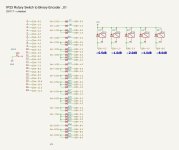
Attached is a schematic that is hopefully self-explanatory. If not: For a Pro Audio-application I want to turn a Rotary Switch (1P23) into an encoder, to switch 5 "Bits" (Relays) in different combinations. The relays control simple attenuators in front of an inverted OP-Amp. The "Bits" 0.5dB, 1dB, 2dB, 4dB and 8dB, which would enable attenuation down to 15.5dB - more than enough for my case. I want a mechanically fixed amount of steps, 23 would be perfect, positions of the Steps/Attenuation-Values must be fixed for recall. I want to avoid any MCU/...
So far, I tested a small portion of the concept and it worked, yet I couldn't find much info on this, and maybe I'm just trying to re-invent the wheel. I'd very interested on input on this approach. Considerations, oversights, different approaches to the Rotary Switch-to-Binary-Encoder-topic. Better solutions, different solutions ... I thought about CMOS-ICs and even AD-converters, but this here was the most simplistic version, I could come up with. I'm aware of encoders, but most of them either have only 4bits (= 16 positions. I need more) and/or are endless, which is not suitable for my case (see above).
The concept is based on the RelaiXedPassive
For the diodes, I plan to use Diode Arrays (8 indpendent 1N4148 in 16-SOIC: S16-4148E3/TR7). Relays are Omron G6K, 5v. Voltage drop with 1N4148 seems to be in the tolerance of the G6K, worst case I beef up the Power Supply to compensate.
Thank you for your input!
Cheers. Tim
I'm honestly not sure if I used the right terms, but hey, ... maybe I'll learn even more.
Attached is a schematic that is hopefully self-explanatory. If not: For a Pro Audio-application I want to turn a Rotary Switch (1P23) into an encoder, to switch 5 "Bits" (Relays) in different combinations. The relays control simple attenuators in front of an inverted OP-Amp. The "Bits" 0.5dB, 1dB, 2dB, 4dB and 8dB, which would enable attenuation down to 15.5dB - more than enough for my case. I want a mechanically fixed amount of steps, 23 would be perfect, positions of the Steps/Attenuation-Values must be fixed for recall. I want to avoid any MCU/...
So far, I tested a small portion of the concept and it worked, yet I couldn't find much info on this, and maybe I'm just trying to re-invent the wheel. I'd very interested on input on this approach. Considerations, oversights, different approaches to the Rotary Switch-to-Binary-Encoder-topic. Better solutions, different solutions ... I thought about CMOS-ICs and even AD-converters, but this here was the most simplistic version, I could come up with. I'm aware of encoders, but most of them either have only 4bits (= 16 positions. I need more) and/or are endless, which is not suitable for my case (see above).
The concept is based on the RelaiXedPassive
For the diodes, I plan to use Diode Arrays (8 indpendent 1N4148 in 16-SOIC: S16-4148E3/TR7). Relays are Omron G6K, 5v. Voltage drop with 1N4148 seems to be in the tolerance of the G6K, worst case I beef up the Power Supply to compensate.
Thank you for your input!
Cheers. Tim
Attachments
Seems fine, although there may be an ancient 74xx device that does this it probably only has 16 inputs and would be unobtainium now.
The other approach is a microcontroller. You'd string the switch contacts as a long resistor chain and feed the wiper to the on-chip ADC to figure out the code and drive the 5 outputs - only 6 I/O pins needed for the microcontroller so can be quite compact, and the switch can be remote from the PCB..
The other approach is a microcontroller. You'd string the switch contacts as a long resistor chain and feed the wiper to the on-chip ADC to figure out the code and drive the 5 outputs - only 6 I/O pins needed for the microcontroller so can be quite compact, and the switch can be remote from the PCB..

Thank you Mark! That's actually great to hear. I felt a bit like re-inventing the wheel, knowing sth like this must have been done before microcontrollers and even CMOS. I never worked with logic ICs and diode matrices so far. So I was (and am) curious, how ancient my approach is 😉
I considered a microcontroller, but I would like to avoid to deal with programming that, if it doesn't have some greater benefits. Yet, I will keep it in mind, thanks for the input!
I considered a microcontroller, but I would like to avoid to deal with programming that, if it doesn't have some greater benefits. Yet, I will keep it in mind, thanks for the input!
The CD4532 is a CMOS priority encoder, it is still active and it is cascadable:
https://www.ti.com/lit/ds/symlink/c...=https%3A%2F%2Fwww.ti.com%2Fproduct%2FCD4532B
https://www.ti.com/lit/ds/symlink/c...=https%3A%2F%2Fwww.ti.com%2Fproduct%2FCD4532B
@Elvee, thank you, this looks very promising! I will get a couple of those and start to try them.
@benb, thank you as well for the input! I couldn't wrap my head around, how this would be implement in my case - but as a theoretical input it is highly interesting and appreciated. I'm learning a lot about encoding right now!
@benb, thank you as well for the input! I couldn't wrap my head around, how this would be implement in my case - but as a theoretical input it is highly interesting and appreciated. I'm learning a lot about encoding right now!