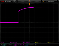
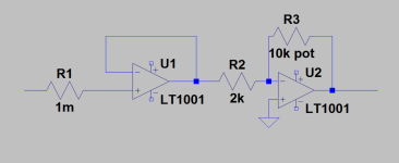
Simple high impedance buffer to fractional gain boost circuit. I've used the NE5532 as well as the LM4562 chips. When input is connected, circuit works as it should. When I un-short the input for example, the scope capture is what happens. The supply is an unregulated +/- 12V and you can see that the voltage on the output goes to 16 and reduces the negative rail accordingly.
When the pot is reduced to minimum, the output returns to 0V in relation to the pot setting. When the input is shorted again, the output drops back to 0V. I have not noticed any oscillation with either chip.
I don't understand why with no input, it throws off the balance of the rails. So if I have 2 channels of this same circuit connected to the same supply and I give one of the channels an input while the other one isn't fed anything, it will throw off the balance of the supply. This is no good. Any help in understanding this better or advice on how to stabilize this problem would be appreciated.
Attachments
Another clue, I tried a OPA2134 and the output swung to about 4.6V at max with no input and didn't throw the rails off balance. Something to do with input current then?
U1 + input must be ground referenced. You can not leave any opamp input floating in a real circuit.
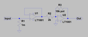
Thank you for putting me on the right track Mooly. This is for a high impedance instrument input, that's why it needs to be disconnected periodically and it's important that it's output behaves. The first time I built this, I put the 1M R1 in there (sorry I drew it wrong on the OP, in series). -See attachedU1 + input must be ground referenced. You can not leave any opamp input floating in a real circuit.
This time I thought that I could omit it and just use the + input's high impedance without adding resistor noise. After you putting me back on track, I've read a lot about it and now when I add R1, it fixes the problem. But am I wrong in thinking that this will add noise or is does that only apply to high values of resistance on the feedback path?
Attachments
The 1 meg will add noise when nothing is connected to the input but that noise value is instantly shunted by the output impedance of whatever device you connect to the input.
One very real issue is that real opamps like the 5532 have a relatively high 'input bias current'. This is a small DC current that flows out of the input pin and through the 1meg to ground. Although small it develops a voltage at the input pin and that voltage would be passed down the line as offset.
It can be eliminated by keeping the DC resistance equal at both inputs which in this case would mean adding a 1meg in the feedback to the - input but you can't do that here because that would cause other issues of noise and low bandwidth.
So your circuit above should include an input coupling cap and AC coupling between stages or use a FET opamp which has almost zero input bias current and offset. The 5532 is one of the worst for highish input current (and so offset), the 4562 is magnitudes lowers.
Try it. If you use a 5532 you will see a significant DC voltage at the opamp output with that 1 meg.
Yes I'd suggest this is definitely an application for a FET input opamp, then you can use 10M bias resistor even! Audio connections should normally be AC-coupled anyway, so DC-bias paths are not reliant on what's connected, and DC-offsets don't build up. Its good to have RF suppression at the input too, so 100pF to ground directly at the connector (ceramic) would be strongly advised, unless the source is very high impedance indeed - what is it?
R1 is 1 milliohm - do you realize? If it were 1 megaohm ("1Meg" in Spice), you'd have an enourmous source of noise at the input, which is very bad news - minimize series resistance on an input, it creates noise.
If you used a single non-inverting amplifier stage you'd have a simpler circuit, but this forces gain to be unity or greater.
- Home
- Source & Line
- Analog Line Level
- No Input on Line Booster Sends Output to Full Swing...


