Sansui SR-212 Antiskate Weight.

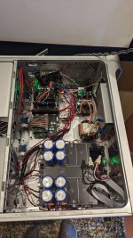
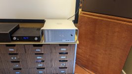
I came across this dusty Sansui turntable in my sister's shed, it's been sitting there for a long time. After giving it a clean-up, I noticed the anti-skate weight was missing. Does anyone happen to know how much the actual weight itself weighs just to make sure I get the right one? I've checked the service manual but no luck there! Any help will be muchly appreciated.

Designing an AC current limiter for inrush current limiting

Hi all, I have some inrush current issues with my amplifier - mainly because of large filter capacitors up to 22mF*2, and that creates a current surge from my mains (no breaker popped yet, but lights will dim). I know there are solutions such as NTC resistor, time relay delayed circuit, or a MOSFET soft start (as mentioned in https://sound-au.com/articles/soft-start.htm). But I suddenly wanted to make a universal external current limiter that you can plug between the mains and your amplifier and it solves all the inrush problems.

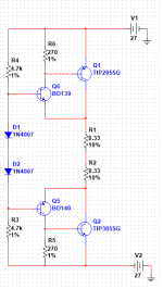
Having been working on current limiter for regulators, I came up with this schematic:
AC current limiter.png

It's basically a MOSFET current regulator circuit, but doubled for AC. During the start, a small current through D2 and R3 (and the MOSFET body diode) will charge up C1 and C2, and Q1 and Q4 starts to conduct until they are fully on (very small Ron). The load will only see R2 in series. If the current through R2 rises above a threshold, the voltage across R2 will turn on either Q2 or Q3, and it discharges C2 or C3, thus turn off Q1 or Q4 slightly until the current is no longer above the threshold. The threshold should be Vbe/R2, so if R2=0.33ohm the current will be limited to around 0.7V/0.33ohm=2.1A. No larger inrush current anymore.

I haven't built the circuit yet because it requires working on lethal mains voltages, and I think it's better to have others to check the idea before handing on. If you find any faults or improper parts in the schematic, or you have better solutions to this problem, I need your advice! Thanks a lot.

What's a good 5" mid-bass for vocals?

A totally subjective question which anticipates answers like "it depends on the cabinet and crossover" etc. But nevertheless, can you guys point me to some good 5" units for vocals. I'm a musician and songwriter and listen mostly to vocal music.

I'd like in particular to get some opinions on the cone material. So far I prefer coated paper to aluminium (Alpairs) but no knowledge of aerogel, carbon fibre, kevlar, plastics etc. Looking for a sound that is fairly full and not skinny, while retaining good detail.

I propose to use a hollow concrete block enclosure 440x215x215mm which should be adequately rigid and dead.

Any opinions and experiences gratefully received.

Schematics and service manual for Krell FB250M

Can someone send me a copy of the schematics service manual, one amp gets very hot and shuts itself down, led goes out at power up another issue. my tech needs the schematic to bias the faulty amp. I and tech hunted for this info but couldn't find anything at all, like bias voltage and offset voltage.....etc. another tech(but he's away for holiday, tired/ overworked) also said amps looks pristine and caps are healthy, was thinking of recapping too, is doing so good?

Munich 2023 Feedback

https://parttimeaudiophile.com/2023/05/22/phasemation-yukiseimitsu-wolf-von-langa-munich-2023/?amp
From Marc Philips

Marc Thank you for your kind words..

Wow! That's a pretty good complement!

Phasemation was also introducing their new flagship PP-5000 cartridge, which had an overall sound that was unbelievably precise and confident in the groove. The entire system, however, had a unique soundstage that reminded me of the first time I heard a VK Music system featuring Sunvalley amplification, AER speakers and a Sparkler Audio CD player. It’s a sound that pulls you inward until you’re immersed in an otherworldly and vaguely spherical image that informs you of everything that’s happening within the music.

DIY is my passion... Good Quality and Afforable..

Seas T35. Alnico vs Neodymium

Hey guys
i found the tweeter for my next project, the seas t35
now theres the alnico magnet and neo magnet

anyone had the chance to hear both?
if not, any though on which i should go for?

https://www.madisoundspeakerstore.c...-exotic-t35-x3-06-tweeter-with-alnico-magnet/

https://www.madisoundspeakerstore.com/seas-soft-dome-tweeters/seas-excel-t35c-002-35mm-mid-tweeter/

Gross volume vs. Net volume

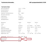
I read the datasheet of Braun LS200, or ADS L1590/2, speakers. It states two values of cabinet volume: Gross and Net volumes, as depicted in the red circle.

Translated from German, the one with 125 liters is Gross volume, while the other with 94 liters is Net volume. The enclosure of these speakers is sealed type.

What is the difference between these two values?

Attachments

  • braun-ls-200-weiche_202535.jpg
    braun-ls-200-weiche_202535.jpg
    101.8 KB · Views: 442

Contacting Microsoft

Thanks to wiping out windows on a new machine and forgetting the password on my old one i am having problems using my account with them..Unusual activity detected. Part down to trying to install a downloaded ISO when I broke the new machine. HP machine so digitally signed in rom. I thought it might work out however they had picked up that I had activated it before it was overwritten. My fault. Bad day and I didn't arrange to dual boot with linux the correct way. I also tried to install business use hoping it would get round advertising interest bloat. It knew I had used personal personal previously. LOL On this install. Seems I did use buisness install on win10. This means I now have 2 separate accounts. Same email address and no way to sort it out.

Anyway HP have sent me stuff to reinstall windows and their drivers. So yet more strange activity to come. This doesn't help me log in to my win10 on the machine I am using until this is sorted out. I have stuff on it I want to move to the new machine. I'm posting under Linux on it.

So I try their recovery method. I have reset the win10 password in the past. I don't use win very often. Now it needs 2 email addresses and one should receive a code to allow me to change the passwords. I have tried several times and waited for up to a week to receive the mail. Latest try says look in junk folder after a couple of days and mail may include a code that can be used by support via a chat line. However if no mail arrives..... So far it looks like it wont. Must be 3 weeks+ since the first attempt. They say I can use this method as often as I want with some time between attempts. Lost count of how many times I have tried it.

Microsoft list a support telephone number for the UK but it just points me at the web to use the method I have already used.

Anyone know of a method of actually talking to someone there?

HIFI JBL2206 and Compression build

I have been mulling a build with JBL 2206 drivers (probably 1/channel) and a very high quality compression driver for the top end. I have recently lost my dang mind, and too too great of an advantage on a good deal on some 2206 drivers (6 of them!!!). I will am inclined to go sealed with them, active crossovers, EQ to about 60-90Hz, picking up with probably 18" below them that I will decide details on later. My inquiry for now is the approximately 800 Hz and up territory. I am very intrigued by the N314X driver. Does the community have any thoughts about this?

Ian Canada ApplePi streamer dac build progress

I just wanted to post the project I've been working on for a bit

Source
-Pi
-Cal delta transport

Ian components as of right now
-station pi
- the big battery+cap supply
-receiver pro
-q7
-sine pi
-reclock
-dual mono dac
-opa861 I/v

Clock
-well tempered drixo 5.6

Ps
-Xbox 12v 14 amp smps for battery bank
-random ebay set up for I/v

In the future
Ucpure for I/v and q7
I have the two frequency doublers coming so that I can use the 22 for the master clock on the ess dac

Love the sound! I'm sensitive about how dacs/digital affect piano tonality and I feel like this setup does not call attention to that at all! It's really beautiful playback. The first thing that really jumped out to me as this being a different level of playback for me was listening to solo singers and hearing the dynamic swings that before or either compressed or got harsh. But the dynamics feel natural to me.


The enclosure is in my opinion a great solution. Apple put a lot of EMI. RF type features into their enclosure. The top panel comes off just by pulling out a lever so making adjustments or doing anything is really easy. It also allowed me to isolate the pi up in a separate area in the old SMPS power supply location. There's also plenty of room to do things, I will still be able to fit the rest of the frequency doublers and ucpure supplies. And better yet it was only $40.

Attachments

  • PXL_20230523_210346370.jpg
    PXL_20230523_210346370.jpg
    496.8 KB · Views: 307
  • PXL_20230523_210330255.jpg
    PXL_20230523_210330255.jpg
    369.1 KB · Views: 217
  • PXL_20230523_210402294.jpg
    PXL_20230523_210402294.jpg
    251.2 KB · Views: 189
  • PXL_20230523_211103816.jpg
    PXL_20230523_211103816.jpg
    281.9 KB · Views: 197
  • PXL_20230523_211108466.jpg
    PXL_20230523_211108466.jpg
    276.5 KB · Views: 213

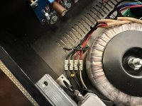
Bass amp with a burnt fan - voltage - Trace elliot AH 300

Hi,
So the fan of my amp started to smoke after I turned it on . I turned it off immediatlyj , then try again to turn it on, smoke again , so I turned it off again.
I repeat it couple of time until I thought " yeah , that fan must be well-cooked now , I'm good for getting a new one".
Changing the fan is not a big deal for me , but my worries goes about the cause of all of this. the fan is a 12 V , so I mesured the voltage on the outlet of the board ( where the fan's wire are plugged) and i mesured 81 V DC .
So my question is , is that normal ?
I don't want to burn a new fan again , so I would be very grateful if someone could help.

Improving on VRDS CMK 3,2 drive - and Copland CDA-288.

Right, so time for an update on Teac drives and updating them.

I wrote in another thread on how to insert the cd tray into a CMK 4,0 drive, that I would be trying to use a cmk 3,2 drive in my very confined spaced Copland CDA-288 Mk. II S.E.
That is now done, and it can possibly be used elsewhere 😉
So here we go:

On my two Copland CDA-288, the Mk. I and the MK. II plus it's a special S.E. model with K selected BB PCM63 dacs instead of the normal BB PCM 63P, there's the good sounding CMK 4,0 drive, but I want to obtain a better output from the drive, before it enters fintering, conversion etc. So hence the wish to build in a CMK 3,2 Teac VRDS drive into the very confined space on the Copland CDA-288 cd-player.

This should in theory give a lot of advantages:

1/: better laser, glass kss151a. Improvement 1.
2/: magnetic drives laser sledge - fast and silent, and far more precise because it's not snail or tooth driven. Improvement 2.
3/: big hall motor on the upper stable platter. Improvement 3.
4/: thick heavy cast aluminium upper stable platter. No noise from the cheap Mabuchi made in china brushed motor that bestows the CMK 4,0 drive. Improvement 4.
5/: a stable composite non-twistable upper bridge. Improvement 5.
6/: better upper bearing - larger, more precise. Improvement 6.

All this should in theory help with better output and mechanical stability/precision, which should lead to less errors and less error correction 😉

I bought (again, again, again) another VRDS-10 and used the servo board and the CMK 3,2 drive.
The connectors on the CDA-288 Mk. I and the MK: II S.E. are different in a very nice way: they became lazy at Copland in Copenhagen, and used some of the connectors directly from Teac. Well, to be honest, I don't know if they are lazy, they just did it. There could have been mechanical issues, production matters or other reasons. Anyway, it made it all the more easy to install the VRDS-10 servo board into the Copland CDA-288 Mk. II S.E. Thanks Copland! It fits right in and all connectors are ready.

The remaining connectors (most), are from the CMK 3,2 drive: laser, sensors, switches and hall bridge motor etc. Fits as well, as it all come directly from the CMK 3,2 driven VRDS-10.
So, on the Teac, the display sits below the drawer. On the Copland, it sits above the drawer. There is no way the CMK 3,2 will fit hight-wise and also in width. Hmm...
Fortunately a sanding of the underside of the lower composite plastic chassis is easy, use a mask, and it can be trimmed down.
Doing this, there are a few observation points, that have to be solved:

1/: the motor assembly that raises/lowers the lower center spindle, is mounted on to a metal bracket that is screwed down from above into the lower chassis. This make it hard to sand the chassis from below. Therefore I chose to alter the installation of said motor bracket to be as flat as possible, including cutting up threads to 4mm instead of Teac's 3mm, and use pinol stainless (un-magnetic) screws from below with a dab of 10-seconds glue to each (undoable/redoable). This solves that.

2/: the laser sledge lock mech have to be undone, by removing the white plastic tab. I will later on redo the small bracket and reinstall the laser lock tab, just in a lower, flatter version.

3/: the small flat laser cable transition pcb that sits under the lower composite chassis, have to be raised as much as possible. So I took off the standard stays and installed two new very low stays. Both 3mm screw versions. This raises the small pcb to lower the lower chassis that the whole CMK 3,2 drive can stay on 25mm stays and clear the bottom chassis plate on the Copland cDA-288 case.

4/: the next thing is to have a longer flat cable from the aforementioned laser cable pcb, to the Teac servo pcb. The standard used is 17cm long. I need at least 20cm to reach the connector on the servo pcb reliably. So I found that on fleabay. It works well, and the fresh lanes are most welcome.

On the Copland, there are welded in some 30mm stays to support the CMK 4,0 drive from underneath. The two front ones must be cut off. I then installed two lower 24mm high 3mm bolt stays on the front edge of the CMK 4,0 metal upper chassis plate and when all else was finished, I gave them a dab of strong glue and installed the drive into the Copland case, waiting 24 hours for it to cure fully. The rear one to the left side is copper and makes a ground. This and the rear to the right are cut down to 24mm and drilled out and new 3mm thread cut, to support the modified CKM 3,2 upper metal plate chassis, which have to be drilled to suit the mentioned two stay on the rear. This is done by marking them with a dab of white tusch and install. Then lift the chassis and drill the upper metal chassis plate in the two spots now marked white. Finetune the stays in relation to the installed cd tray, before making it final, so the tray is centered in the opening of the front chassis plate on the Copland CDA-288.

Next is drilling a 10mm hole to support the HDCD led on the front of the Copland CDA-288. Then the connector can easily be installed/undone.

Then the sides of the upper metal chassis plate must be cut to suit and clear the Copland power supply pcb on the left and the Teac servo pcb on the right. A couple of corners have to be trimmed as well. I retained a few mountings points from the VRDS-10 sub chassis, so all it reversible. Also, new male-female stays in brass are ready to reverse the mods on the rear stays of the Copland CDA-288.

On the lower composite chassis, there have to be done a few trimmings on the sides as well, mostly where the chassis have protrusions to support the upper bridge. They can be angled and still fit well.

Next, the rearward right side spring have to be removed. It will still function well with only 3 springs.

Lastly, the right hand side of the button control logic pcb of the Copland CDA-288 have to be trimmed down a few mm's to clear the CMK-3,2 chassis.

That's all.

Of course, I have to retrim the laser to suit, as it's been handled around and need new precision adjustment. Just follow Teac VRDS-10 service manual, and it's done.

It plays! A CMK 3,2 drive is now working in a Copland CDA-288 Mk. II S.E. and is MUCH more precise and well working. I'll report back on sound quality etc, once everything is scoped and adjusted properly again.

Next up is an über bridge to the CMK 3,2 drive, which I feel can be improved a lot.
There are a few solutions to this:

1/: Either choose one of Teac/Esoteric's own solutions.

2/: Make your own.

As Teac actually did the bridges with a lot of precision, and it's slightly curved 0,5 degree, it's difficult for me to replicate the upper stable platter. So BRIDGE it is.
The later Teac/Esoteric Neo bridges and the last old series upper bridge have a construction that I can replicate. Thais can be done as long as I retain the CMK 3,2 upper platter as this has a certain weight and dimension.

Improvement 7:

I took the upper CMK 3,2 bridge apart and kept the hall (sony) motor coils as they are important. N need for voltage and amp changes then.
I then measured up the CMK 3,2 upper composite bridge and it's important dimensions: inner height to coils, spacing, drillings etc. A friend is now making a fat heavy stable aluminium one for me. It's only reinstalling the upper platter and the platter brake, and reinstall on to CMK 3,2 drive.

Improvement 8:
I also feel that the upper bearing which is a plastic grey cap and a dab of grease, can be improved. Note: the tightening of the upper 3 screws can determine the brake and resistance.
So, I made a design for a better top bearing, which uses a square top cap in metal and a bore that supports a ceramic ball. Less wear and more precision and less contact area to the spindle/top bearing relation. A ceramic ball is more round and wear less.

We'll see.

Improvement 9:
Green light has a dominant wavelength of 495-570 nm, and the Sony KSS-151a laser works at 781 nm. Hmm. Helpful? Let's try it. Green it is. So I want the upper platter to be green on the underside/cd side, to retain stray light or rather prevent the light that is not into a pit, be less seen and which is now out of phase and help the laser do a clean job. Less errors - less jitter. If one believes that.
I then wanted the Teac CMK 3,2 upper platter to be anodised green, but this led to a series of problems.
First, I looked at the metal composition of the VRDS CMK 3,2 upper cast aluminium platter, and it turns out to be involving a very high content of zink. As zink in this respect cannot take anodising, as I was told by two companies whom I contacted, I had to find another solution.
Painting is going to be worn off, so that is no good either and will also represent a whole problem in itself from a perfect flat surface perspective. No can do.

Traveling through every single VRDS drive ever made, some of the upper tiers are in fact green un the underside of the upper platter. Hey presto, get one of those. But they are not for sale. And to buy a Esoteric P2s just to use the upper platter is maybe taking it a bit far... Same goes for Teac P-70 drive. Same goes for Wadia 861SE which had an upgrade from CMK 3,2 to CMK 3,2s, also called Superdrive.

But hey, it happened to be so, that Wadia worked with Teac over a number of years, developing some of their pcb's and used some of their drives as we all know. But on The Wadia 861, one could order a Wadia performed upgrade to the drive itself. It was a 2500 usd option.. Mglp! It consisted of some vibration dampening cut to fit pieces of stick on material on for example the inside of the outer case, the upper metal CMK 3,2 chassis plate and more. And the other major difference, was the Superdrive! Hey, so there was originally a chance to get a Superdrive bridge and upper platter by order. As Wadia no longer exists, I had to scan the www to find one. And I did. This green upper platter is exactly what I was looking for, solving what I wanted to obtain nm wise.

Improvement 10:
I wan to obtain more stable rotational speed. On say a car engine, there is a flywheel. This acts as a stabiliser to the engine, so torque is retained better than with a light flywheel, which makes the engine pick up rotational speed faster. The exact same thing is the case with the CMK drive in our VRDS-drive cd-player. So I want more mass. I cannot make this myself though. But it would be nice to have, to obtain and keep a far more stable rotation in the rpm's that a red book reading does. More mass brings rotational stability.
On the Superdrive CMK 3,2s, is a far better upper plate in relation to stability. It is a better cnc made platter, rather than a cast low quality aluminium/zink thing. And it is heavier. Like on the CEC belt driven thing, the belt is not the only smart part. Rather the mass of the puck. Same here.
To improve on matters, Teac also made better magnets and an improved bearing, plus a stronger hall motor. I got what I wished to improve on.

Improvement 11:
On that Superdrive, there is a far bigger more stable well executed upper bridge and it will absorb and prevent vibrations from doing harm. More later.

Improvement 12:
On all my cd-players, there’s light from the outside slipping in through the load cd tray’s opening. I looked at Apple Mac Pro cabinet’s loading mec and unfortunately I couldn’t make it fit. It has a smart little door that closes the front opening so no light is entering. I will experiment with more solutions onwards. To prevent unwanted light from disturbing the cd reading. And Teac removed that window on the VRDS10se. And it came back later on, in form of Neo driven multi players…

Improvement 13:
Clock.
As with all things, matters can usually be improved and the clocks that Teac/Esoteric used in the old players, there are certainly things to be done. I installed an LClock XO and a separate power supply to avoid any transfer and get a precise stable clock.
Now, some years later, I want to get an even better clock, and lo and behold Larsen Audio made another much better version: LClock XO3, which have better shielding, lower ppm's (now 1!), and other improvements. Same power supply can be sued, so I'll do that, unless of course, I find a better one still.

Improvement 14:
Capacitors.
I unsoldered the two most important ones in the signal path in the output stage and soldered in two bigger ones from Jantzen audio. It did take some hours to make them fully sing, but that made an improvement.

Improvement 15:
Chassis dampening.
To kill any unwanted vibrations, i cut a lot of bitumen sheets to fit inside the casing. I will improve on matters when I find something suitable thin for the upper chassis metal plate for the CMK 3,2 drive and it should work on the CMK 4,0 plate as well. More on that later.

Add: Well, I also now got a complete bridge and upper platter from a Esoteric P2s (not the P2). and the bridge is all metal (stiff) and the platter is cut aluminium with bronze inlay (heavy stable flywheel), and the underside is... green 😉 That will go into my other Copland CDA-288 with yet another VRDS-10 servo board and CMK 3,2 drive.

So far so good, and I'll be back with more later on.
Kind regards,
Redfox.
TV Vertical Outputs for Audio Use

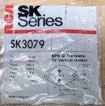
I have a set of four old SK 3079 outputs that I wanted to use in a Dynaco Stereo 120 I'm redoing. But I see that they're TV vertical outputs, and from the info I've been able to find so far, it seems that these aren't good for audio use due to not being very linear, among other issues. I'm fine with using something else, but I wanted some other takes before I trash these.

Attachments

  • SK Vertical Outputs.jpg
    SK Vertical Outputs.jpg
    408 KB · Views: 101

Large Fiberglass Horn?

Mostly to satisfy my curiosity at this point; I'm still a long way from actually building one.

I've thought for a while about a true-full-range, single-point-source PA speaker, that can produce comparable volume to a modern concert, and actually use it as such. Say, within 1dB of flat between 30Hz and 15kHz, and 140dBA continuous at 3 feet, measured with pink noise, all from a single acoustic point.
And enough directional control to not feed back easily to the stage mics. Say, 90deg absolute max for that, at 200Hz (high-ish highpass for vocals), which dictates a radiator size of almost 5 feet. (Keele's Constant)
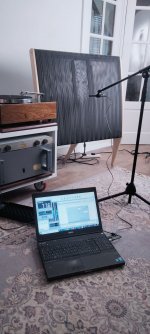
The original idea was to make it easily portable - unload from the truck and set up at least two of them in no more than 10 minutes total, with no local infrastructure at all - while keeping that performance. But those are massively conflicting requirements!

I keep coming back to a horn design, specifically a multiple-entry horn to easily satisfy the "single acoustic point", with sealed-back drivers and a DSP to manage it all. But a horn would have to be about 10 feet long to comfortably support 30Hz. (it can be folded, but the total length through all the folds must be at least that) Building it out of 1/2" or 3/4" cabinet grade plywood would almost require straight sides, to avoid the headaches of bending (thick) wood, and then a coverage angle between 45 and 90deg would dictate a 5 to 10 foot mouth, not to mention the weight of all that solid plywood! And any homogeneous span of that size and relatively small thickness would still have panel resonances that need to be damped.

To try and get some portability back, the overall dimensions can be modified using hinges or disassembly, which also create possible places to rattle, and doesn't help the weight at all.

Then I got to thinking, "What about fiberglass-covered foam?" I remember doing that in a high school robotics program, with 1" insulation foam and fiberglass fabric, to make a robot arm that was easily more than strong and stiff enough for what we needed and barely weighed anything. A single panel wouldn't even have to be a single sheet either. It could be "boards" of 'glass-wrapped foam that are then "glued" together with more fiberglass, which creates an internal brace at the edge of each "board". And these "boards" don't even have to be straight or uniform, just as long as they fit together. If it ends up with internal braces (edges of pieces) going every which way, that might actually be a good thing for acoustic stiffness. All that really matters is that the acoustic surface doesn't move appreciably at any audible frequency.

If that solves the weight problem without creating resonances, then the portability part becomes less constrained...

And it might also be easier to create curves that way too, like for a folded exponential horn instead of a strictly-straight one...though that would make it harder to pack into a small truck with other gear...

Thoughts?

Help with unknown mixing console

Hi.
I posted the same question on probably wrong subforum.
Let's try on this one, maybe I will have more luck here 🙂
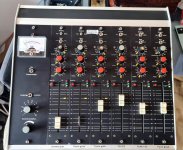
Recently I got this small old mixing console.
It has 6 channels with Haufe mic input transformers and Alps faders.
It is probably made in Germany in late '80' or early '90
Anybody recognize this consile and is it worth to use.
Thank you in advance!

Attachments

  • 20230520_115703.jpg
    20230520_115703.jpg
    113.8 KB · Views: 125
  • 20230520_120108.jpg
    20230520_120108.jpg
    185.5 KB · Views: 124
  • 20230520_121456.jpg
    20230520_121456.jpg
    183.9 KB · Views: 131
  • 20230520_125445.jpg
    20230520_125445.jpg
    77.4 KB · Views: 132
  • 20230520_125452.jpg
    20230520_125452.jpg
    104.3 KB · Views: 126

Best DIY Bluetooth transmitter chip with APTX?

Looking for the right microchip for an electronics project. I have multiple questions regarding this, but first some background on the application:

I have an electronics project which needs to be able to receive a Bluetooth audio signal as well as retransmit the same audio signal to a separate Bluetooth connected speaker. The circuit I'm building is meant to operate as a middle man, and I'm trying to maintain as good of a signal quality as possible throughout this chain. (Latency is not much of a concern, my circuit only reads audio signal for visual effects, no audio output).

To accomplish this, I intend to use 2 Bluetooth modules on my board, one for receiving the audio signal from the source (eg, smartphone), and a separate one for transmitting the recieved signal to a paired sink (bt speaker). The 2 chips will work together to hand off the signal from reciever to transmitter.

I need to know which Bluetooth chips will allow me to recieve aptx audio and which chips can encode and transmit audio in aptx formats, as these are some of the most commonly supported hi-fidelity wireless audio transmission types. I don't mind having different chips for receiving, transmission, and encoding/decoding if necessary, but I am looking for the easiest/simplest setup to work with.

I have seen a variety of Qualcomm chips which seem to support some of these features, but most are marketed as Bluetooth receivers and I'm wondering if they work just fine as transmitters as well. Ive seen qcc3034, 3008, 5125, 5144, 3040, etc...modules with a variety of different capabilities.

I have also read that I2S support will allow a digital signal to be transmitted between chips, avoiding the DAC to ADC signal path. This would be ideal

My questions are:

1. Which Bluetooth chips allow for transmitting an aptx audio signal from an analog input?

2. Which Bluetooth modules support I2S signaling (input and output)?

3. What kind of software/ resources are needed to work on these chips?

4. Any other notes or advice is appreciated.

Cheers

Cheating when the wife leaves

Wife went to see her family in the Philippines for 3 weeks. What to do, what to do. Race home from the airport, throw pillows around, hang some clothes up, and listen to the results, that's what! Yes, this actually gets ugly for real, but I have never heard G olden Earring jump off the wall, live in front of me like this in all of my years.

Try it. Take a chance. Ok, so gobsmaked applies here.

Attachments

  • P5180003.JPG
    P5180003.JPG
    368.3 KB · Views: 417

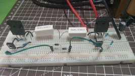
Want to confirm that these transistors will work in this circuit

This is probably a very easy question and I’m 99% sure I know the answer, but my brain isn’t allowing my to move forward without confirmation.

I have this circuit where I need to replace a 2SA839 and 2SC1669
IMG_6541.jpeg

IMG_6542.jpeg


Generally the recommended replacements are MJE15032g and MJE15033g and they’re definitely overkill for the job. I have plenty of the 15032/15033 transistors on hand, because of an ordering mistake that I made I have 3-4 lifetimes worth of TIP41C and TIP42C, so I’m trying to use them wherever possible.

I understand why the TIP devices are not usually recommended as a replacement because of the lower Vce and Vcb, but that’s of course circuit dependent. The TIP devices exceed the specs of the originals in every way except for the Vce and Vcb, being rated at 100v for each.

With the voltages being all the same polarity for each transistor the TIP devices should easily handle this circuit correct? With the collector to base voltage being around 13.5v and the collector to emitter voltage being around 14v. My brain is says “duh, you know this” while at the same time “maybe you should confirm”.

Thank you,
Dan

Albarry PP1 right channel inoperative

Hello - I recently bought a nice pair of Celestion A compacts which I hooked up to my beloved PP1. Unfortunately, the right speaker had a defective crossover which took out the right channel of the amp. A small wisp of smoke appeared somewhere near the vent holes in the lid, sort of near the middle of the circuit board (the right channel circuitry is towards the rear - I picked up that much!)
Anybody got any experience with these or at least has a coupel of suggestions? I can solder if told what to do, but fault finding with amps is above my pay grade! 🙂
IMG_0976[1].JPG

Battery strategy for busking amp using 18650s?

Hi all, I am working on a DIY busking amp (thread here), and have settled on the following specs:
18cm x 26cm x 30cm wooden cabinet
B&C 6XT13 speaker
TPA3116 amp (starting with TDA2050 until I get the TPA3116)

I would like to be able to play the violin outside for a crowd of 20 people in a city center for two hours.

Which batteries should I use? I was thinking of using an 18 5Ah drill battery...but...

Then I thought of making my own 14.8V battery pack with a BMS and four 18650 cells inside the amp, and using a power supply (like a laptop power supply) to charge them.

Would four 18650's (with the protective chips) be enough for my use case ?
Is it safe enough to charge them with a charger?

Any advice much appreciated ! Thanks.

FS: A set of parts for 2 β24 boards including custom toroidal transformers by Primrose Audio Design

FS: A set of parts for 2 channel dual-mono β24 including custom toroidal transformers by Primrose Audio Design [300VA 30V+30V, 15VA 35V+35V]
  • 2x toroidal transformers (Primary(342VA): 2x 171 VA, Iac[A] 1.55, Secondary: 2x 30V off-load: 32.40 Iac[A] 5.0 at 150VA each, 2x35V off-load 37.20 Iac[A] 0.22 at 8VA each)
  • 2x β24 PCB with all parts for PCBs
  • 2x Parts for unregulated PSU
  • 2x σ22 PCBs and BOM parts.
Please PM.

Attachments

Onkyo Integra A8015 Integrated Amp Lights

My sons Onkyo Integra A8015 integrated amplifier was having some switch problems so I put deoxit to work on all the switches and it seems to work fine at the moment. I noticed though that two of the signal lights have gone out, one at the power switch which is yellow and another green one on the tuner input. Can anyone tell me where I might find some replacement lights, probably have to be LED lights these days, if you know the voltage I would need. I suppose the color isn't important but I thought if it were an easy fix, I could solder them in before reassembly. I am actually surprised how nice this amplifier sounds. Thank you for any help you might offer. I like to fix things but am not very good at electronic repair per se.

SMD flux

Hey,
I’m looking for a flux for smd components. I looked on you tube for some ideas and wanted to ask here. I can’t believe how expensive some are. I hate to squeak too loud but the most important thing is ease of use and clean up. I won’t be doing alot of smd but I like to leave the board really clean. Anyway, what are you using?
Thanks

4 in 8 out DSP using ADAU1652

After good experience with development og DSP boards using ADAU1701 and using SigmaStudio for programming, I plan to take it a step further.
My plan is to make a board which can take up to 4 inputs and have 8 outputs.
This would be usable for specially a 3 to 4 way or a 4 channel amp. So actually I don't really need the 8 outputs, but it just seems codecs with 4 inputs also comes with many outputs.
Secondly I want it to relatively cheap to have manufactured.
I have with great success been using JLCPCB and their assembly service. Hand soldering DSPs and ADC/DACs is not that easy.
So it needs to be using components which are available at JLCPCB!

I you want a bit more DSP power, ADAU1452 seems a good bet. The same DSP is used in the freeDSP-aurora, so should be able to get some ideas from that.

For the CODEC I had my eyes on CS42448 , which promises -95 db THD+N in a single ended mode and - 98 db differential. It has 6 in puts and 8 outputs, and has what they call popguard technology to minimize pop noice at start up / close down.
But it does not really seem to be available anywhere.

Best bet seems to the the AD1939 which has 4 in, 8 out and delivers -94 db in differential mode, and is available at JLCPCB

Any other good ideas?

For optimal performance it is probably necessary to use active and differential filters on both input and output. This means 1 opamp for output and 2 opamps for input => 8 dual opamps.
I would like to be able to run it at +5V, so will need rail to rail opamps. OPA1642 is an inexpensive, but very high performance dual opamp at less than 3€ a piece.
Maybe I could use the DRV623 as output filter, eliminating the need for a muting circuit, but the THD performance is not as good as e.g. OPA1642 .... will that really matter?!

Programming should be via Wondom ICP (as this is what I have and as the connection is smaller then the USBi) and it only 20 USD.


I was considering whether to allow to balanced input, but not sure how to make an easy input circuit to allow for that and single ended without adding switches .... any good suggestions?

Power would be LM2596 (maybe as a finished module) + a number of LM317

Preamp Question

I built the preamp from Franks Ultimate Preamp thread and it sounds really good. https://www.diyaudio.com/community/threads/franks-ultimate-tube-preamp.12042/page-4s. Not sure how to link to that thread but I'll attach the schematic. Anyway, I tried something different and I used a 12 VDC external power supply with an 8-32V to 45-390V DC-DC High Voltage Boost Converter ZVS Step-up Booster Module to get 310V and filtered really well (4 stages). I also used an LM317 to get the 6.3 volts for the heaters.

At the risk of starting a thread debating the merits of my approach (which I am trying for fun), I have a question about grounding. I use a star ground tieing everything back to the 12VDC common. The system is super quiet and works as long as all the items connected to it are powered through the same power strip. If I connect something from a different AC source even if it is connected to the other plug in the same duplex receptacle I have a high-frequency buzz and some other noise on the system. As an example I have a Volumio connected to a DAC and if it is connected to the same power strip as the preamp it works great. If I connect it to another power strip connected to the same plug sounds like I have a ground loop.

I don't have experience with DC circuits without a tie to AC ground in the same box. Am I grounding this correctly tieing everything to 12 VDC common? The chassis is connected too. Any advice?

Etching PCB's question

Hi
I've got some second hand Jensen transformers & fired up free Eagle version and made a small PCB to test them.

I'm using the PCB toner transfer method and mixed two parts of Muriatic acid with 1 part of peroxid, but it isn't etching the copper, or it is working but very slow. I waited one our and still much copper on board.
I remember having done the same some long time ago for other PCB's and as soon as I added the PCB the solution started to bubble and it was a fast procedure. If I used a brush or a finger to rub, it was also faster.
Funny is if I try it with a nail or a wood screw, it starts to bubble and etches it.
I also remember the peroxid used before was of strong industrial type like 100 or 1000%
The acid used is probably OK since I use it to clean rust on ceramic tiles.

What am I missing ?
The peroxid was sitting too long and has loosen the strength ?
Does it also work with ordinary 3-5% drug store or pharmacy peroxid ?

Thank You.

Project: Can I get close to Neumann KH 150 without dropping $3.5K

Recently saw the review for the Neumann KH 150s over on ASR and it impressed me with just how technically strong a 2 way can be with DSP implementation at its core, and it got me thinking, can a DIYer get to that level without spending MSRP of $3500 USD? I've seen the measurements for the March Audio Sointuva as a passive speaker, really elite, and that got me inspired to see if a DSP version of that can, in theory, match the KH 150 as a benchmark.

I'm going to treat this like an executable project, even if I don't go all the way and finish, which means deciding on parts, prices, cabinets, amps, DSP software, bracing, since all of that comes with the sticker price of the KH 150. We'll save the really hard part for later on, (measurements for the XO, in-room adjustments, near-field).

Some considerations, I think the KH 150s are all around solid, but I wouldn't call them beautiful per se. Beautiful to me is the Purifi 2 way Joachim Gerhard released a few years ago, see here: link. I really, really love walnut, so I'm immediately leaning towards a walnut baffle even though this might cause pains in the future for resonance. Another pain point, I'm thinking maybe I don't want to rebuild a cabinet every few years if I want to swap out drivers, maybe I like the idea of removing the baffle and driver swapping. This would be huge down the line for flexibility, and it means that in theory, I can do a sealed box, a passive radiator box, or a ported box in the future if I simply also swap the back baffle. So front and back removable walnut baffles, with Purifi at the core to start? Seems reasonable enough...

The next consideration is the tweeter, and this is where the budget of the DIY operation gets tough, since the Purifi woofers and passive radiators already are pushing $1300. I think it just makes sense to go with a waveguide based tweeter like the KH 150 and the Sointuva, helps with directivity, alignment, and I like the aesthetics. Thanks to the work of augerpro, there are some tweeters that are available with a WG, like the Bliesma 25 and 34 ($$$$$) but the tried and true DXT from the ASR Directiva also works.

I'm no CAD wizard but I quickly whipped up my idea of a beautiful walnut baffle, which used 3/4" roundovers, chamfered woofer cutout on the back, waveguide cutout on the front, holes for 5mm t-nuts on the back to mount to a sturdy box and allow the baffle to be removed and swapped down the line. The back will be identical except the cutouts will be sized for 2 Purifi passive radiators and four binding posts at the very bottom. Simple enough, nothing crazy, would like to use a CNC to machine to walnut since one of my hands is no longer working. Baffle is 220mm wide, 418mm tall, 20mm deep.

This leaves the issue of a box, which probably has me the most worried in Phase 1. I've been reading multiple threads here, reading up on somasonus, looking at what KEF, Ascend, do for their boxes and right now I'm leaning towards a 6 sixed box made of vertical 3 ply bamboo 20mm thick, primarily because of Ascend Acoustics, and using CLD KEF bracing for the interior. I have an idea of what that would look like in reality, but I'm drawing a blank on what kind of glue, acoustic damping, resonance combatting I'd need to do to deal with walnut baffles.

Step 1: Part Selection - $1450 spent/$2800 total budget
Woofer: Pair of Purifi 6.5" $860 (already owned)
Passive Radiators: 4 Purifi PRs $460 (2/4 owned)
Tweeters: Undecided + Waveguide
DSP: MiniDSP 2x4HD $225 (already owned)
Amplifier: Undecided Class D
Cabinet Materials: Black Walnut lumber, vertical carbonized bamboo ply, CLD damping

Step 2: Cabinet Making
Cabinet: 3-Ply Verticall Carbonized Bamboo 30mm "Box"
Baffles: 25mm Black Walnut Lumber with Rubio Monocoat Finish
Bracing: Augerpro CLD 90% Overlap with Weicon Adhesive, Resonix applied to inner Panels
Miter: Traditional 45 degree, perhaps with 6.35mm Roundover on edges
Removable Baffles via Bamboo L-bracket glued to rear of baffle and then screwed into panel of bamboo via driver holes?

Cabinet v1.png


Baffle v1.png


As of right now, it's actually the "inner cabinet" that has me the most worried. With the front and back walnut portions being removable, I can swap them in the future if need be, but I need to make the inner core be the foundation and be the permanent structure going forward. I am not sure if the bamboo is a good idea, I'm not sure how much it'll cost, and I'm not sure how to brace and damp it. Being one-handed, these issues need to be ironed out before getting too far ahead, since I can't really go into a workshop and experiment myself anymore. The DIYers here have been doing this for years, please chime in while the passive radiators are on order, tweeter selection is still up for grabs too.

I can always say eff it and sell the drivers I do have and just buy the KH 150's, but I'd like to give this a shot.
  • Like
Reactions: behappybevegan

Kirishima medicine for BLH bug?

Having just finished the build of a pair of Dallas 2s (but just starting the tweaking) I'm finding myself tempted to build something else. I'm liking the sound of the Dallas 2 already so cast my eye over the Woden Kirishima. Space and WAF are not a problem!

Although bigger, the construction of Kirishima looks much easier than Dallas 2 as it's all straight lines. The build effort looks much the same for Kongo and Haruna so unless there's a really good reason it looks like the Kirishima is the preferred option.

But my concern is availability of the FE206En which was quite a problem even a year ago. I've seen that @Scottmoose is adamant that this is the driver Kirishima was designed for. I don't think I can run to FE208EZ Sigma (plus treble "support"), and the FE206NV doesn't seem to generate a lot of enthusiasm - Scott mentioned elsewhere that "published Qt is significantly higher than the previous En" so I'm really unsure if it it is suitable, or what other options I may have. Advice gratefully received!

At the moment my amp is an EAR 859 (kit-built about 30 years ago) and I have an as yet untried Chinese JLH solid state amp. Also contemplating a DECWare Zen Kit 1 SET build if I can still get the transformers. Current listening room (my home office) is about 5.5 x 5.5 x 4m but our main living space is about 6x that area and has no hifi or even TV

Attachments

  • Dallas 2 BLH.jpeg
    Dallas 2 BLH.jpeg
    124.8 KB · Views: 184
  • Dallas 2 BLH 2.jpeg
    Dallas 2 BLH 2.jpeg
    99.2 KB · Views: 194

What do you all use for measuring active EQ circuits?

This may be a really dumb question to all you folks but...

What do you use to measure frequency response of active EQ and crossover circuits?

I have the Dayton DATS v3 and Omnimic V2 but as of recently, have been building a lot of active EQ and crossover circuits. Realized I have no way to really measure the final performance of these circuits.

What exactly is everyone using to get the nice frecuency-sweep graphs that I see in various places? Just some PC software w/ a passive "plug in" soundcard jig or something with dedicated hardware?

-Dean

For Sale 4 6H30-DR tubes in perfect state

Hi all. Same my last offer, with ECC801S TFK, I am selling my 6H30-DR quad tubes. I buyed some years ago and never were connected. I am selling because my DIY audio time is finished. These tubes were measure using a utracer 3+ (same ECC801S) with results next:

20230521_175057.jpg


20230521_174922.jpg


20230521_153123.jpg


The check of they are genuine..
20230521_175112.jpg


20230521_175116.jpg


20230521_175119.jpg


The four are equals.

Now measures

6h30_1_1.jpg


6h30_1_2.jpg


6h30_2_1.jpg


6h30_2_2.jpg


6h30_3_1.jpg


6h30_3_2.jpg


6h30_4_1.jpg


6h30_4_2.jpg


My reference for utracer

20230522_070746.jpg


Well, in this case, boxes were almost in perfect state and I break the seal for opening. Never had been connected and results with utracer are really good (I think).
Prices in the market for these are crazy and I do not want to go in this way. They cost me around 450 eur the four and this is the price I want (+shipping cost and paypal fee)
If you use this tube, maybe a unique opportunity (I do not use this tube in my audio chain)

Thank you
Best for all

Bridged chip amp to current drive

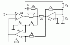
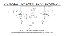
Hello, who knows to model in Spice a schematic for a bridged current drive amp?

For example for a TDA2003 amp?

Schematics here and proposition how to do it from Esa Merilainen.

https://www.diyaudio.com/community/...fication-to-current-drive.389985/post-7253904

It's possible, so why not try out?

It would be great to see it. I would try it out (build one) if I would know which parts are needed. And give feedback.

Attachments

  • bridging Esa Merilainen principle.gif
    bridging Esa Merilainen principle.gif
    4.2 KB · Views: 175
  • TDA2003 bridged schematic.png
    TDA2003 bridged schematic.png
    14.2 KB · Views: 196

Driver comparison: KEF vs. Boston Acoustics

I have an 8" KEF KAR 200B and an 8" Boston Acoustics Rally RS8 driver. I’m going to put one of them in a 1.5 cu.ft. sealed enclosure that I’ve already had. Which one is more suitable with this enclosure, please?

Boston Acoustics RS8
Fs = 34 Hz
Qes = 0.42
Qms = 2.55
Qts = 0.36
Vas = 41.0 litres
Re = 3.64
Le = 0.0
Sd = 234
Xmax = 10.2
Pe = 250 W

KEF KAR 200B (SP1330)
Fs = 35 Hz
Qts = 0.40
Vas = 50 litres
Pe = 150 W

Hakuin SE Class A HP Amp

After several years and hundreds of units of the popular Pocket Class A (PCA) headphone amplifier having been released into the wild, I thought it was time for a second version. This time though, I will name it after the 17th century Zen master Hakuin Ekaku, who popularized the koan "What is the sound of one hand [clapping]?" I think minimalism in audio can produce some of the best amps. It is this minimalist approach to the original two field effect transistors that produced a wonderful sounding amp that was unanimously liked in reviews. Now we will have an amp that uses one JFET and one BJT, together as a complementary feedback pair (CFP). Although, I love the sound of the BF862, it has been harder to find due to EOL issues. To keep things accessible, I will be using the readily available 2SK209 for the JFET and a compact DZT5401 PNP BJT in SOT223 format for good thermal dissipation. The Hakuin’s CFP topology and initial circuit was developed by Hugh Dean (AKSA), and is in my opinion, one of the best sounding headphone amps you can hear. Time will tell though as folks listen to this amp.

So we know what the sound of two FETs is, now, what is the sound of one?

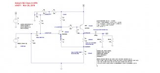
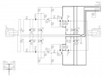
Here is the LTSpice schematic:
797819d1574800224-hakuin-se-class-hp-amp-pca-mk2-spice-schematic-jpg


The predicted harmonic profile is dominant 2nd order, with a small amount of third order distortion, and not much else. Driving 250 ohm headphones, this amp will produce a very musical, immediate presence, and with superb resolution and dynamics. I have tested it out with a BF862 and 2SA1837. Both un-obtanium, so now redoing it with easy to find parts. The overall THD will be a bit less than the previous JFET-MOSFET version.

With the help of JPS64, who put into a compact PCB, the schematic looks like this, now with some RFI filtering and in stereo:
797820d1574800479-hakuin-se-class-hp-amp-08-pca-mk2-schematic-amp-stage-jpg


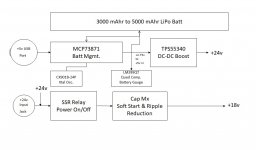
This will still be a pocket amp, but this time, we are making our own power system with LiPo batteries, a battery management system, DC-DC boost converter, SSR for power on/off, capacitance multiplier for soft ramp up to avoid pops and reduce noise, and a battery gauge meter with LEDs. Here is the block diagram (Edit - updated 11/27/19):
798122d1574922388-hakuin-se-class-hp-amp-hakuin-block-diag-v00g-jpg


Here is a calligraphy painting by Hakuin to get us into the right mindset of simplicity and the beauty of nature:
797822d1574800479-hakuin-se-class-hp-amp-10-pca-mk2-hakuin-drawing-jpg


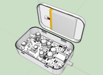
Maybe the amp will look like this, still fits in a simple Altoids mint tin - same as the orginal PCA, but with so much more value added features:
797823d1574800770-hakuin-se-class-hp-amp-06-pca-mk2-altoid-01-jpg


I would like to thank Hugh Dean and JPS64 for their help in this amp collaboration. This project really is the realization of the goal of a pure, natural sound, from a elegantly simple two transistor amp, but wrapped up in a state of the art package with the latest smart battery management and ultra quiet power supply.

Edit Jan. 14: the prototype amp is alive and songs beautifully. IAIMH helped me with the verification build and got first sound on Jan 10 and for it working on both channels on the 12th. The battery charger and DC step up now also appears to be working.

Here is the amp section on mine under first sound testing:
808216d1578737144-hakuin-se-class-hp-amp-prototype-hakuin-build-05-jpg

Attachments

  • PCA-Mk2-SPice-Schematic.jpg
    PCA-Mk2-SPice-Schematic.jpg
    188.5 KB · Views: 6,370
  • 08-PCA-Mk2-Schematic-Amp-stage.jpg
    08-PCA-Mk2-Schematic-Amp-stage.jpg
    195.6 KB · Views: 5,482
  • 09-PCA-Mk2-Block-PSU-System.jpg
    09-PCA-Mk2-Block-PSU-System.jpg
    78.7 KB · Views: 769
  • 10-PCA-Mk2-Hakuin-Drawing.jpg
    10-PCA-Mk2-Hakuin-Drawing.jpg
    66.8 KB · Views: 5,109
  • 06-PCA-Mk2-Altoid-01.jpg
    06-PCA-Mk2-Altoid-01.jpg
    251.1 KB · Views: 5,000

Adcom GFA-545 and the Cat

Just opened up a GFA-545 with a blown fuse.... Oh boy the ammonia smell is wonderful and corrosion is all over the right channel board. Yep cat pee killed the amp, well half of it anyways.... YUCK!

I started the de-population of the board and am going to replace everything that looks corroded....
From the Fuse holders to almost the other side where D601 and D603 reside. Due to the amount of scrubbing I've taken off a little bit of the silk screen.

Does anyone have a board layout that someone can actually read? The service manual is so blurry I cant use it. I'm comparing vs the schematic and i can't seem to find the disc cap 47pf that goes from D607 to R639. hmmm?

Thanks for the help,

Eric

Cone shape

What impact does the cone shape have for sound quality? This may sound strange but for midrange use a shallow cone sounds more open to me while a deeper cone sounds more shut in, it is like the soundwaves reach my ears with different shapes, i can not detect any significant in plain freq response measurements.

More edits to my retro 12" heresy & coaxial quest

Thought I just share some of my recent edits to previously posted unfinished projects after some time of little activity. I guess this is what I love about DIY, mixing up projects, endless mods and learning bringing in new ideas, enter/exit whenever time allow. For some background I have been obsessing with building retro 12" 2-way coaxials and 3-way monitors ala Tannoy/Heresy/JBL inspired stuff based on cheap PA drivers like Eminence, Fane and Celestion for half a decade now. These projects can be found here - might be interesting to some thinking about the same:
https://www.diyaudio.com/community/...-coaxial-upgrade-modification-options.359407/
https://www.diyaudio.com/community/...lestion-ftx1225-ongoing-advice-needed.377105/
https://www.diyaudio.com/community/...eded-on-midrange-options.382116/#post-7010945

The first few projects was not good, the boxes was too small and Ive struggled with crossovers and what not. The more recent projects are more successful yet I see the need to enter DSP to get any further with coaxial especially. I also struggle to make good cabinets so these are all still pilot/prototype projects until I find decent material and get/learn better tools. I do like the Celestion project still, this is in my studio to come. My last project was suppose to be a Heresy inspired 3-way construction with Fane drivers but it ended up being a two-way with surprisingly good results and has been my go-to sound for the last year or so.

Fast forward and I just bought a house with basement that I plan to build into an audio asylum. Last week I took the last Fane build and removed the bass driver (to be used in a future project with a 5" mid for a 4319 inspired monitor) and installed the Eminence Beta 12CX/PSD2002 coax combo instead from the first mod thread. The Eminence flares APS150S and APT50S are fitted with ASD1001 and APT50 drivers. Plenty of options to play around with HF but not connected as of now 😉
The EB12/PSD coax combo sounds very powerful in this box with the Eminence CX crossover. Still 2-way. Not sure what do with the disconnected HFs - maybe some supertweeter thing, I'm still working on rear ports and terminals and damping, will keep you posted about the results but finally I believe I get the max out of the Eminence drivers I bought years ago. The poplar-plywood is crappy so I might build a new box or find a way to make it better but I think they look kind of cool as well in this chabby basement as of now. I'm also surprised how dynamic it sounds with open back rear baffle removed for cutting. Maybe a dual 18" OB sub is the next project for this basement?

Hope the random thread are of some interest. Ideas are welcomed 🙂
Oh and if someone know how to remove the "Fane equiped" stamp without ruining the MDF paint please advice as this is just wrong now, this is a pure Eminence atm 😉

Eminence Heresy 1.jpg
Eminence Heresy 2.jpg
Eminence Heresy 3.jpg
  • Like
Reactions: krivium

AF GB15 Tweeter - Capacitor uF?

Hello,

Im an old hobbyist installer with some pretty tame professional experience 25 years ago or so. Acquired an older car and thought id put a new stereo in instead of replacing with factory stuff that old. Im running a JL vx1000-5i active to them at 75watts RMS for the Audio Frog GB15:

AF GB15 Speaker Specs:
  • Nominal Impedance: 4 Ω
  • RMS Power Handling: 100 W (with recommended crossover)
  • Peak Power Handling: 300 W (with recommended crossover
  • Frequency Response (-3 dB): 1.3 kHz – 20 kHz
  • Sensitivity (2.83V / 1M): 90 dB
  • Recommended Amplifier RMS Power Range: 20 W – 100 W
  • Recommended High Pass Filter Frequency and Slope: ≥ 1.8 kHz, ≥ 12 dB/oct
Can someone help me calculate what cap I need? I have some 47uF around. What frequency would the 47uF cut off at?

Looking for Premier Audio Subwoofer Schematics

Someone gave me a premier audio subwoofer to repair. Of course, no manuals. The easy stuff is now repaired, but we aren't at the finish line yet. Does anyone have a collection of schematics for the old Premier Audio line of subwoofers? Sorry I don't have the model number handy...but the amp has about +/-55 Volt rails, and 4 power output devices.

thanks....
Dan

Guitar/Streaming amp using Betsy.

My latest project, a simple mono- amp and loudspeaker for a guitar or just streaming.

Betsy driver with a 1 inch dome tweeter.
ADU1701 DSP from Parts Express
Open box/Infinite baffle design.
Equalized in room using Sigma studio auto equalization.
DSP crossovers at 5,000 Hz.
Fosi Vacuum Tube/Class D amp. One per driver.

Simply beautiful sound. Clean and detail with no booming despite a 30 Hz low end response.
Betsy Guitar Amp.jpg
20230514_162820.jpg
  • Like
Reactions: d to the g and GM

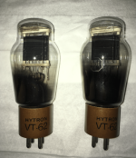
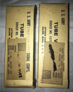
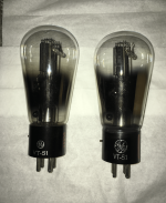
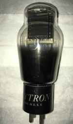
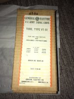
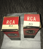
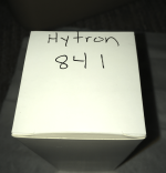
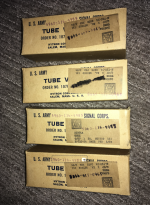
GE VT-51 GLOBE!, Hytron VT62, 801A, 841 All NOS 5-day guarantee

Multiple tubes for sale. All NOS. MINT. 5-day money back guarantee, less shipping.

Hytron 841 (1 tube): $200

Hytron 801A/VT62 (Pair or Quad) MATCHED, Sequential: $250 for 2 tubes, $500 for quad

GE VT-51 GLOBE (2 tubes, Pair) RARE: $800

Attachments

  • ss 8 7.25.59 AM.png
    ss 8 7.25.59 AM.png
    1.8 MB · Views: 130
  • ss 11 7.25.59 AM.png
    ss 11 7.25.59 AM.png
    5.2 MB · Views: 115
  • ss 12 7.25.59 AM.png
    ss 12 7.25.59 AM.png
    1.9 MB · Views: 118
  • ss 15 7.25.59 AM.png
    ss 15 7.25.59 AM.png
    1.3 MB · Views: 126
  • IMG_1156.jpeg
    IMG_1156.jpeg
    92.2 KB · Views: 97
  • ss 18 7.25.59 AM.png
    ss 18 7.25.59 AM.png
    1.6 MB · Views: 93
  • ss 16 7.25.59 AM.png
    ss 16 7.25.59 AM.png
    1.6 MB · Views: 101
  • ss 10 7.25.59 AM.png
    ss 10 7.25.59 AM.png
    5.1 MB · Views: 104

PO89ZB PCB's

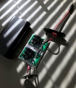
I had a small run of Mark Johnson's "inline DC filter for SMPS wall warts" PCBs made. Thread is in "Analog Line Level". I'm keeping a small stash for myself and I will distribute the rest to those that want them, no charge. Limit 2, and US only please to keep this real simple. PM me your mailing address (and quantity- one or two), and I will throw them in an envelope with a stamp. For inspiration, here is my own example showing two in series (not necessary though, a single works great).

Attachments

  • daisy chain.jpg
    daisy chain.jpg
    635.4 KB · Views: 184
  • Like
Reactions: manniraj and codyt

Sugden Connoisseur BD1 deck

Hello. I'm new here so apologies if I am posting this incorrectly or transgressing any rules.
I have a Connoisseur BD1 deck which has remained unused for over 30 years. I am having to downsize my house so am hoping to sell it to a good home.
I built this turntable in the late 1970's from a Sugden kit, into a home built timber plinth. The original tonearm was replaced with a Hadcock one (can't recall the model). I still have the original Sugden SAU2 tonearm, all the construction information and templates and alignment protractors, and miscellaneous nuts, bolts, washers and allen keys. There is an AKG P7E cartridge in amongst the items and an unknown cartridge fitted to the Hadcock arm. There is no plinth cover.
The turntable works, having been switched on after 30+ years. I'm not sure of the condition or serviceability of the cartridges, and the Hadcock arm probably needs a very careful set up. I loved this turntable at the time and used it for years until my lifestyle dictated that a less fiddly and sensitive set-up was required.
I have pictures available. I'm based in the northwest of England. Any comments or interest appreciated. Thanks.

Simple Push Pull - CFP Output transistors heating up fast

I have this simple push pull amplifier using a sziklai setup. However, the ouput transistors are heating up fast, so far no heat felt on other components. Simulation tells me that I should be getting about 700mW dissipation on Q1 and Q2 so why the heat?

Actual Measurements:

Bias diodes - Across both is ~1.4V (as expected from simulation)
Output transistor Base - ~25V (as expected from simulation)
DC output - 100mV to 200mV. Its far from simulated value.

Attachments

  • Screenshot 2023-05-19 105111.png
    Screenshot 2023-05-19 105111.png
    6.5 KB · Views: 226
  • Screenshot 2023-05-19 105050.png
    Screenshot 2023-05-19 105050.png
    13.9 KB · Views: 230
  • 2023_05_19 10_28 AML.jpg
    2023_05_19 10_28 AML.jpg
    349 KB · Views: 204
  • 2023_05_19 10_28 AM .jpg
    2023_05_19 10_28 AM .jpg
    336.3 KB · Views: 138
  • 2023_05_19 10_30 AM.jpg
    2023_05_19 10_30 AM.jpg
    272.3 KB · Views: 197

FS - Complete set for audio streamer (Pi4 2GB + IQAudio DAC Pro + 8.8" screen + 32gb card)

Here is a set of parts for you to start building a streamer based on the Raspberry Pi 4 and Volumio.

The set includes the Raspberry Pi 4 2GB, IQ Audio DAC Pro (RCA and XLR output), HannStar 8.8" screen (non-touch) and pre-installed latest Volumio 32gb card. The screen still has plastic cover on it. Working great for me for a while, I just don't have time to build a chassis for it. :-/

Asking price is $195 plus whatever shipping. I'm located in Vietnam now.

IMG-1345.jpg


IMG-1346.jpg


IMG-1344.jpg


IMG-1342.jpg


IMG-1343.jpg

Rega Elicit MK2

Hello,

I have a Rega Elicit mk2 and after some year of use it started having the problem of going silent after a hour of music play.

If I shutdown the amp and turn it back on after some time, the amp would play but again but not for long.


After hours of search on internet, I thinks it's due to the protection circuit.


For the beginning i would like to check the bias but i dont know the correct value and process for this amp.


Let me know if anyone if someone has the diagram or the adjustment procedure for this amplifier !


If you have already run to this problem with the same amp let me know how you have fixed it.


Thanks.

Quad ESL 57 one speaker quieter loss of almost 3-5db, REW measurements

Hi All

So i own a lovely pair of quad 57s which i've owned for almost 2 years. I bought them second hand where they had been worked on, new treble protection boards, EHT boards done etc basically everything was updated except the panels which were tested to be ok.

I recently moved home and these were in storage for around 3 months, i recently got them back into the house and left them connected for 24 hours, i started to notice one speaker felt louder than the other.

I swapped the speakers over (left to right, right to left) changed amplifiers and it was still the same. So i thought ok, maybe being in storage, temp changes ill leave them to charge for a few days.

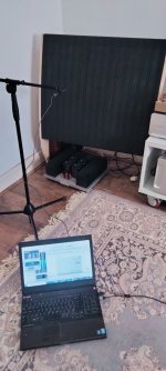
Today i took some measurements of each speaker. Left bass panel, treble panel and right bass panel. Speaker A is the good speaker, speaker B is the one i have issues with.

First thing was a pink noise test, i setup my umik mic around 5 cm away from each panel and measured the dB.

On Speaker B the treble panel was some 2.4db lower than the bass panels, where as speaker A all the panels were similar.

Speaker B was measured at 80dB white noise

With the same output volume i measured speaker A which ended up being 82db!

Speaker A

Bass panels 82db, treble panel 82dB

Speaker B

Bass panels 80db, Treble panel 77.6db


Here the weird part, i did some frequency sweeps keeping the speakers at the same volume and the panels measure similar?

Treble panels speaker A&B

treble panels.jpg


Left Bass Panels

left bass panels.jpg


Right Bass Panels

right bass panels.jpg


Now they seem to both perform well so all the panels are working, ok speaker B treble panel seems to have lost 3dB of volume and i may need to look at the panel. Overall there just seems to be a loss of efficiency and volume on speaker B?

Just need advice on what to do now and what to test?

Any advice appreciated!

Many thanks

Attachments

  • IMG20220310102953.jpg
    IMG20220310102953.jpg
    318 KB · Views: 179
  • IMG20220310103127.jpg
    IMG20220310103127.jpg
    232.1 KB · Views: 181

Quad ESL 57 – crossover/phase issue?

I purchased my rebuilt Quads some months back. Unfortunately, I feel that one of the speakers (left speaker) has a crossover/phase issue. It is about 2.5dB down compared to the other speaker. Also, I have to use them with one speaker connected electrically out out of phase in order to sound in-phase!

According to the seller they have had new OTEC bass and treble panels, 2 x RBT57 EHT boards, 2 x CLP57 clamp boards and 2 x transformer component update.

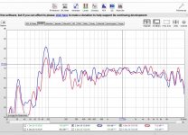
My REW measurements using the UMIK mic at listening position about 11 ft from the Quads shows the response curves when measured separately as in graph 1, Red trace left and blue trace right-hand speaker.

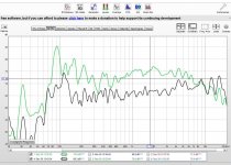
Graph 2, shows the response of the two Quads measured together. Green trace is electrically out of phase but sounds in phase. Note the increased roll-off at the treble end compared to the curves in Graph 1, indicating some cancellation I think? This makes me wonder if the crossovers are mismatched?

When both Quads are connected electrically in phase (black trace), the response is looking good apart from a slight rise at the treble end. Unfortunately, they sound very much out of phase.

When listening to pink or white noise at listening position dead centre of the two speakers, I only have to move my head slightly to the right or left and the sound becomes slightly brighter rather than the other way round, Also there is a bit of phasiness going on.

Despite my concerns, the speakers do sound very nice indeed. But being a bit of a fusspot, I do like to have things as perfect as possible!

Actually, I use the Quads with a pair subwoofers and Audyssey up to 150Hz to smooth out the bass.

I would appreciate if someone could advise me what the issue might be. (if indeed there is one!)

My listening room:
18'9” x 15' into bay window x 9' ceiling. Carpeted on suspended floor.
Currently using a Quad 303 power amp.

Attachments

  • Graph 1.jpg
    Graph 1.jpg
    119.1 KB · Views: 262
  • Graph 2.jpg
    Graph 2.jpg
    112 KB · Views: 221

2A3 versus 6B4G/6C4C

Has anyone compared 2a3 tubes to 6B4G or 6C4C tubes in the same setup?

Not so easy since they have different sockets and filament voltages.

I'd like to know which are the best sounding devices. I know EH 2a3s sound better than Sovteks, and that the Sovtek 6C4C looks identical to the 2a3 version. But I haven't heard vintage 6B4G tubes. And also the usual 6C4C tubes are Svetlana and supposed to be modelled on the old RCA 2a3, so should be a step up from the Sovteks.

Any discussion here much appreciated. Looking to get a really good pair of one or the other for a build. Is there any mileage in building with 6B4Gs or should one stick to 2a3s?

Coupling caps change for subsonic filter

I recently bought an EAR 834p clone. Sounds quite nice nice, but I am going to upgrade the coupling caps.
I have a bit of an issue with subsonics making their way to my speakers, causing some low frequency woofer movement.

Can I adjust the size of the coupling caps after either the first tube (a 0.1uf instead of a .15uf) or the 3rd tube (.47uf instead of a 1uf) to effectively create a high pass filter on subsonics? Which is the better place to do so?

https://www.vinylengine.com/turntable_forum/download/file.php?id=95993&mode=view

I tried these filters on my interconnects: https://store.acousticsounds.com/d/60042/DB_Systems-DB_Systems_Subsonic_Filter-Turntable_Accessories
They worked to filter the subsonics, but I did not care for how they colored / confised the sound, and they rolled off too much audible bass.

diy Aleph J testing?

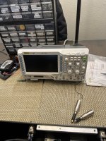
Hello to all on this forum. I would like to know if any of you would be interested in guiding me through testing my recent diy Aleph j build. I have just purchased my first scope and it really seems like a sh---t load of knobs and buttons. The amplifier I am trying to test has 400mv bias on both channels and close to 0 offset, it does play music. I would like to do a performance check on it. I have added some pics of my build and the o-scope I purchased . would appreciate any help thanks.

Attachments

  • IMG_0006.jpg
    IMG_0006.jpg
    609.2 KB · Views: 174
  • IMG_0007.jpg
    IMG_0007.jpg
    408.3 KB · Views: 156
  • IMG_0010.jpg
    IMG_0010.jpg
    386.1 KB · Views: 152
  • IMG_0011.jpg
    IMG_0011.jpg
    380.7 KB · Views: 142
  • IMG_0012.jpg
    IMG_0012.jpg
    604.1 KB · Views: 149
  • IMG_0013.jpg
    IMG_0013.jpg
    720.6 KB · Views: 161
  • Like
Reactions: ranshdow

Improve F6 further

I’ve built a F6 last year from diyaudio boards, transistors and input transformers. I find the sound warm and topend slightly rolled off. The bias is 520-30mV. I have a Schiit Aegir and this is the observation when I compare both.

my queastion is how can I take the F6 further up a notch? Keeping the same tonal balance in midrange but open up the highs a bit and a slightly tighter bottom end?

Will replacing the 1000uF caps to Mundorfs help? How about building dual mono power supplies feeding dedicated amp channel?

thanks
  • Like
Reactions: HeyBill

Once upon a time Series, Shunt and Ladder attenuator calculator for selectable (ie. ≥ 24, ≤24) steps

Years ago there were online a few resistance value calculators for stepped attenuators with user selectable number of steps with at least one going well above 60 (100?) steps if you put that in.
Does anybody happen to remember any calculators of that sort? Even if there's no longer an active link, if you do remember whose it was there's a chance it could be found in the archive.
Thanks
Projects by fanatics, for fanatics
Get answers and advice for everyone wanting to learn the art of audio.
Join the Community
507,706
Members
7,885,130
Messages

Filter

Forum Statistics

Threads
406,077
Messages
7,885,130
Members
507,706
Latest member
thatchacha10