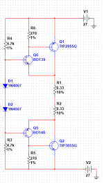
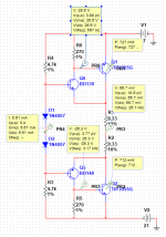
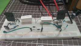
I have this simple push pull amplifier using a sziklai setup. However, the ouput transistors are heating up fast, so far no heat felt on other components. Simulation tells me that I should be getting about 700mW dissipation on Q1 and Q2 so why the heat?
Actual Measurements:
Bias diodes - Across both is ~1.4V (as expected from simulation)
Output transistor Base - ~25V (as expected from simulation)
DC output - 100mV to 200mV. Its far from simulated value.
Actual Measurements:
Bias diodes - Across both is ~1.4V (as expected from simulation)
Output transistor Base - ~25V (as expected from simulation)
DC output - 100mV to 200mV. Its far from simulated value.
Attachments
The power transistors start to conduct at 0.5v.
Measure the VBE with a meter in the diode setting.
Measure the VBE with a meter in the diode setting.
I measured about 0.66V on Q1 (2955) while about 0.56V on Q2 (3055).Measure the VBE with a meter in the diode setting.
At 700 mW you would expect 45-50 deg C case temperature with no heatsink which would feel reasonably hot. What's the bias current (calculated from voltage across R1 or R2)? You should have a Vbe multiplier instead of just 2 diodes in series if you weant to accurately set the bias current.

It's about 29-30mAWhat's the bias current (calculated from voltage across R1 or R2)?
I am going to use a Vbe multiplier in the final circuit, but If I cant get it working fine with just two diodes, how much more with a Vbe multipler
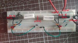
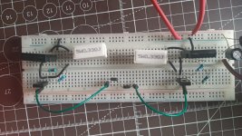
Exactly - So, where are the heatsinks? If you want to "breadboard" power amplifiers, you still have to stabilise their bias current dissipation or perhaps there's even some low level oscillation which causes the excess heat. It's difficult to predict what might occur, so you would need a real oscilloscope to see what was really going on. Multisim models are probably not accurate enough to show instability and other free sim. packages are probably also weak in that area.
Last edited:
A power transistor without a heatsink is going to heat up fast, that's why we use heatsinks with them. 700mW will get any transistor hot in free air. Most packages have thermal resistances whe unmounted in the order of 30 to 100 C/W, mounting a power device on a large heatsink brings this down to maybe a couple of C/W.
Thermal resistance to free air is normally not specified for a power device as you would never use them unmounted...
Thermal resistance to free air is normally not specified for a power device as you would never use them unmounted...
So just heatsink it is, thanks to you all.
I hope this place is not like stack.
Is the use of CFP a taboo or is creating a thread about it a taboo?Not another CFP thread. They should be banned.
I hope this place is not like stack.
What's that - - a search gives "Fluorinated polymeric surfactant with a pluronic-like substrate"
By the way, I have a 0.47 ohm resistor in the base of the outputs. Try that; apart from the heatsink of course.
By the way, I have a 0.47 ohm resistor in the base of the outputs. Try that; apart from the heatsink of course.
1. Any CFP must be loaded with a Zobel network for stability/oscillation.
2. The base resistors on OPs should be 100 Ohms or less, especially with older ~1MHz parts.
3. The input to the drivers should be low-Z at high frequencies. Typically, that comes from the VAS compensation cap.
4. The breadboard and the lengthy wiring is an invitation to all manner of unpredictable coupling.
For max. homogenity:
Q6 - TIP3055
Q5 - TIP2955
But TO-3P-casings sound very relaxed, but also without high color resolution, and without contour and colors to get together, a bit flat, noisy, hung up.
Most TO-247 will sound better. Even better TO-220. They should also suffice for most power desires.
Q6 - TIP3055
Q5 - TIP2955
But TO-3P-casings sound very relaxed, but also without high color resolution, and without contour and colors to get together, a bit flat, noisy, hung up.
Most TO-247 will sound better. Even better TO-220. They should also suffice for most power desires.
But TO-3P-casings sound very relaxed, but also without high color resolution, and without contour and colors to get together, a bit flat, noisy, hung up.
Most TO-247 will sound better. Even better TO-220. They should also suffice for most power desires.
High end snake oil b u l l s h i t theory.
Most TO-247 will sound better. Even better TO-220. They should also suffice for most power desires.
High end snake oil b u l l s h i t theory.
Your circuit doesn't show any load on the output. That is, a resistor to ground or a Zobel. The circuit might be oscillating.I have this simple push pull amplifier using a sziklai setup. However, the ouput transistors are heating up fast, so far no heat felt on other components. Simulation tells me that I should be getting about 700mW dissipation on Q1 and Q2 so why the heat?
You should also have PSU decoupling caps on the breadboard going to ground. Make a star ground point on your breadboard. And the input should have some resistance to ground.
In a simulator having things floating will not be a problem but reality is different
Yes, your only problem at the moment is the lack of a heat sink.So just heatsink it is, thanks to you all.
Is the use of CFP a taboo or is creating a thread about it a taboo?
I hope this place is not like stack.
But when amplifiers are built around them they often have problems that are not easy to solve, at least not without significant compromise. Resulting in a lot of off-the-reservation discussion, pseudo-science, and snake-oil sales. The kind of thing that gets moderators upset and threads closed. It’s already started here.
There is nothing inherently wrong with a CFP, and I’ll use them where appropriate - WHEN the compromises you end up making to ensure stability can be accepted. Not every amplifier needs 200+ watts, 10 ppm distortion, 100V/us slew rate, or needs to operate into a pure capacitor. If those are your goals, CFP will be more trouble than it needs to be.
1. Any CFP must be loaded with a Zobel network for stability/oscillation.
aye, I indeed have the output floating, as for the oscillation, Indeed I am poor I cant afford a scope, so what I did is measure the output with the AC voltmeter, there's a fluctuating reading, even in DC.Your circuit doesn't show any load on the output. That is, a resistor to ground or a Zobel. The circuit might be oscillating.
I got them to the value such that the quiescent current on the output is low. This is a mistake, this is where a Vbe multiplier must be used.2. The base resistors on OPs should be 100 Ohms or less, especially with older ~1MHz parts.
I apologize, I can't understand this, I am guessing this is the miller cap.3. The input to the drivers should be low-Z at high frequencies. Typically, that comes from the VAS compensation cap.
Right, I made a mini antenna4. The breadboard and the lengthy wiring is an invitation to all manner of unpredictable coupling.
I got 100uF on both rails to ground, my PSU also has decoupling caps before that, just not shown in the pic. As for the input, I indeed had it floating, I'll just ground it through resistor instead of keeping it floating if no input is intended.You should also have PSU decoupling caps on the breadboard going to ground. Make a star ground point on your breadboard. And the input should have some resistance to ground.
Thanks for your inputs, I got something from them.
- Home
- Amplifiers
- Solid State
- Simple Push Pull - CFP Output transistors heating up fast