Hello,
I have a Rega Elicit mk2 and after some year of use it started having the problem of going silent after a hour of music play.
If I shutdown the amp and turn it back on after some time, the amp would play but again but not for long.
After hours of search on internet, I thinks it's due to the protection circuit.
For the beginning i would like to check the bias but i dont know the correct value and process for this amp.
Let me know if anyone if someone has the diagram or the adjustment procedure for this amplifier !
If you have already run to this problem with the same amp let me know how you have fixed it.
Thanks.
There's a series relay in line with the speaker, so even with the relay contacts open, you can check
the amp output before the relay contacts to see whether the output DC voltage is excessive.
Only if the amp seems ok should you attempt to troubleshoot the protection circuit.
If so, the odds are the two low voltage back-to-back electrolytics, rated at 100uF 10V.
Replace these with a single 100uF 50V bipolar electrolytic.
https://www.mouser.com/ProductDetail/Nichicon/UES1H470MPM
Attachments
Last edited:
Thank you for your reply!
Agree with this idea, what I can do during a cut is to inject a sine of 300mV in the aux input and look at the shape of the signal and the presence or not of a DC component on TP5 and TP2.
To cause the breakdown, I think to load it with two 8ohms dummy load.
Is that what you meant?
Agree with this idea, what I can do during a cut is to inject a sine of 300mV in the aux input and look at the shape of the signal and the presence or not of a DC component on TP5 and TP2.
To cause the breakdown, I think to load it with two 8ohms dummy load.
Is that what you meant?
Last edited:
I will wait the weekends to open it and do these checks.
I'll post some pics here !
Otherwise, is there a procedure to control and adjust bias on this amp?
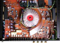
In this picture you can see a trim for each side of the amp. I think it's for the bias adjustment.
I'll post some pics here !
Otherwise, is there a procedure to control and adjust bias on this amp?
In this picture you can see a trim for each side of the amp. I think it's for the bias adjustment.
Attachments
The emitter resistors appear to be 0.47 Ohms each. No bias info is given.
I would not adjust the bias pot unless you get good information about it.
Often in many amplifiers the bias is adjusted for around 26mV across each emitter resistor,
which would be .026V / 0.47 R = 55mA bias current.
Others adjust by the heat sink temperature after about 1 hour of idle, around 50F.
But maybe someone knows what Rega specifies for this particular amplifier.
Last edited:
Thank you for that answer!
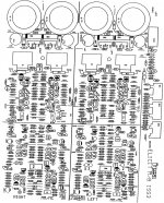
one thing scares me a little, I have the impression that the diagrams are not those of my amp because the photo of the installation corresponds to a rega elicit MK1.
maybe the diagrams of the amplification part are still the right ones?
one thing scares me a little, I have the impression that the diagrams are not those of my amp because the photo of the installation corresponds to a rega elicit MK1.
maybe the diagrams of the amplification part are still the right ones?
Attachments
Good morning,
Some news, I haven't done any measurements yet because my probes are too big, I'm waiting for finer news!
On each power amplifier there is a "DC TEST" jumper.
It allows to insert or not 2 capacitor in the circuit.
Does anyone know what this kind of jumper is for?
Other informations, the emitter resistors of my amp are 0.22 Ohms each and the is 2 IQ tests point per side amp.
Last edited:
Hello,
I made progress on my troubleshooting!
First of all, you need to know that when the sound cuts out (after 2h30 at -20dB: 13 leds / 20) the amplifier was not hot (31.7°C).
The output relays were still on! I therefore deduce that the self-protection has not been activated!
Other observations, by lowering the volume to 4 leds / 20, it started to work normally again!
After 5 minutes of sleep we go good and work well.
The DC offset between each output terminal, it is very stable.
Cold :
left channel: -0.1mV
right channel: 1.2mV
Hot
left channel: 1.3mV
right channel: 2.1mV
I noticed that when switching on the LEDs of the buttons and the volumes light up randomly!
Could the problem come from the management card?
Maybe a bad solder ?
Thank you in advance for your advice
Hello,
I made progress on troubleshooting.
it is located on the preamp part.
When the amp fails, I no longer have a signal at the output of the XWM8816G (pin for 15 R and 2 for L ).
the R and L input signals are still present. the +5V supply too.
The chip have a little brown aspect.
If someone know where i can find a original XWM8816G for a good price ...
Attachments
Last edited:
Hello, I have some news.
I redid the welds and now the output of the xwm8816g seems correct to me.
however I lost the left channel in the preamp!!!
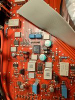
I probed and at the output of the preamplifier I have no amplification at the output of TR4 and TR5 (see the red dots). I find the input signal at the output.
the +15v and -15v is ok.
Do you have an idea to help me move forward?
thank you very much in advance.
I redid the welds and now the output of the xwm8816g seems correct to me.
however I lost the left channel in the preamp!!!
I probed and at the output of the preamplifier I have no amplification at the output of TR4 and TR5 (see the red dots). I find the input signal at the output.
the +15v and -15v is ok.
Do you have an idea to help me move forward?
thank you very much in advance.
Attachments
- Home
- Amplifiers
- Solid State
- Rega Elicit MK2