Sorry, but I don't know what this refers to. Can you educate me?Perhaps a PR1 setting will correct this?
I don't know what's responsible for the gain difference, but would imagine it's easier to resolve than a failed WM8816.
I ordered a new XWM8816G.
I'll let you know when I receive it!
with regard to PR1, it is the variable resistor "DC BAL PRE LEFT"
I'll let you know when I receive it!
with regard to PR1, it is the variable resistor "DC BAL PRE LEFT"
Thanks. I don't think it will have any effect upon gain. I believe you'll find that you if you tweak PR1, U4 pin 1 will move in concert. I think it's intended to permit nulling of U4 to 0V, i.e. middle of its control range.
I checked and you are absolutely right!
I will proceed to replace the Xwm8816g and then I will check for the gain.
what would be the correct procedure for nulling U4 to 0v ?
No input and read value on ?
I will proceed to replace the Xwm8816g and then I will check for the gain.
what would be the correct procedure for nulling U4 to 0v ?
No input and read value on ?
Correct! Null U4 pin 1 to 0V. This will center the adjustment range available to U4.
Servo nulling is interesting. The intent is to drive the amp output (red dot at R84, R85) to 0VDC, but the amp doesn't provide a trim for offset error in U4A. The red dot node will servo to the offset error of U4A.
The motivation for all this is to ensure that the discrete amp has low offset error so that when the WM8816 manipulates gain there is minimal shifting of the output bias at the red dot.
Good morning,
Thank you for this detailed information! I understand better the role of PR1 !
I will make the adjustment with the new XWM8816G
Thank you for this detailed information! I understand better the role of PR1 !
I will make the adjustment with the new XWM8816G
The right channel does respond to varying the volume control? That would of course confirm that control signals are reaching the volume IC.
To add certainty to diagnosis of failed U4, would you confirm that line level test signals arrive successfully at U6 pin 4? With the JP2 and JP3 jumpers still in the 2-3 positions, you might probe the pin 1 post on each of those two sites and for look for any test signal remnants. Also. ohmmeter continuity checks of each pin1 back to its respective U6 lead would be good precautions.
Good luck!
All was good on the right chanel.
I started by doing these checks before opening the post.
The signal arrives well on the input of the component.
it is well powered and well grounded.
The tracks are ok !
Before the failure, I had a problem, I had to turn up the volume to 13 led / 20 to have a high enough sound.
This corresponds roughly to -28dB. It seemed suspicious to me.
Well, lots of reasons to suspect U6 and you've done all the due diligence I can think of. I hope the replacement IC does the trick!
Hello everyone,
I replaced the XWM8816G. the amplitude works perfectly!
the outputs are symmetrical (I do not find the pb of gain).
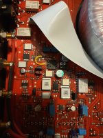
unfortunately a pad was damaged...
so I made a bridge.
maybe the iron was too hot (375°c) or the tip too thick... it's sad.
I replaced the XWM8816G. the amplitude works perfectly!
the outputs are symmetrical (I do not find the pb of gain).
unfortunately a pad was damaged...
so I made a bridge.
maybe the iron was too hot (375°c) or the tip too thick... it's sad.
Attachments
Hello,
I'm coming back here after a few months. The amplifier works but I think it has a problem.
Maybe I'm wrong, but I think the preamplifier gain setting is no longer good. The power is available only very late.
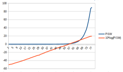
There is 80 positions on the volume encoder. Each position allows an increment of 1dB.
With an 8 ohm load, the first output watt is obtained at 57 stops of the volume encoder
I plotted the curve of the output power as a function of the position of the encoder.

I'm coming back here after a few months. The amplifier works but I think it has a problem.
Maybe I'm wrong, but I think the preamplifier gain setting is no longer good. The power is available only very late.
There is 80 positions on the volume encoder. Each position allows an increment of 1dB.
With an 8 ohm load, the first output watt is obtained at 57 stops of the volume encoder
I plotted the curve of the output power as a function of the position of the encoder.
The detail of my calculation is as follows :
position 57 -> output = 8V peak to peak -> Ueff = 2.82V -> P = 1W -> dB = 10*log(1) = 0dB
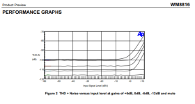
In the datasheet of the XWM8816G i I've found this.
position 57 -> output = 8V peak to peak -> Ueff = 2.82V -> P = 1W -> dB = 10*log(1) = 0dB
In the datasheet of the XWM8816G i I've found this.
Attachments
Last edited:
- Home
- Amplifiers
- Solid State
- Rega Elicit MK2